CHAPTER FIVE
Handling Black Boxes: Planning Around a Module That Is Not There Yet
By the end of this chapter you will be able to look at a netlist that is missing modules and tell, from attributes alone, which kind of hole each one is; to turn those holes into black boxes that the floorplanner, the shaper and the budgeter all treat as real; to give a black box the one number it cannot do without and the one it must never be given by mistake; to build it a timing model so that paths crossing it stop being unconstrained; to say what its power intent has to declare and why a block's would not do; and to recognise the several ways this can go quietly wrong, none of which produces an error message.
Why this chapter matters in a real project
Design planning almost never starts with a complete netlist. Somebody is late. A licensed block has not arrived, an RTL team is a sprint behind, a derivative design is reusing a module that is still being rewritten, or a wrapper exists as a name in a spreadsheet and nothing else. The schedule, meanwhile, does not move: the floorplan is needed by the same date whether or not every module is in the file you were given.
The choice at that moment is not between planning and waiting. It is between planning with numbers you chose deliberately and planning with numbers the tool made up on your behalf. A black box is the mechanism for the first of those. It lets you say, in a form every downstream command respects, this module will be roughly this big, it will take roughly this long, and it will be powered from here — and then get on with shaping, power planning, pin assignment and budgeting as though the module existed.
What makes this chapter worth reading slowly is the failure mode. Every other chapter in this book so far has had a tool that pushes back: an illegal boundary is rejected, a missing library is reported, a constraint file that does not parse stops the script. A black box with the wrong area is accepted without comment. It shapes, it places, it routes, it budgets, and every report about it looks healthy — because every report is computed from the number you typed. The netlist that would have contradicted you does not exist. You find out eight or ten weeks later, when the real module arrives twenty per cent bigger than the hole reserved for it, and the entire floorplan has to move.
So the discipline this chapter teaches is narrow and specific: know exactly where each number came from, write it down, and check it the day the netlist lands.
Prerequisites
Chapter 1: the area estimate, standard-cell area, macro area, and the internal utilisation that turns placeable area into a block boundary. Chapter 2: units, and the habit of reading a value back out of the tool instead of trusting what you typed. Chapter 3: modes, corners and scenarios; split_constraints and the files it writes; load_block_constraints; and multiply-instantiated blocks. Chapter 4: the die, the core and the core offset, and how each block's boundary area lands in the same core arithmetic.
How to read the numbers and the notation in this chapter
This chapter is arithmetic-heavy, and none of the arithmetic is hard — but it is easy to be tripped up by notation rather than by the engineering. So before anything else, here is every symbol and unit the chapter uses, spelled out. Skip this if it is already familiar; come back to it the moment a number looks odd.
| You will see | Read it as | What you need to know |
|---|---|---|
| mm² | square millimetres | An area. The whole chip and the blocks on it are measured in these. Nimbus-8's core has an area of 10.24 mm². |
| µm² | square microns, sometimes written square micrometres | Also an area, just a much smaller one. This is the unit the tool itself works in, so it is the unit you type. 1 mm² = 1,000,000 µm² — six zeros, because a millimetre is a thousand microns and area squares that. So 1.716667 mm² is 1,716,667 µm². |
| µm | microns, or micrometres | A length, one thousandth of a millimetre. Row heights and track pitches are quoted in these. |
| ps | picoseconds | A time, one thousandth of a nanosecond. Every timing number in this chapter is in picoseconds, because that is the time unit Nimbus-8's session is set to. 1 ns = 1,000 ps. |
| × ÷ − | multiply, divide, subtract | Ordinary arithmetic, printed with the proper signs so that a multiplication is never mistaken for the letter x and a subtraction is never mistaken for a hyphen in an option name. |
| 1,716,667 | one million, seven hundred and sixteen thousand, six hundred and sixty-seven | Commas group the digits in threes so a long number can be read at a glance. They are punctuation only. When you type this number into a command you type it with no commas at all: 1716667. |
| a square 3.20 mm on each side | a square whose sides are each 3.20 mm long | This describes a shape and a length, not an area. Its area is a separate number: 3.20 × 3.20 = 10.24 mm². The chapter always gives both, because the two are easy to confuse and only one of them is what a command wants. |
| Section 5.4.4 | section 5.4.4 of this chapter | A cross-reference. The first digit is the chapter, so anything beginning “5.” is somewhere in these pages. Follow it if you want the detail now; ignore it if you would rather keep reading. |
create_blackbox | a command, exactly as typed | Anything in this typewriter face is something you type at the tool, or a name the tool uses. It is reproduced character for character, so spelling and underscores matter. |
| -library | an option belonging to a command | The leading hyphen marks it as an option, not a subtraction. Options are typed after the command name, in any order, each followed by its value where it takes one. |
The one to hold on to is the second row. Areas are estimated in square millimetres, because that is the scale a human thinks in, and they are typed in square microns, because that is the scale the tool works in. Every area in this chapter is therefore printed twice, once in each unit, so that you never have to do the conversion in your head while also thinking about the engineering. When you meet a number on a real project with no unit attached to it, that is the first question to ask, not the last.
Learning objectives
- Define a black box by the three conditions that produce one, and state the single restriction on which hierarchies may become one.
- Classify a candidate module as missing, empty, partial, feedthrough or tie-off using the documented attributes, and say which attribute settles each case.
- Create a black box reference with
create_blackboxand predict all three of its side effects, including the one that touches modules you did not name. - Choose between
target_boundary_areaandtarget_utilization, compute the value each needs from an area estimate, and quantify the error the wrong choice produces. - Build a black box timing model with the nine commands that describe one, in an order that works, and commit it into the abstract view.
- Compute how much of a clock period a committed model leaves for the top-level route, and name the application option that decides whether the budgeter may change it.
- Explain why a black box's UPF differs from an ordinary block's, and extract one from an existing design rather than writing it by hand.
- Diagnose at least six black box failure modes, including one whose symptom points at the wrong block entirely.
5.1 The beginner's mental model
Start with a lot that has no building on it
Imagine you are drawing up a site plan for four lots. Three of them have buildings with finished architectural drawings: you know their footprints exactly, so you can place them, run the access roads between them, and work out how much of the site is left. The fourth lot is going to hold a building nobody has designed yet.
You do not stop. You reserve the fourth lot at the area the brief calls for, you note where its doors will be — because the brief fixed those, even though the building did not — and you carry on with the roads, the drains and the electricity supply. When the drawings finally arrive, one of two things happens. Either the building fits the lot you reserved, and nothing changes; or it does not, and you find out that the roads, the drains and the supply were all laid out around the wrong number.
That is a black box, almost exactly, and the whole vocabulary transfers. The reserved area of the lot becomes an attribute called target_boundary_area. How densely the lot may be built on becomes target_utilization. The doors in known places become the module's port interface, which exists in the instantiation even when the module does not. How long a delivery takes to cross the lot becomes a command called create_blackbox_delay, and how long a lorry must wait at the door before it may be unloaded becomes create_blackbox_constraint. Which mains feeds the lot becomes the receiver supply in the power intent. Figure 5.2 lays all seven of those pairs out side by side; do not try to memorise them from this paragraph.
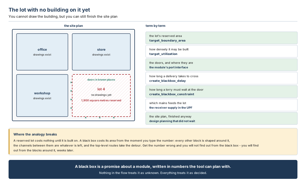
A reserved lot is a placeholder: it costs nothing until somebody builds on it, and if the brief changes you re-reserve it. A black box is not a placeholder. From the moment the number is typed, it is spent. Every other block is shaped around that area, the channels between blocks are whatever the area leaves over, the power mesh is planned across it, pins are assigned on its edges, and the top-level nets that have to get past it take the route its boundary allows.
The second difference is worse. On a site plan, an empty lot looks empty — anyone glancing at the drawing can see that the fourth building is missing. In the tool, a black box looks finished. It has a boundary, a utilisation, a shape, an abstract, pins and a timing model, and every report you can run about it returns clean numbers. The one thing that would have contradicted you is the netlist, and the netlist is precisely what does not exist.
Now the engineering model
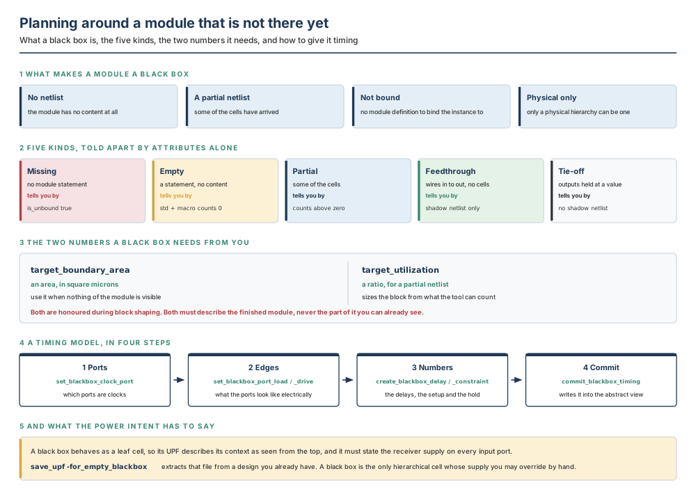
A black box is a module that has no netlist, has only a partial netlist, or is not bound to a higher-level module. That definition has three clauses and they are genuinely different situations, which is why Section 5.2.1 spends a page separating them.
Two facts about black boxes bound the whole chapter. The first is a restriction: only physical hierarchies can be black boxes. A logical hierarchy cell must become a physical block before it can be one, and create_blackbox does that conversion for you rather than complaining. The second is the reason the mechanism exists at all: black boxes are supported for both physical and timing purposes, and at all stages of design planning. This is not a stub that lets a script get past a missing file. It is a first-class object that the following operations all handle:
Read that list as a promise and as a warning. The promise is that you lose almost nothing by planning around a missing module. The warning is that all ten of those operations will use your area and your delays without ever being in a position to question them.
Notice what the list does not say. It does not say optimisation, and it does not say routing. A black box is a design-planning object. It exists so that the plan can be made, the blocks can be handed out and the budgets can be written. Nobody implements a black box; the team who owns the real module implements that, against the budget your black box produced. This is why an area error propagates so far before anybody notices: the plan is the deliverable, and the plan looks fine.
The four-step flow, before any detail
The whole chapter is four steps, and they are worth holding in mind while the detail arrives:
- Identify potential black boxes, by reading attributes on cells with
get_attribute. - Create black box references, with
create_blackbox. - Create black box timing models, with the
create_blackbox_*andset_blackbox_*commands. - Commit the timing models, with
commit_blackbox_timing.
Steps 1 and 2 are physical: they give the module a size and a shape so the floorplan can be finished. Steps 3 and 4 are temporal: they give it delays so the timing can be closed. The two halves are independent — a black box with an area and no timing model is perfectly legal, and quite common in the first week — but the second half is the one people skip, and Section 5.4.4 shows exactly what skipping it costs.
Do not confuse these
| This | Not this | How to tell them apart in one question |
|---|---|---|
| A missing module | An empty module | Is there a module statement in the Verilog? A missing module has none and reports is_unbound true; an empty module has the statement and no content, and reports is_unbound false. Both have zero cells, so the counts alone will not tell you. |
| An empty module | A partial module | Are the hierarchy cell counts zero? Empty means nothing to place; partial means an incomplete set of cells, which the tool can and will place. |
| A feedthrough module | A tie-off module | Does hierarchy_has_shadow_netlist_only return true? A feedthrough carries nets from input ports to output ports and so has a shadow netlist and nothing else; a tie-off holds its outputs at a logical value and has no shadow netlist. |
| A black box | A hard macro | Is there a library model for it? A hard macro arrives with its own timing, physical and power models from the library. A black box has whatever you gave it and nothing more, and it is a hierarchical cell rather than a leaf cell — although its power intent is written as though it were one. |
target_boundary_area | target_utilization | Do you want to state a size, or a density? The first is an area. The second is a ratio that the tool multiplies by content it can count — so on a module with no content it has nothing to work with. |
| The black box's boundary area | The block's placeable area | Which one includes the space between the cells? Placeable area is what the cells and macros occupy; boundary area is that divided by the internal utilisation. Chapter 1 made this distinction; a black box is where confusing them costs the most. |
create_blackbox | commit_block | Is there content to commit? commit_block turns a logical hierarchy into a physical block with its own netlist. create_blackbox produces a design that is marked black_box and has no content — although on a logical hierarchy cell it performs the commit as part of its work. |
| The design view | The abstract view | Where does the timing model live before and after committing? You build the model into the design view; commit_blackbox_timing writes it into the abstract view, and until it does, nothing at the top level can see it. |
| A black box's UPF | A block's UPF | Whose point of view is it written from? A block's UPF describes the block's own internals. A black box's UPF describes the black box's context, in terms of the top level, because the black box acts as a leaf cell — and it must also give the receiver supply for the input ports. |
5.2 The concepts, from first principles
5.2.1 Identifying candidates: the one attribute and the ten
Start with the easy case. If a module has already been made a black box, you can find it by retrieving cells whose black_box attribute is set to true. That is the question “what is already a black box?”, and it is the question you will ask most often once a project is under way.
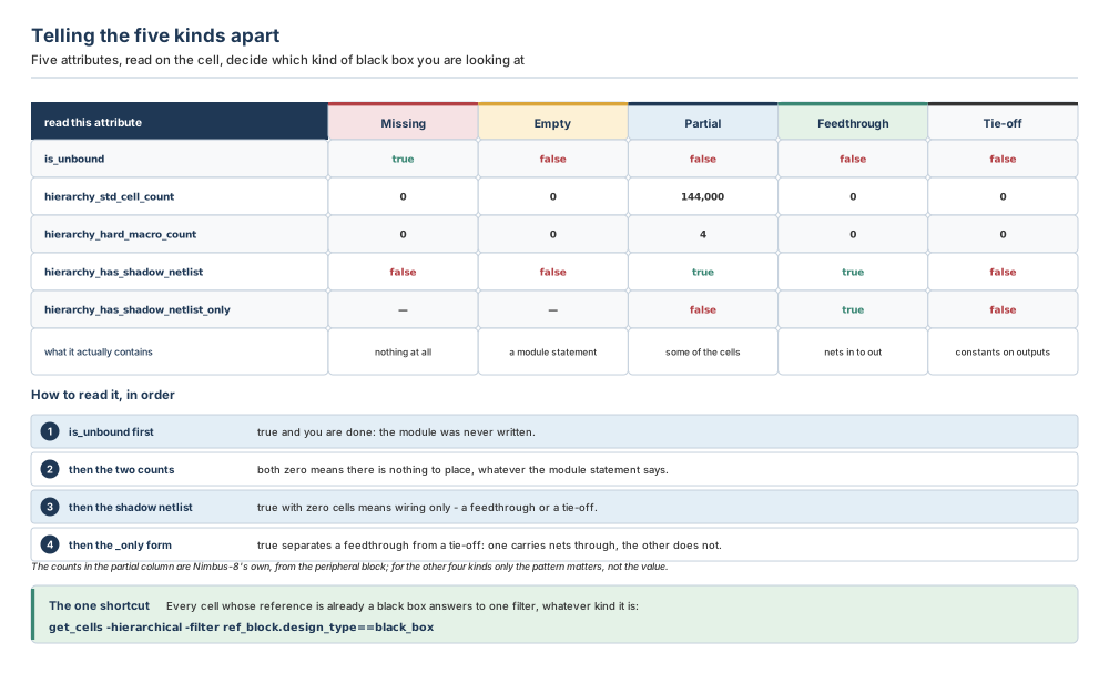
The harder and more interesting question is the one you ask on the first day: which of the modules in this netlist ought to become black boxes, and what kind of hole is each one? Black boxes classify into five kinds — missing or unbound, empty, partial, feedthrough, and tie-off — and the classification is made by reading attributes on the block. Ten attributes are documented for the purpose. Five of them do almost all the work; the other five matter when a module contains something unusual.
| Attribute | What it answers | When you need it |
|---|---|---|
is_unbound | Was there a module definition to bind to? | Always first. True settles the case immediately: the module was never written. |
hierarchy_std_cell_count | How many standard cells are in there? | Always. Zero with a module statement means empty; above zero means partial. |
hierarchy_hard_macro_count | How many hard macros are in there? | Always. Memories often arrive in the netlist before the logic around them does, so this can be non-zero while the cell count is small. |
hierarchy_has_shadow_netlist | Is there connectivity, even without cells? | When both counts are zero. True means wiring exists: a feedthrough or a partial module whose cells have not landed. |
hierarchy_has_shadow_netlist_only | Is connectivity all there is? | To separate a feedthrough from a tie-off, and to confirm a partial module has real content rather than only wires. |
has_timing_model | Does the block already carry timing? | Before you build a model, so you do not build a second one; and afterwards, to confirm the commit landed. |
hierarchy_pad_cell_count | Are there pad cells inside? | On anything near the periphery. A module holding pad cells is not the kind of hole you fill with an area estimate. |
hierarchy_physical_only_cell_count | Are there physical-only cells inside? | When a count looks wrong. Physical-only cells occupy area without being in the logical netlist, so they can make an “empty” module non-empty in the floorplan. |
hierarchy_switch_cell_count | Are there power switch cells inside? | On any multivoltage design. A module with switch cells has power intent attached to it already, and that changes what Section 5.4.5 asks of you. |
target_boundary_area | What area has been reserved for it? | To read back the number you set, and to audit numbers somebody else set. This is the attribute you will check most often in a review. |
The commands are the ordinary ones. There is no special query for this:
icc2_shell> get_attribute -objects $cells -name is_unbound
true
icc2_shell> get_attribute -objects $cells -name hierarchy_std_cell_count
0
icc2_shell> get_attribute -objects $cells -name hierarchy_has_shadow_netlist
false
That is a missing module: unbound, no cells, no connectivity. Change the first answer to false and leave the other two, and you have an empty module — a module statement with nothing inside it. Both are holes; only one of them was ever written down.
Because the five kinds are not a property the tool stores; they are a reading you make of properties it does store. A module is not tagged “feedthrough” anywhere. It simply happens to have zero cells, a shadow netlist, and a shadow netlist only — and from those three facts you conclude that it is wiring and nothing else.
This is worth internalising, because it tells you what to do when a module does not match any of the five patterns cleanly. There is no rule being broken. You are looking at a module whose attributes describe something the five names were not invented for, and the right response is to read the remaining five attributes in Table 5.3 and work out what is actually inside it.
5.2.2 The five patterns, one at a time
The distinguishing signatures are worth learning as patterns rather than as facts to be looked up, because you will read them off a report far more often than you will type them.
Missing modules have no module definition — no module statement in the Verilog netlist — and report is_unbound true, a standard-cell count of zero, and no shadow netlist. This is the cleanest case and the most common one at the start of a project: the file simply does not contain the module the top level instantiates.
Empty modules have a module definition but no content. They report is_unbound false, standard-cell and hard-macro counts of zero, and no shadow netlist. Somebody wrote the interface and stopped, which is exactly what a well-organised RTL team does when a block is scheduled for next month.
Partial modules contain an incomplete set of cells. Their hierarchy counts are above zero — you might see a hard-macro count of a few and a standard-cell count in the hundreds or hundreds of thousands — with a shadow netlist present, hierarchy_has_shadow_netlist_only false, and the pad, physical-only and switch cell counts all zero on an ordinary module. This is the interesting case, and Section 5.2.6 is largely about it.
Feedthrough modules contain net connections between input and output ports and no cells at all. Zero standard cells, zero hard macros, a shadow netlist present, and hierarchy_has_shadow_netlist_only true. Wrapper modules that exist only to carry signals across a hierarchy boundary look exactly like this, and they are common in real netlists.
Tie-off modules have only output ports, tied to a logical value. Zero standard cells, zero hard macros, and no shadow netlist at all — neither the plain form nor the _only form. A module that reports constants is not carrying anything through, so there is nothing for a shadow netlist to hold.
“Feedthrough and tie-off modules are black boxes, so I should run create_blackbox on them too.”
They are listed among the kinds of black box, and the attributes are given so you can identify them. What follows from that is a judgement, not a rule, and the judgement usually goes the other way. A feedthrough or a tie-off module has no cells and therefore no area to reserve; making it a physical black box gives it a boundary, a shape and a place in the core arithmetic that it does not need, and every other block gets shaped around a hole with nothing in it.
The reason the classification is worth knowing is diagnostic. When a module turns up with zero cells and you are about to reserve two hundred thousand square microns for it, the shadow-netlist attributes are what tell you that it is a wrapper rather than a late block — and that the right answer is to leave it alone, not to reserve anything.
is_unbound, then the two counts, then the shadow netlist, then its _only form. Two of the five kinds — feedthrough and tie-off — are things you identify in order to not reserve area for them.5.2.3 Nimbus-8, six weeks earlier
Everything in this chapter happens on the design this book has been carrying, at a moment earlier than any previous chapter. The netlist Chapter 3 split and Chapter 4 built a floorplan from was not the first netlist. Six weeks before it, at revision A, two of Nimbus-8's five modules were not there to be read.
The image-signal processor, u_isp, was missing outright: the top level instantiated a module called ISP and the netlist contained no such module. The SoC peripheral block, u_soc_periph, was partial: its module statement was there, its four memories were there, and about forty per cent of its standard cells were there. The CPU cluster, the two NPU cores and the DDR PHY were all complete.
And the floorplan of Chapter 4 was built anyway — the same die, the same core, the same offset, the same rows and the same tracks. Figure 5.4 shows how.
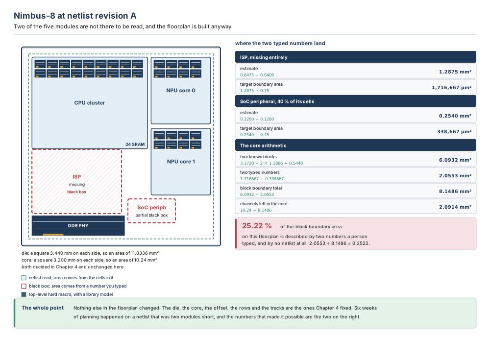
That last number deserves a moment. The two black boxes together account for 2.0553 mm² of boundary area, against 8.1486 mm² for all six blocks and macros put together, so 25.22 per cent of the block area on the Chapter 4 floorplan was, at revision A, a pair of numbers somebody chose. As a fraction of the whole core it is 20.07 per cent. Neither figure is unusual. On a derivative design or a first-of-family SoC it is routinely higher.
5.2.4 What create_blackbox actually does
Once you have decided which modules to treat as black boxes, create_blackbox creates the black box physical hierarchy for the cell and updates the cell's reference. Both halves of that sentence matter, and the second half has a reach that surprises people.
When the cell has an unresolved reference, the command creates a new, empty design with the same port interface as the unresolved reference. That is the crucial mechanism and it is worth being explicit about: the ports come from the instantiation, not from the module. A Verilog instantiation names every port it connects, so even when the module body is entirely absent the interface is fully known — which is why a black box can have a meaningful timing model and a meaningful pin assignment. The doors were in the brief.
When the cell is a logical hierarchy cell instead, the command converts it into a physical block and creates a new design holding the content of the original cell's logical hierarchy. Either way, the design that comes out is a black-box-typed design.
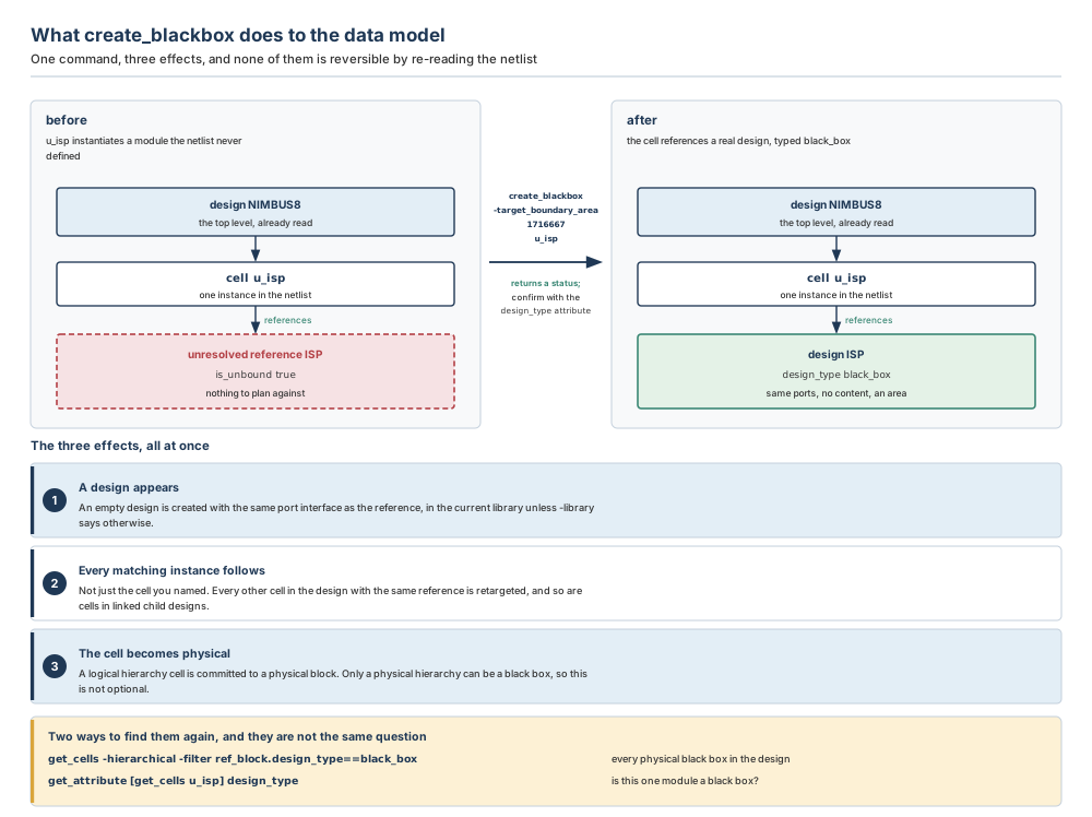
Effect two, spelled out because it matters: the reference of the cell you named and of all other cells with the same reference is changed to the new design. So are any other cells in designs linked to this design as child designs, and any designs linked with the same unresolved reference. One command, and every instance of that module in the whole linked hierarchy now points at the black box.
This is almost always what you want — a module is either late or it is not, and it is late in every instance of itself — but it means the command is not local. If you were expecting to convert one of two instances and leave the other alone, that is not what black boxes do, and Section 5.2.8 explains why the answer is not to try.
Nothing, by itself. Re-reading the netlist does not undo a black box: the reference has been changed to point at the new black-box design, and the cell will keep pointing there. Converting the black box back into a real block is a deliberate act, and on a real project it is a scheduled one — you read the new netlist, re-commit the block, re-create its abstract, and then compare its true area against the number you had reserved. Section 5.6 makes that comparison a numbered step, because it is the step that closes the loop this chapter opens.
The useful consequence is that timing is available immediately when a black box is replaced by feedthroughs or by real content: black box timing information lives in the design view, and when an abstract is created from a black box the marked cells, nets and connections are created on the fly inside the abstract. Newly created feedthroughs can therefore be timed at once, without the models having to be rebuilt.
5.2.5 Finding them again
Two questions, two commands, and they are genuinely different. To find every black box in the design, or to check whether a specific module is one, examine the design_type attribute of the module:
icc2_shell> get_cells -hierarchical -filter ref_block.design_type==black_box
{u_isp u_soc_periph}

icc2_shell> get_attribute [get_cells u_isp] design_type
black_box
The filter expression design_type==black_box is the one to remember for searching, because it works whatever kind of hole the module started as. Two related attributes exist for cases the filter does not cover: is_empty queries empty hierarchies, in the same way is_unbound queries unbound instances; and is_logical_black_box is the attribute for macro-style black boxes, which the next paragraph explains.
create_blackbox -type takes physical or macro, and the default is physical. A physical black box is a physical block and follows the physical-partition design planning flow — this is the one this chapter is about, and the one every other chapter in this book assumes. A logical or macro type black box is created for unbound instances and empty hierarchies, and after creation it is treated as any other macro in the design and is placed by the macro placer. That is a different and simpler life: no shaping, no pin assignment, no budgeting, just a rectangle the macro placer puts somewhere sensible.
Choose -type macro when the missing module is genuinely going to behave like a macro — a small hard block, an analogue island, an IP wrapper you will never open — and you want the macro placer to deal with it. Choose the default physical when the module is a real design block that will be shaped, budgeted and handed to a team. Nimbus-8's ISP is the second kind, which is why every example in this chapter uses the default.
The GUI annotates black boxes in the Hierarchy Browser and the Properties Editor, which is a quick way to confirm at a glance that you converted what you meant to convert. If you are working in batch, the filter above is the equivalent, and it is the one to put in a script.
ref_block.design_type==black_box. Remember it as the answer to “what is already a black box?”, and keep the ten attributes of Table 5.3 for the different question, “what ought to be one?”5.2.6 The area, and the utilisation
A black box needs a size. There are two ways to give it one, and choosing between them is the single most consequential decision in the chapter.
The first is create_blackbox -target_boundary_area, which specifies the target area of the black box design. It is mutually exclusive with -boundary, which specifies an explicit boundary instead — use that when you already know the shape, not just the size. To modify an area you have already set, set the target_boundary_area attribute directly on the black box cell:
icc2_shell> create_blackbox -target_boundary_area 1716667 u_isp

icc2_shell> set_attribute -objects [get_cells u_isp] \
   -name target_boundary_area -value 1750000
{u_isp}
The second is the target_utilization attribute, and it is specifically for black boxes created from a partial Verilog netlist. It takes a ratio:
icc2_shell> set_attribute -objects [get_cells u_soc_periph] \
   -name target_utilization -value 0.75
{u_soc_periph}
Both attributes are honoured by the shape_blocks command during block shaping. That is the sentence that makes them matter: shaping is a later chapter's subject, but shaping is where these numbers become geometry, and shaping will not ask you whether you meant them.
Because a utilisation is a ratio, and a ratio needs something to multiply. Utilisation is placeable area divided by boundary area, so to get a boundary area out of it the tool must first know the placeable area — which means counting cells and macros. On a missing or empty module there is nothing to count, so the ratio has no numerator and cannot produce a size at all. On a partial module there is something to count, and this is exactly where the trap opens: the tool counts what has arrived, which is not what the module will contain.
Work it through on Nimbus-8's peripheral block. Chapter 1 estimated it at 0.36 M standard cells and four SRAM macros. At 0.350 µm² per cell and 0.0320 mm² per macro, that is 0.1260 mm² of cells and 0.1280 mm² of macros: 0.2540 mm² of placeable area, which at the internal utilisation of 0.75 this book has used since Chapter 1 needs a boundary of
0.2540 ÷ 0.75 = 0.338667 mm² = 338,667 µm²At revision A the netlist held four macros and 144,000 standard cells — forty per cent of them. So what the tool could count was 144,000 × 0.350 µm² = 0.0504 mm² of cells plus the same 0.1280 mm² of macros: 0.1784 mm². Apply a target utilisation of 0.75 to that and the block comes out at
0.1784 ÷ 0.75 = 0.237867 mm² = 237,867 µm²which is 70.24 per cent of the size it needs. The deficit is 100,800 µm², or 29.76 per cent, and nothing anywhere reports it. The block shapes, the macros place, the cells place comfortably — of course they do, there are only forty per cent of them — and the floorplan looks better than the real one will.
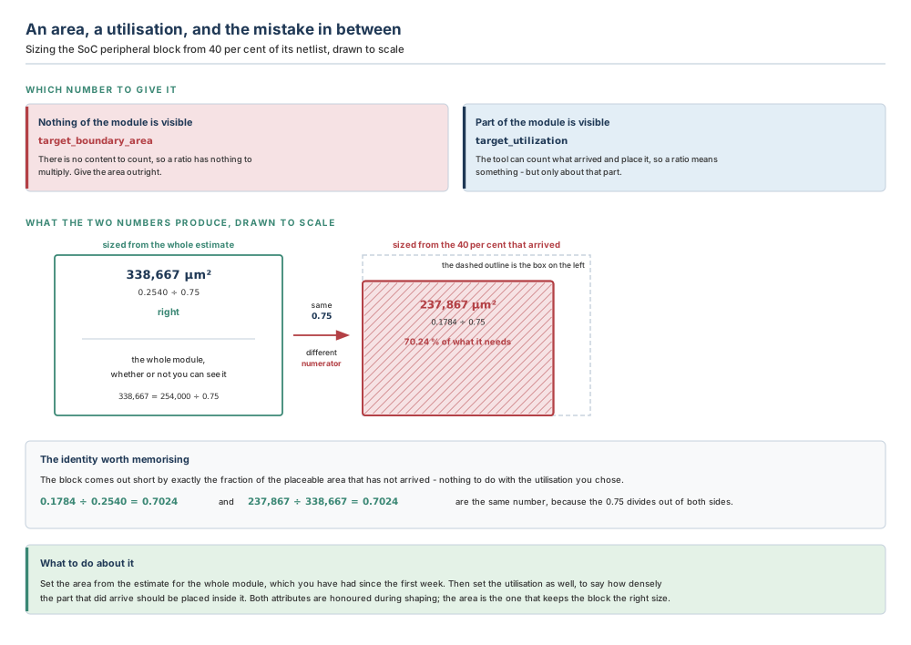
There is an identity here worth carrying away, because it makes the error predictable rather than mysterious. The block comes out short by exactly the fraction of the placeable area that has not yet arrived:
0.1784 ÷ 0.2540 = 0.7024 237,867 ÷ 338,667 = 0.7024Those are the same number, because the 0.75 divides out of both sides. The utilisation you chose has nothing to do with the size of the error. Choosing 0.65 or 0.85 instead would have produced a differently-sized block that was still 70.24 per cent of the right answer.
Notice also that the shortfall is not forty per cent, even though forty per cent of the cells arrived. The four memories were all there, and they are half the block's placeable area. Macros usually land in a netlist early — they are instantiated wrappers, not synthesised logic — which softens the ratio and makes the error harder to spot by eye. On a block with no macros at all the arithmetic is brutally direct: the boundary comes out at exactly the visible-cell fraction of the size it needs.
The rule is one sentence: the number you give a black box must describe the finished module, never the part of it you can already see.
You have the number. It is the area estimate from the first week of the project — the one Chapter 1 built and Chapter 4 sized the core from. It was computed from cell counts and macro counts for the whole module, before any netlist existed at all, which is precisely what makes it the right input here. The partial netlist is newer, more detailed, and more authoritative-looking, and it is the wrong number.
So set the area from the estimate, on every black box, including the partial ones. Then set the utilisation as well, on the partial ones, to say how densely the content that has arrived should be placed inside the boundary you fixed. On Nimbus-8's peripheral that means 338,667 µm² of boundary with 0.1784 mm² of visible content inside it, which is a local density of 0.1784 ÷ 0.338667 = 0.5268 — low, and correctly so, because the rest is coming.
5.2.7 Where the number lands
A black box's boundary area is not a private matter between you and that block. It goes into the same core arithmetic Chapter 4 set up, alongside every counted area, and it competes for the same space.
Nimbus-8's core is a square 3.20 mm on each side, so its area is 3.20 × 3.20 = 10.24 mm². The four modules whose netlists were complete at revision A occupy 3.1720 mm² for the CPU cluster, 1.18862 mm² for each of the two NPU cores, and 0.5440 mm² for the DDR PHY — 6.0932 mm² together. Add the two typed numbers and the block boundary total is 8.1486 mm², leaving 2.0914 mm² of channel, or 20.42 per cent of the core.
Now change one number and watch what happens elsewhere. Suppose the ISP had been reserved at 1.90 mm² instead of 1.716667 — a difference of 0.183 mm², about eleven per cent of the block, the kind of margin somebody adds “to be safe”. The block boundary total becomes 8.3319 mm² and the channel drops to 1.9081 mm², 18.63 per cent of the core. The ISP did not get worse; the space between every other block did, by 8.8 per cent of the channel budget, and the first symptom will be top-level congestion in a channel three blocks away.
Then the core is wrong, and the black box is the least of the problem. This is worth being clear about because it is easy to blame the mechanism. A black box faithfully transmits the area estimate into the floorplan; it neither improves nor degrades it. If the estimate was optimistic, the core Chapter 4 chose was too small, and that would have been true whether the module arrived on time or not.
What the black box does change is when you find out. A module with a netlist gets its area measured the day the netlist lands. A black box gets its area measured the day somebody deliberately compares the reserved number against the real one — which is why that comparison has to be on a schedule rather than on somebody's initiative.
5.2.8 Multiply-instantiated black boxes
Chapter 3 established that Nimbus-8's two NPU cores are the same module, NPU_CORE, instantiated twice, and that a multiply-instantiated block gets one set of constraints rather than one per instance. Black boxes work the same way, and the mechanism is the one Section 5.2.4 described: create_blackbox retargets every cell with the same reference, so a multiply-instantiated module becomes a multiply-instantiated black box in a single command. Multiply-instantiated black box support is the first item on the list of design planning operations black boxes handle.
The consequence is worth stating plainly, because it is where people try to be clever. There is one black box design, so there is one target_boundary_area, one target_utilization, and one timing model, shared by every instance. If the two instances need different areas, they are not the same module and should not have been written as one. If they need the same area but different timing — because one sits next to the memory controller and the other does not — that difference belongs at the top level, in the budgets and the boundary constraints, not in the black box.
5.3 Inputs, outputs and readiness
Black boxes sit later in a session than the previous two chapters' subjects, and they need less than you might expect. You do not need a complete netlist — that is the point — and you do not need a floorplan, although in practice you will already have one, because the sequence on a real project is: read what netlist you have, create the black boxes, then initialise the floorplan with everything sized.
| Stage | What you need | Why |
|---|---|---|
| Before identifying | A design open, with whatever netlist exists | Attributes are read off cells, and cells come from the netlist that was read. An unresolved reference still produces a cell. |
| The area estimate for every module, complete or not | This is the number a black box needs, and there is no substitute for it. See Chapter 1. | |
| The internal utilisation you intend for each block | Placeable area divided by this is the boundary area you will type. | |
| Agreement on which modules are genuinely late | A feedthrough wrapper is not a late module, and reserving area for one is a self-inflicted wound. Section 5.2.2. | |
| Before creating a timing model | Modes, corners and scenarios created | Every timing command takes -modes and -corners, and defaults to all of them. With no scenarios there is nothing for the values to attach to. See Chapter 3. |
| Clocks created, with periods | A constraint or delay given as a percentage of a clock period needs that clock to exist first. | |
| Reference library cells for the load and drive types | create_blackbox_load_type and create_blackbox_drive_type each name a buffer or inverter library cell. | |
| Afterwards you have | A black-box-typed design per module, with an area and optionally a boundary | Shaping, placement, PG routing and pin assignment can all proceed. |
| An abstract view carrying the timing model | Paths that begin or end at the black box can be timed, and the budgeter has numbers to work with. |
Preflight checklist
- The design is open and the netlist you have has been read. You know which references are unresolved.
- You have run the attribute sweep of Section 5.2.1 and written down, for every candidate, which of the five kinds it is.
- For each module you intend to black-box, you have the placeable-area estimate and the internal utilisation, and you have divided one by the other. Write the quotient down somewhere a reviewer can find it.
- You have decided, per module,
-target_boundary_areaor-boundary— a size, or a size and a shape. They are mutually exclusive. - You have checked whether any candidate is multiply instantiated, and accepted that all its instances will get the same numbers.
- You know the design's time unit. Every value in Section 5.4.2 is a bare float in that unit, and nothing will warn you if you meant a different one.
- Modes, corners, scenarios and clocks exist, if you are building timing models today.
- You have a date in the schedule for comparing every reserved area against the real one, and a named person who owns that comparison.
Item 8 is the one that gets dropped, and it is the one that turns this chapter's mechanism from a benefit into a liability. Put the reserved areas in the same file as the estimate, with the date they were set and the netlist revision they were set against. When a netlist lands, that file is a two-minute check. Without it, it is an archaeology exercise.
5.4 The guided tool walkthrough
5.4.1 create_blackbox — the module becomes a thing
Purpose. Create a black box design and update the reference for the specified cell. On a cell with an unresolved reference it creates a new empty design with the same port interface; on a logical hierarchy cell it converts the cell into a physical block and creates a design holding that hierarchy's content. Either way the new design is a black-box-typed design.
Syntax in plain English. One positional argument — the cell — and five options, which answer: what shall the design be called, what kind of black box, which library, and how big.
| Option | What it decides | Default if you say nothing |
|---|---|---|
| -new_name bb_name | The name of the new design. Only used on a cell with an unresolved reference; ignored on a successfully bound logical hierarchy cell. | a design with the same name as the cell's current reference |
| -type physical | macro | Physical black boxes are physical blocks and follow the physical-partition flow. Logical or macro types are created for unbound instances and empty hierarchies, and are then treated as any other macro and placed by the macro placer. | physical |
| -library lib_name | Which library the new design is created in. If specified, it must be one of the reference libraries for the library holding the current design. | the current library |
| -target_boundary_area area | The target area of the black box design. Mutually exclusive with -boundary. | none |
| -boundary boundary | An explicit boundary for the black box design. Mutually exclusive with -target_boundary_area. | none |
| cell | The cell whose reference is to be converted. Names, patterns or collections. Must be a logical hierarchy cell or a cell with an unresolved reference. | required |
# The ISP: missing entirely, so give it an area outright.
icc2_shell> create_blackbox -target_boundary_area 1716667 u_isp

# The SoC peripheral: partial, so the area from the whole estimate ...
icc2_shell> create_blackbox -target_boundary_area 338667 u_soc_periph

# ... and then the density for the part of it that has arrived.
icc2_shell> set_attribute -objects [get_cells u_soc_periph] \
   -name target_utilization -value 0.75

# A module whose shape is already agreed with the block owner.
icc2_shell> create_blackbox -boundary { {0 0} {1310 0} {1310 1310} \
   {0 1310} } u_isp

# A small IP wrapper you will never open: let the macro placer have it.
icc2_shell> create_blackbox -type macro -target_boundary_area 42000 \
   u_otp_fuse

# A design created in a named reference library, under a chosen name.
icc2_shell> create_blackbox -library nimbus8.dlib -new_name ISP_BB \
   -target_boundary_area 1716667 u_isp
Expected result. A new black-box-typed design; the reference of the named cell and of every other cell with that reference changed to it; and, on a logical hierarchy cell, that cell committed to a physical block.
Verification. Do not rely on the command's return value. Read the attribute instead, which also tells you the area landed:
icc2_shell> get_attribute [get_cells u_isp] design_type
black_box
icc2_shell> get_attribute -objects [get_cells u_isp] \
   -name target_boundary_area
1716667
icc2_shell> get_cells -hierarchical -filter ref_block.design_type==black_box
{u_isp u_soc_periph}
Three answers, and the third is the one that catches a mistake: if that list is longer than you expected, the command retargeted a reference you had not thought about.
Common mistakes. Supplying -target_boundary_area and -boundary together. Giving the area in the wrong unit, which produces a black box a million times too big or too small and no complaint at all. Running the command on a feedthrough wrapper. Assuming -new_name will rename a design created from a bound logical hierarchy cell, where it is ignored. Expecting one instance of a multiply-instantiated module to be converted and the others left alone.
Prerequisites. An open design containing the cell, and — for -library — a library that is a reference library of the one holding the current design. Empty, partial and missing modules can be converted either after reading the netlist or after committing the blocks.
Finding the rest. man create_blackbox, and man get_cells for the filter expression syntax.
5.4.2 The nine commands that describe timing
A black box contains no timing information by default, and the consequence is stark: any path that begins or ends at a black box is unconstrained. Not pessimistic, not approximate — absent. It does not appear in a timing report, it contributes nothing to a budget, and it cannot fail, because nothing is checking it.
The remedy is a timing model, and building one means specifying the model ports, the setup and hold constraints on the inputs, the clock-to-output path delays, and the input-to-output path delays. You can also specify the loads on input ports and the drive strength of output ports. Nine commands do this. They fall into three groups, and the groups have to happen in order.
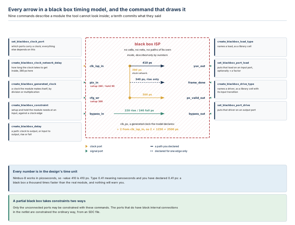
Group one: say what the ports are. set_blackbox_clock_port takes a list of ports and nothing else. It has to come first, because the network-delay, constraint and delay commands all require their clock ports to have been identified this way already. Alongside it, the electrical description of the edges: create_blackbox_load_type names a load as a buffer or inverter library cell, set_blackbox_port_load attaches it to input ports, create_blackbox_drive_type names a driver the same way, and set_blackbox_port_drive attaches it to output ports.
Group two: say what the numbers are. create_blackbox_clock_network_delay gives the delay from a clock input port into the block. create_blackbox_generated_clock declares a clock the module derives for itself. create_blackbox_constraint gives setup and hold requirements at input ports, referred to a clock edge. create_blackbox_delay gives path delays: clock to output, or input to output.
Group three: commit. One command, Section 5.4.3.
| Command and option | What it decides | Default if you say nothing |
|---|---|---|
| set_blackbox_clock_port ports | Which ports are clock ports. Nothing else takes an option here. | required before any clock-referred command |
| create_blackbox_load_type -lib_cell | The buffer or inverter library cell that acts as the load for this load type | required |
| create_blackbox_load_type name | The name that set_blackbox_port_load will use to refer to it | required |
| set_blackbox_port_load -value cap | A load capacitance directly. Mutually exclusive with -type. | none |
| set_blackbox_port_load -type name | A named load type instead of a capacitance. Mutually exclusive with -value. | none |
| set_blackbox_port_load -factor n | How many of that load type the port presents. Must be given with -type. | one of them |
| create_blackbox_drive_type -lib_cell | The buffer or inverter library cell that acts as the driver for this drive type | required |
| create_blackbox_drive_type -input_transition_rise | The rise transition time at the driver cell's input pin | zero |
| create_blackbox_drive_type -input_transition_fall | The fall transition time at the driver cell's input pin | zero |
| set_blackbox_port_drive -type name | Which drive type drives these output ports | required |
| set_blackbox_port_drive -input_transition_rise | Override the drive type's rise transition, for these ports only | the drive type's own value |
| set_blackbox_port_drive -input_transition_fall | Override the drive type's fall transition, for these ports only | the drive type's own value |
You may give a number — set_blackbox_port_load -value takes a capacitance. But a named load type is better on two counts. It is characterised: the library cell's input pin has a real capacitance at every corner, so the load you declare tracks the corner instead of being one figure applied everywhere. And it is intelligible: “four BUFX8 input pins” is a claim a designer can argue with, whereas “48 fF” is a number nobody can check. The -factor option exists so you can say “four of them” without characterising a new cell.
The same logic applies to the drive side, with one addition: a driver's strength depends on how fast its own input arrives, which is why the drive type carries an input transition time and why that time defaults to zero. A zero input transition means an optimistically fast driver, so on a real model you set it.
| Command and option | What it decides | Default if you say nothing |
|---|---|---|
| create_blackbox_clock_network_delay -value | The clock network delay inside the block, from the named clock port or black box clock | required |
| create_blackbox_clock_network_delay -max | -min | Setup analysis only, or hold analysis only. Mutually exclusive. | neither: the delay applies to both min and max |
| create_blackbox_constraint -from | The clock ports or black box clocks the constraint is measured from | required |
| create_blackbox_constraint -edge | Whether the constraint is from the rising or the falling edge of that clock | required |
| create_blackbox_constraint -to | -rise_to | -fall_to | The signal ports the constraint is for: both edges, the rising signal, or the falling signal | one of the three is required |
| create_blackbox_constraint -setup | -hold | A setup constraint, or a hold constraint. Mutually exclusive. | neither: it applies to both setup and hold |
| create_blackbox_delay -from | -rise_from | -fall_from | The originating ports or black box clocks: both edges, the rising edge only, or the falling edge only | one of the three is required |
| create_blackbox_delay -to | -rise_to | -fall_to | The destination ports, for both edges or for one | one of the three is required |
| create_blackbox_delay -max | -min | Maximum delay for setup, or minimum for hold. Mutually exclusive. | neither: the value applies to both |
| both commands: -modes | Which modes the value applies to | all modes |
| both commands: -corners | Which corners the value applies to | all corners |
| both commands: -clock | That -value is a fraction of that clock's period; the final figure is the period multiplied by the value | not specified, so -value is an absolute figure |
| both commands: -value | The number itself, absolute or fractional per -clock | required |
| create_blackbox_generated_clock -name | The generated clock's name, which must not already be in use | required |
| create_blackbox_generated_clock -master_clock | The master clock this one is derived from | required |
| create_blackbox_generated_clock -source | The master clock source pin in the design to derive the waveform from | not specified, in which case the master clock must itself have a source pin or port |
| create_blackbox_generated_clock -divide_by n | Frequency division: with 2, the generated clock's period is twice the master's. Excludes -multiply_by. | none |
| create_blackbox_generated_clock -multiply_by n | Frequency multiplication: with 3, the period is one third of the master's. Excludes -divide_by. | none |
| create_blackbox_generated_clock -invert | Inverts the generated clock signal, in the multiplication and division cases | not inverted |
| get_blackbox_generated_clocks pattern | Returns the black box generated clock objects you created, so a script can read their attributes back | required; -filter and -quiet are optional |
That last row is how the generated clock stops being write-only. get_blackbox_generated_clocks returns the object, and get_attribute on it reads back master_clock, master_source, source_pin, period and the maximum and minimum network delays — which is the only way to confirm that a divided clock came out at the period you expected rather than the one you meant to type.
-max/-min, -setup/-hold, and the mode and corner lists all default to everything. That is convenient and it is also how a hold constraint gets a setup number. If you type one create_blackbox_constraint with the setup value and no -setup, you have just declared that the hold requirement is the same as the setup requirement — usually a large, entirely fictional hold constraint that the budgeter will then respect.
The habit that avoids it: never leave -setup/-hold or -max/-min implicit on a real model. Two commands, both explicit, is four extra words and it is always right.
-clock changes the meaning of -value from an absolute figure into a fraction of that clock's period, and the final number is the product. So with clk_isp at 1,250 ps, -clock clk_isp -value 0.24 declares 300 ps.
This is worth using when the number genuinely is a fraction — “the ISP team have promised the output inside a third of the period” — because then a change of clock period carries the model with it automatically. It is worth avoiding when the number is a physical delay that does not scale with frequency, because then the automatic tracking is wrong in a way that is very hard to spot. Deciding which of the two you have is an engineering judgement about the block, not about the tool.
5.4.3 commit_blackbox_timing, and getting the model back out
Purpose. Save the black box timing information created by the commands above, by creating or updating the abstract view of the current block to include it. Until this runs, the model is inert.
Syntax in plain English. No arguments are needed. One option exists.
| Command and option | What it decides | Default if you say nothing |
|---|---|---|
| commit_blackbox_timing -convert_placement_abstract true | false | Whether to convert a placement abstract into a timing abstract carrying the black box timing data. false prevents the command from overwriting an existing placement abstract view. | true: the existing abstract view is overwritten and replaced by a compact timing abstract with black box timing |
| remove_blackbox_timing | Removes the black box timing information on the current block and updates or re-creates the abstract to match. No arguments at all. | — |
| write_blackbox_timing_script file | Writes a file of black box timing format commands that regenerate the model in this tool | mutually exclusive with -qtm_format; one of them is required |
| write_blackbox_timing_script -qtm_format | Writes Quick Timing Model files instead — one per scenario — which can generate .db files and can also be used in the PrimeTime tool | mutually exclusive with the file name |
| write_blackbox_timing_script -qtm_directory dir | Where the QTM files go. Only valid with -qtm_format. | bbt_qtm_dir |
Expected result. An abstract view for the current block containing the black box timing data. Black box timing information is stored in the design view, and when an abstract is created from a black box, specially marked cells, nets and connections are created on the fly within the abstract view. That mechanism is what enables timing on an empty or partial netlist, and it is also why newly created feedthroughs can be timed immediately without the models being rebuilt.
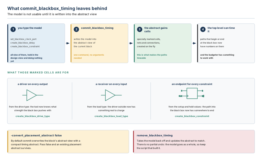
Verification. Read has_timing_model on the block, and then time something: a path that was absent from the report before the commit should be in it afterwards, with your numbers on it. If you want the model itself in a readable form, write_blackbox_timing_script writes out the commands that would rebuild it — which is also the best possible review artefact, because a reviewer can read the delays without opening the tool.
Common mistakes. Building the model and never committing it, so that every path across the block stays unconstrained and the timing report looks suspiciously short. Committing over a placement abstract somebody needed, instead of passing -convert_placement_abstract false. Expecting remove_blackbox_timing to undo one command: it removes the model as a whole, which is why the script that built it belongs in revision control.
Prerequisites. Black box timing must have been defined on the current block. For write_blackbox_timing_script, the design must already have black box timing defined.
Finding the rest. man commit_blackbox_timing, whose See Also list is the fastest route to the other eight commands.
“A partial black box has a netlist, so I can constrain all its ports with the black box commands.”
No. For a partial black box, only the unconnected ports can be constrained with black box timing constraints. The other ports on a partial black box should be constrained using SDC files, in the ordinary way, because they have real block-internal net connections that real constraints describe properly. The same restriction shows up in create_blackbox_delay: for a partial netlist, the -to ports must be ports with no block-internal net connection in the original design netlist.
Practically, this means a partial black box is constrained from two files, and the split between them is not aesthetic — it follows the netlist. Get it wrong in one direction and a command is rejected; get it wrong in the other and you have two descriptions of the same port.
5.4.4 What the model buys, and who is allowed to change it
Take one path on Nimbus-8 at revision A: out of the ISP black box on yuv_out, across the top level, into the SoC peripheral black box on cfg_in. Both ends are black boxes. Both have models. The clock is clk_isp at 800 MHz.
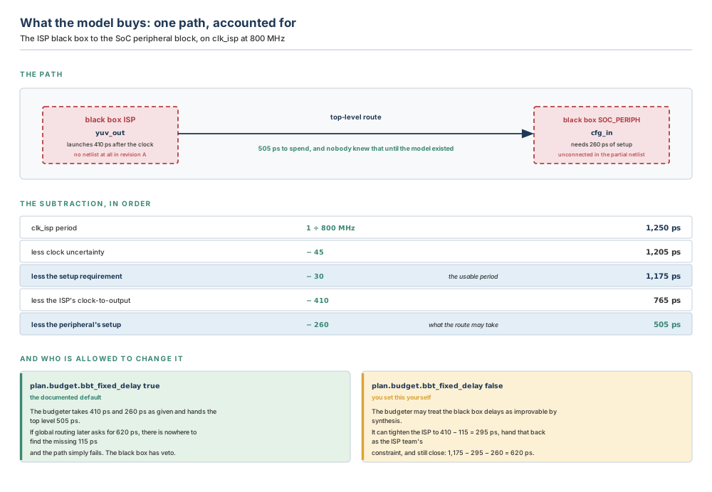
The arithmetic is Chapter 3's, with two black box numbers added. A period of 1,250 ps, less Nimbus-8's 45 ps of clock uncertainty and 30 ps setup requirement, gives 1,175 ps of usable period. The ISP's model declares 410 ps from clock to output; the peripheral's declares 260 ps of setup at its input. What is left for the top-level route is
1,175 − 410 − 260 = 505 psand the reason that number matters is not its value. It is that there is a number. Before the models existed, this path did not appear in any report; after them, it has a budget, and if the route turns out to need more than 505 ps somebody will be told.
Which raises the question of who may change it. When generating timing budgets, the tool maintains the timing you specified with the black box timing commands. That is the default, and it is a strong one: your 410 ps is a fact the budgeter works around. To allow the budgeter to adjust the black box timing budgets instead, set the application option:
icc2_shell> set_app_options -name plan.budget.bbt_fixed_delay -value false
plan.budget.bbt_fixed_delay false
Suppose global planning later reports that the route this path needs cannot be done in less than 620 ps. With fixed delays, there is nowhere to find the missing 115 ps and the path fails; the black box has an effective veto over a route it knows nothing about. With the option set false, the budgeter may tighten the ISP's model to 410 − 115 = 295 ps, hand that figure to the ISP team as their constraint, and close the path: 1,175 − 295 − 260 = 620 ps.
Which setting is right depends entirely on where the 410 ps came from, and that is a question about your project rather than about the tool.
If the number is a commitment — the ISP team measured it on the previous generation, or contracted to it — leave the default alone. It is a fact, and a budgeter that quietly improves facts produces budgets nobody can meet.
If the number is your own estimate, standing in for a module nobody has synthesised, then it is exactly the kind of thing synthesis might improve, and forbidding the budgeter from touching it makes your guess more authoritative than the router's measurement. Set it false, and treat the tightened figure as a question for the block owner rather than as a decision.
Either way, write down which of the two you chose and why. This is a two-word option that changes who owns a timing failure.
5.4.5 The power intent
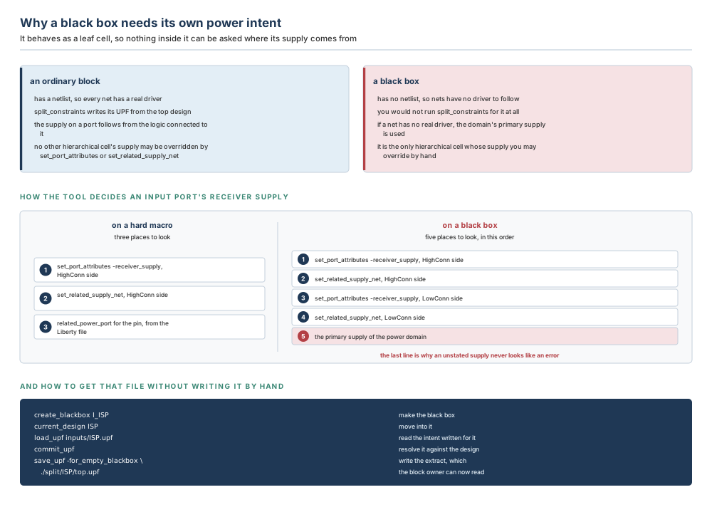
The UPF constraints for black boxes are specified differently from those for normal blocks, and the reason is structural: black boxes act as leaf cells. A block's UPF describes what is inside the block. A black box has no inside, so its UPF describes its context, in terms of the top level — and it must also define the receiver supply information for the block's input ports.
Three consequences follow, and each one is a thing to do or not do.
Do not run split_constraints for it. You would not typically run split_constraints to generate UPF constraints for black boxes or empty modules. Chapter 3 built the whole splitting flow, and this is the one case it is not for: splitting derives a block's constraints from the top-level design's view of it, which requires the block to have content the derivation can follow.
Know what happens when nothing is stated. If a net does not have a real driver, the primary supply for the domain is used. That is a sensible fallback and it is also silent. A black box input port whose receiver supply nobody declared will not produce an error; it will produce a port powered from the domain primary, which may well be wrong and will certainly not be flagged.
Use the override, because here you are allowed to. Black boxes are the only hierarchical cells where set_port_attributes or set_related_supply_net can be used to override the supply information. On any other hierarchical cell that override is not available; on a black box it is the mechanism.
The priority order is worth having in front of you, because it is longer for a black box than for a hard macro. When the tool considers power intent logic insertion outside a hard macro, the receiver supply of an input port is determined in this order: a set_port_attributes -receiver_supply at the HighConn side of the port; then a set_related_supply_net at the HighConn side; then any related_power_port information for the pin from the Liberty file. Three steps, and the third comes from a library.
Outside a black box cell there is no library, so the order has five steps: set_port_attributes -receiver_supply at the HighConn side; set_related_supply_net at the HighConn side; set_port_attributes -receiver_supply at the LowConn side; set_related_supply_net at the LowConn side; and finally the primary supply of the power domain. The two extra steps exist because a black box has an inside you may write constraints for even though it has no content, and the last step is the silent default above.
Rather than write the file by hand, extract it. The UPF for black boxes can be written specifically for the black box or extracted from an existing design with save_upf -for_empty_blackbox:
# Make the black box, move into it, read its intent, resolve, extract.
icc2_shell> create_blackbox I_ISP
icc2_shell> current_design ISP
icc2_shell> load_upf inputs/ISP.upf
icc2_shell> commit_upf
icc2_shell> save_upf -for_empty_blackbox ./split/ISP/top.upf
Note the destination. ./split/ISP/top.upf is the same directory layout Chapter 3 established, and top.upf is the same file name split_constraints writes for an ordinary block. The block owner's flow does not change; only the way the file was produced does. -for_empty_blackbox cannot be combined with -format, -force_reference, -force_no_reference, -include or -exclude.
One more instruction, and it is easy to miss because it sounds like advice: you should create abstracts for black boxes in your design. Doing so creates black box timing cells, which — in addition to providing drive and load information for outputs and inputs — also provide drivers and receivers on the net. Those drivers and receivers are what let multivoltage commands such as check_mv_design perform as expected.
So a black box without an abstract does not merely lack timing. It lacks the objects the multivoltage checker looks for, which means check_mv_design is not in a position to check the very supply connections this section is about. The check will run. It will not find what is not there.
5.5 The worked example: Nimbus-8 at revision A
One continuous example, from the attribute sweep to a committed model. Every number in it has appeared already; this section is where they are produced rather than quoted.
Step 1 — find out what you are holding
# What did not resolve?
icc2_shell> set cands [get_cells -hierarchical -filter is_hierarchical==true]
icc2_shell> foreach_in_collection c $cands {
   set n [get_object_name $c]
   puts [format "%-16s unbound %-6s std %-8s macro %-4s shadow %-6s only %s" $n \
      [get_attribute -objects $c -name is_unbound] \
      [get_attribute -objects $c -name hierarchy_std_cell_count] \
      [get_attribute -objects $c -name hierarchy_hard_macro_count] \
      [get_attribute -objects $c -name hierarchy_has_shadow_netlist] \
      [get_attribute -objects $c -name hierarchy_has_shadow_netlist_only]]
}
The sweep returns six hierarchical cells. Four of them report cell counts in the millions and need nothing from this chapter. The other two are the subject:
| Cell | unbound | std cells | macros | shadow | only | Reading |
|---|---|---|---|---|---|---|
| u_cpu_cluster | false | 4,600,000 | 24 | true | false | complete |
| u_npu_core_0 | false | 1,450,000 | 12 | true | false | complete |
| u_npu_core_1 | false | 1,450,000 | 12 | true | false | complete, same reference as core 0 |
| u_isp | true | 0 | 0 | false | — | missing: no module statement at all |
| u_soc_periph | false | 144,000 | 4 | true | false | partial: the memories and 40 % of the cells |
| u_cfg_tie | false | 0 | 0 | false | false | tie-off: a wrapper. Leave it alone. |
Three readings, three different actions. u_isp and u_soc_periph become black boxes. u_cfg_tie does not: it holds configuration straps at constants, it has no cells, and reserving area for it would take space from every other block for nothing. It is in the table only because the sweep found it, and because the first instinct on seeing a zero cell count is to reach for create_blackbox.
Run this sweep as a script and keep its output. It is the record of what the netlist looked like on the day you planned, and it is what turns the later comparison — reserved area against real area — from an argument into a diff. On a real project the file is called something like bb_survey_revA.log and it lives beside the floorplan.
Step 2 — work out the two numbers, on paper, before typing anything
Both come from Chapter 1's estimate and Chapter 1's internal utilisation of 0.75. Neither comes from the netlist, and for the peripheral block that is a deliberate refusal to use newer information.
# The ISP. 1.85 M cells at 0.350 um2, plus 20 SRAM at 0.0320 mm2.
1.85e6 x 0.350 um2 = 647,500 um2 = 0.6475 mm2
20 x 0.0320 mm2                  = 0.6400 mm2
placeable                        = 1.2875 mm2
boundary = 1.2875 / 0.75         = 1.716667 mm2 = 1,716,667 um2

# The SoC peripheral. 0.36 M cells, 4 SRAM. The WHOLE module.
0.36e6 x 0.350 um2 = 126,000 um2 = 0.1260 mm2
4 x 0.0320 mm2                   = 0.1280 mm2
placeable                        = 0.2540 mm2
boundary = 0.2540 / 0.75         = 0.338667 mm2 =   338,667 um2
In words, because a number you can say out loud is a number you can be challenged on: the ISP is 0.6475 mm² of standard cells and 0.6400 mm² of memories, so 1.2875 mm² of placeable area, so a boundary of 1.716667 mm². The peripheral is 0.1260 mm² of cells and 0.1280 mm² of memories, so 0.2540 mm² placeable, so a boundary of 0.338667 mm².
Check each one backwards before it goes anywhere: 1.716667 × 0.75 = 1.2875, and 0.338667 × 0.75 = 0.2540. Both recover the placeable areas they came from, so neither is a typing error.
And check the third number, the one nobody asks for. The two boundary areas together are 2.055334 mm². Chapter 4's core is 10.24 mm², the four complete blocks and the DDR PHY occupy 6.0932 mm², so the block boundary total is 8.1486 mm² and the channel left is 2.0914 mm² — 20.42 per cent of the core. That is comfortable. Had the ISP been reserved at 1.90 mm² “for safety”, the channel would have dropped to 1.9081 mm², 18.63 per cent, and the safety margin would have been paid for out of somebody else's routing space.
Step 3 — create the black boxes
# Missing: an area, and nothing else to say.
icc2_shell> create_blackbox -target_boundary_area 1716667 u_isp

# Partial: the same kind of area, from the whole estimate ...
icc2_shell> create_blackbox -target_boundary_area 338667 u_soc_periph

# ... and then a density for the 40 per cent that is visible.
icc2_shell> set_attribute -objects [get_cells u_soc_periph] \
   -name target_utilization -value 0.75

# Read all three numbers back. Never quote what you typed.
icc2_shell> get_attribute -objects [get_cells u_isp] \
   -name target_boundary_area
1716667
icc2_shell> get_cells -hierarchical \
   -filter ref_block.design_type==black_box
{u_isp u_soc_periph}
icc2_shell> report_app_options plan.budget.bbt_fixed_delay
The second answer is the audit. Two cells, which is two more than before and no more than intended — if u_cfg_tie had appeared in that list, somebody had reached for the command too quickly.
Step 4 — give the ISP a timing model
Nimbus-8's ISP runs on clk_isp at 800 MHz, exactly half the CPU frequency established in Chapter 1, so the period is 1,250 ps against clk_cpu's 625 ps. The design's time unit is 1 ps, which is why every value below is a whole number of hundreds rather than a decimal fraction.
# The mode, corner and scenario grid from Chapter 3, and the clock.
icc2_shell> create_mode func
icc2_shell> create_corner ss_125c
icc2_shell> create_scenario -mode func -corner ss_125c
icc2_shell> create_clock -name clk_isp -period 1250 [get_ports clk_isp_in]

# --- group one: what the ports are, electrically -------------------
icc2_shell> set_blackbox_clock_port [get_ports clk_isp_in]

icc2_shell> create_blackbox_load_type \
   -lib_cell [get_lib_cells stdcell/BUFX8] lt_isp
icc2_shell> create_blackbox_drive_type \
   -lib_cell [get_lib_cells stdcell/BUFX16] \
   -input_transition_rise 12 -input_transition_fall 12 dt_isp

icc2_shell> set_blackbox_port_load -type lt_isp -factor 4 \
   [get_ports pix_in*]
icc2_shell> set_blackbox_port_drive -type dt_isp \
   [get_ports {yuv_out* frame_done px_valid_out}]
# --- group two: the numbers ----------------------------------------
# The clock takes 380 ps to spread inside the block.
icc2_shell> create_blackbox_clock_network_delay -value 380 clk_isp_in

# Setup and hold at the pixel inputs. Two commands, both explicit.
icc2_shell> create_blackbox_constraint -setup -edge rise \
   -from clk_isp_in -to [get_ports pix_in*] -value 260
icc2_shell> create_blackbox_constraint -hold -edge rise \
   -from clk_isp_in -to [get_ports pix_in*] -value 90

# The configuration write is a fraction of the period, not a delay:
# 0.24 x 1250 = 300 ps, and it tracks the clock if the clock changes.
icc2_shell> create_blackbox_constraint -setup -edge rise \
   -from clk_isp_in -to cfg_wr -clock clk_isp -value 0.24

# Clock to output. Late corner first, then the early value.
icc2_shell> create_blackbox_delay -max -from clk_isp_in -to yuv_out \
   -value 410
icc2_shell> create_blackbox_delay -min -from clk_isp_in -to yuv_out \
   -value 180
icc2_shell> create_blackbox_delay -max -rise_from clk_isp_in \
   -to frame_done -value 340

# A combinational bypass, different in each direction.
icc2_shell> create_blackbox_delay -max -rise_from bypass_in \
   -rise_to bypass_out -value 220
icc2_shell> create_blackbox_delay -max -fall_from bypass_in \
   -fall_to bypass_out -value 240

# A clock the ISP makes for itself: 2 x 1250 = 2500 ps, 400 MHz.
icc2_shell> create_blackbox_generated_clock -name clk_px -divide_by 2 \
   -source clk_isp_in -master_clock clk_isp
icc2_shell> create_blackbox_delay -max -from clk_px \
   -to px_valid_out -value 300
# --- group three: make it real -------------------------------------
icc2_shell> commit_blackbox_timing
Two habits in that script are worth naming. Every create_blackbox_delay carries -max or -min and every create_blackbox_constraint carries -setup or -hold, even though both default to applying to everything — because a setup number silently doubling as a hold number is a fictional constraint the budgeter will honour. And no command carries -modes or -corners, which means all of these values apply to every mode and every corner in the design. On a one-corner script that is exactly right. On the full Chapter 3 grid of two modes and two corners it is not: the ISP at ff_m40c is not a 410 ps block. A second line fixes it —
icc2_shell> create_blackbox_delay -max -corners ff_m40c \
   -from clk_isp_in -to yuv_out -value 240
— and the general rule is that a model with one number per path is a first draft, not a deliverable.
Step 5 — check that it landed, and read the budget off it
# Did the commit reach the abstract?
icc2_shell> get_attribute -objects [get_cells u_isp] \
   -name has_timing_model
# Write the model out, and read it as a reviewer would.
icc2_shell> write_blackbox_timing_script isp_bbt_revA.tcl
# And for a signoff tool that wants QTM instead:
icc2_shell> write_blackbox_timing_script -qtm_format \
   -qtm_directory qtm_isp_revA
Now the arithmetic of Section 5.4.4, done on the real numbers. The path leaves the ISP on yuv_out and arrives at the peripheral's cfg_in, which is one of the ports with no block-internal connection in the partial netlist — which is why a black box constraint on it is legal at all.
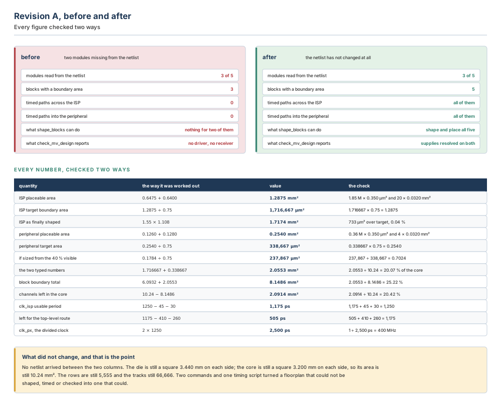
| Quantity | Worked out as | Value | Reached the other way |
|---|---|---|---|
clk_isp period | 1 ÷ 800 MHz | 1,250 ps | 1 ÷ 1,250 ps = 800 MHz |
| Usable period | 1250 − 45 − 30 | 1,175 ps | 1175 + 45 + 30 = 1250 |
| Declared by the ISP model | clk to yuv_out | 410 ps | read back from write_blackbox_timing_script |
| Declared by the peripheral model | setup at cfg_in | 260 ps | read back the same way |
| Left for the top-level route | 1175 − 410 − 260 | 505 ps | 505 + 410 + 260 = 1175 |
| If routing needs 620 ps | 620 − 505 | 115 ps short | 1175 − 620 − 260 = 295 |
| ISP model, if the budgeter may adjust | 410 − 115 | 295 ps | 1175 − 295 − 260 = 620 |
clk_px, divided by 2 | 2 × 1250 | 2,500 ps | 1 ÷ 2,500 ps = 400 MHz |
| The percentage-form constraint | 0.24 × 1250 | 300 ps | 300 ÷ 1250 = 0.24 |
Step 6 — the power intent, and the abstract
# Extract the black box UPF rather than writing it.
icc2_shell> create_blackbox I_ISP
icc2_shell> current_design ISP
icc2_shell> load_upf inputs/ISP.upf
icc2_shell> commit_upf
icc2_shell> save_upf -for_empty_blackbox ./split/ISP/top.upf

# State the receiver supply, because the fallback is silent.
icc2_shell> set_port_attributes -ports [get_ports pix_in*] \
   -receiver_supply VDD_ISP

# Create abstracts, so the multivoltage check has objects to check.
icc2_shell> create_abstract -blocks {ISP SOC_PERIPH}
icc2_shell> check_mv_design -interface_only
That last pair is the step teams skip, and Section 5.4.5 explained the consequence: without abstracts there are no black box timing cells, so there are no drivers and receivers on the nets, so check_mv_design runs and finds nothing. A clean report from a check that had nothing to look at is the most dangerous artefact in this chapter.
Engineering judgement — the three calls that were not the tool's to make
Refusing the newer number. The peripheral's area came from the first-week estimate rather than from the netlist on the disk. That is the right call, and it is uncomfortable, because the netlist is real and the estimate is not. The test to apply is not “which number is more accurate?” but “which number describes the finished module?” — and only one of them was trying to.
Not black-boxing the tie-off. u_cfg_tie matched a documented black box pattern and was left alone anyway, because the pattern tells you what a module contains, not what to do about it. Reserving area for a module with no cells is a cost with no benefit.
Leaving plan.budget.bbt_fixed_delay at its default. The ISP's 410 ps came from the previous generation of the same block, measured, not guessed. A measured number should not be quietly improved by a budgeter, so the default stands. Had the number been an estimate, the honest setting would have been false — and the tightened figure would have gone to the ISP team as a question.
5.6 Failure modes and how to recognise them
Ten ways this goes wrong. Only two of them produce a message, which is why the “how you notice” column is the important one.
| # | What went wrong | How you notice | What to do |
|---|---|---|---|
| 1 | The area was computed from the partial netlist instead of the estimate. | Nothing at all. The block shapes, the visible cells place with room to spare, and the floorplan looks healthier than the real one will. Weeks later the real netlist arrives 30 % bigger. | Recompute from the Chapter 1 estimate: placeable ÷ internal utilisation. Compare against the reserved figure and re-floorplan if the gap is more than a few per cent. |
| 2 | A timing value was given in the wrong unit — 0.41 meaning nanoseconds, in a design whose time unit is 1 ps. | Enormous positive slack on every path through the block, and a black box that appears to be a thousand times faster than any real logic could be. | Check the design's time unit, then read the model back with write_blackbox_timing_script and look at the magnitudes. A clock-to-output faster than a single gate is the tell. |
| 3 | The model was built but commit_blackbox_timing was never run. | The timing report is suspiciously short. Paths that ought to cross the black box are absent rather than failing, and has_timing_model is false. | Run the commit. Then confirm the paths appear, because an absent path and a passing path look identical in a summary line. |
| 4 | -setup/-hold or -max/-min was left implicit, so one number became both. | Hold violations at the block boundary that no amount of buffering fixes, because the hold requirement is a setup number in disguise. | Split every constraint and every delay into two explicit commands. Re-read the model and confirm each path has two different numbers. |
| 5 | create_blackbox was run on a feedthrough or tie-off wrapper. | The channel area is tighter than the arithmetic predicted, and a block on the floorplan has a boundary with nothing inside it. | Re-run the attribute sweep. A module with zero cell and macro counts needs no area; take the reservation back out and re-shape. |
| 6 | One instance of a multiply-instantiated module was converted, in the belief the others were untouched. | Every instance of that module is now a black box, and all of them carry the area chosen for the first one. | Accept it, or reconsider the hierarchy. One reference means one black box; instance-specific differences belong in the top-level budgets. |
| 7 | The commit overwrote a placement abstract somebody needed. | Macro placement inside a partial black box has gone, and the abstract is now a compact timing abstract. | Re-create the placement, then commit again with -convert_placement_abstract false. On a partial black box, make this the default habit. |
| 8 | No abstract was created for the black box. | A clean multivoltage report. check_mv_design ran, found no violations, and had no black box timing cells to look at — so no drivers, no receivers, nothing to check. This is the most misleading symptom in the chapter: the report is not wrong, it is empty. | Run create_abstract on every black box, then run check_mv_design again and expect the violation count to rise. A number going up is the evidence that the check is now real. |
| 9 | The receiver supply was never stated on the black box's input ports. | Nothing. The domain's primary supply is used, silently, because a net with no real driver falls back to it. A missing level shifter surfaces at implementation. | State it, with set_port_attributes -receiver_supply or set_related_supply_net — the override that only black boxes allow. Then re-run the interface check. |
| 10 | plan.budget.bbt_fixed_delay was left true while the delays were guesses. | A top-level route the budgeter cannot close, reported as a global planning problem in a channel, with no indication that a black box estimate is the constraint. | Decide whether each number was measured or guessed. Set the option false where they were guessed, and take the tightened figures to the block owners. |
Four chapters in, the same shape keeps recurring, and Chapter 5 gives it its sharpest form. Chapter 2's misleading symptom was a setup file that had not been read, so a session looked configured. Chapter 3's was a constraint file written for a block that was never asked for it. Chapter 4's was a re-run that silently deleted routing. This chapter's is a clean report from a check with nothing to check.
The pattern is always absence reported as success. A tool cannot tell you that it did not check something it was never given; the summary line says zero violations either way. So the habit that catches all four is the same, and it is worth stating as a rule: after a check passes, confirm that it examined what you think it examined. Count the paths in the timing report. Count the violations before and after creating abstracts. Count the files split_constraints wrote. A zero you have not accounted for is not a pass; it is a question.
5.7 Hands-on mini lab
Goal. Take the design Eridanus-6 from a netlist two modules short to a floorplan that can be shaped, timed and multivoltage-checked — and quantify, twice, what the wrong sizing choice would have cost.
Given.
| Item | Value |
|---|---|
| Modules in the netlist | u_cpu, u_gpu, u_vpu, u_aud, u_dbg_ft |
u_vpu (module VPU) | is_unbound true, zero cells, zero macros, no shadow netlist |
u_aud (module AUDIO) | is_unbound false, 200,000 cells, 5 macros, shadow netlist true, _only false |
u_dbg_ft (module DBG_FT) | is_unbound false, zero cells, zero macros, shadow netlist true, _only true |
Estimate for VPU | 2.40 M standard cells, 15 SRAM macros |
Estimate for AUDIO | 0.80 M standard cells, 5 SRAM macros |
| Library figures | 0.400 µm² per standard cell, 0.040 mm² per SRAM macro |
| Internal utilisation for both blocks | 0.80 |
| Fastest clock | clk_vid, 500 MHz |
| Clock uncertainty / setup requirement | 50 ps / 25 ps |
| Constraint files are quoted in | picoseconds |
VPU's promised clock-to-output | 600 ps, measured on the previous generation |
| Setup needed at the receiving block's input | 300 ps |
Tasks.
- Classify all three candidates. Using only the attributes in the table, say which of the five kinds each of
u_vpu,u_audandu_dbg_ftis, and which attribute settled each case. Then say which of the three you will not make a black box, and why. - Compute the two areas, twice each. Work out the target boundary area for
VPUand forAUDIOfrom the estimates, forwards and then backwards. Give both in mm² and in µm². - Quantify the trap. Work out what
AUDIOwould have come out at had you set onlytarget_utilization 0.80and let the tool size it from the 200,000 cells and 5 macros it can see. Express the result as a percentage of the right answer, and then verify that percentage a second way, from the placeable areas alone. - Write the create commands. Two
create_blackboxcalls and oneset_attribute. Then write the two verification commands you would run immediately afterwards, and say what each answer would have to be for you to continue. - Do the timing arithmetic. Compute
clk_vid's period, the usable period after uncertainty and setup, and how much is left for the top-level route once the black box's 600 ps and the receiver's 300 ps are taken out. Check the subtraction by adding back. - Write four timing commands. One that identifies the clock port; one that declares the clock-to-output delay for setup analysis only; one that declares a setup constraint at an input as 15 per cent of
clk_vid's period, and states what that is in picoseconds; and one that declares a generated clock divided by four, with its period and frequency. - Decide the budget question.
VPU's 600 ps was measured on the previous generation. State which way you would setplan.budget.bbt_fixed_delay, and give the one-sentence reason. Then say what would change if the 600 ps had been your own guess. - Name the check that will lie to you. Say which command will report zero violations even when the supplies are wrong, why, and the one command that has to be run first for its answer to mean anything.
Expected observations.
1. u_vpu is missing — settled by is_unbound true, and nothing else needs reading. u_aud is partial — settled by the two hierarchy counts being above zero. u_dbg_ft is a feedthrough — settled by hierarchy_has_shadow_netlist_only true with zero cells: it carries debug signals across the hierarchy and contains nothing. It should not be made a black box, because it has no cells and therefore no area to reserve; giving it a boundary would take channel area from every other block for nothing.
2. VPU: 2.40 M × 0.400 µm² = 0.960 mm² of cells, 15 × 0.040 = 0.600 mm² of macros, so 1.560 mm² placeable and 1.560 ÷ 0.80 = 1.950 mm² = 1,950,000 µm². Backwards: 1.950 × 0.80 = 1.560. AUDIO: 0.320 + 0.200 = 0.520 mm² placeable, and 0.520 ÷ 0.80 = 0.650 mm² = 650,000 µm². Backwards: 0.650 × 0.80 = 0.520. The two typed numbers together are 2.600 mm².
3. Visible content: 200,000 × 0.400 µm² = 0.080 mm² of cells plus all 0.200 mm² of macros = 0.280 mm². At 0.80 that gives 0.280 ÷ 0.80 = 0.350 mm² = 350,000 µm², which is 350,000 ÷ 650,000 = 53.85 per cent of the right answer — a deficit of 300,000 µm², or 46.15 per cent. Second route: 0.280 ÷ 0.520 = 0.5385, the same figure, because the 0.80 divides out of both sides. Note that only a quarter of the cells arrived but the block came out at 54 per cent rather than 25 per cent, because all five memories were already there.
4. create_blackbox -target_boundary_area 1950000 u_vpu; create_blackbox -target_boundary_area 650000 u_aud; set_attribute -objects [get_cells u_aud] -name target_utilization -value 0.80. Verification: get_attribute -objects [get_cells u_vpu] -name target_boundary_area must return 1950000, and get_cells -hierarchical -filter ref_block.design_type==black_box must return exactly two cells. If it returns three, u_dbg_ft was converted by mistake.
5. Period 1 ÷ 500 MHz = 2,000 ps. Usable 2000 − 50 − 25 = 1,925 ps. Left for the route 1925 − 600 − 300 = 1,025 ps. Check: 1025 + 600 + 300 = 1925, and 1925 + 50 + 25 = 2000.
6. set_blackbox_clock_port [get_ports clk_vid_in]; create_blackbox_delay -max -from clk_vid_in -to vid_out -value 600; create_blackbox_constraint -setup -edge rise -from clk_vid_in -to cfg_in -clock clk_vid -value 0.15, which is 0.15 × 2000 = 300 ps; and create_blackbox_generated_clock -name clk_disp -divide_by 4 -source clk_vid_in -master_clock clk_vid, giving 4 × 2000 = 8,000 ps, which is 125 MHz.
7. Leave it at its default, true: the 600 ps was measured on real silicon, so it is a fact, and a budgeter that improves facts produces budgets nobody can meet. Had it been a guess, the honest setting would be false — the guess is exactly the kind of number synthesis might beat, and forbidding the budgeter to touch it would make your estimate more authoritative than the router's measurement.
8. check_mv_design. It reports zero violations on a black box with no abstract because there are no black box timing cells, and therefore no drivers and receivers on the nets for it to examine. create_abstract has to run first — and the evidence that the check is now real is that the violation count goes up.
Do task 3 before task 2 on your second pass through this lab, and notice how much more plausible the wrong answer feels when you compute it first. 350,000 µm² for a block with 200,000 cells and five memories in it is not an absurd number. That is the whole difficulty: the trap in Section 5.2.6 does not produce a figure that looks wrong. It produces a figure that looks carefully derived, because it was — from the wrong netlist.
5.8 Interview preparation
Sixteen questions, grouped by level. Answer each one out loud before reading the model answer. Black boxes come up often in interviews for a specific reason: the topic is a fast test of whether a candidate understands that the tool will do exactly what it is told and check none of it.
Beginner
BEGINNER
Q1. What is a black box, and why would you want one?
A module that has no netlist, has only a partial netlist, or is not bound to a higher-level module. You use black boxes to continue design planning without requiring a complete netlist for all modules. Two additions make the answer complete. Black boxes are supported for both physical and timing purposes, and at all stages of design planning — so this is not a stub that gets a script past a missing file, it is a planning object that shaping, PG routing, pin assignment, abstract creation and budgeting all handle. And only physical hierarchies can be black boxes: a logical hierarchy cell has to become a physical block first, which create_blackbox does as part of its work.
What is being tested: whether you know the three-clause definition or only the first clause. “A module with no netlist” misses partial black boxes, which are the interesting half of the topic.
BEGINNER
Q2. How do you find the black boxes in a design?
Black boxes can be identified by retrieving cells with a black_box attribute set to true. For black boxes created with create_blackbox, check the module's design_type attribute: get_cells -hierarchical -filter ref_block.design_type==black_box, or get_attribute on a named cell. Two related attributes cover the cases the filter does not: is_empty for empty hierarchies and is_logical_black_box for macro-style black boxes. The GUI also annotates them in the Hierarchy Browser and the Properties Editor, which is the quick visual confirmation that you converted what you meant to.
What is being tested: whether you can distinguish “list them all” from “is this one”. They are different commands and interviewers ask for both.
BEGINNER
Q3. What does create_blackbox do?
It creates a black box physical hierarchy for the cell and updates the cell's reference. On a cell with an unresolved reference it creates a new empty design with the same port interface as the reference; on a logical hierarchy cell it converts the cell into a physical block and creates a design holding that hierarchy's content. The new design is a black-box-typed design. The part candidates miss is the reach: the reference of the named cell and of every other cell with the same reference is changed, including cells in designs linked as child designs and designs linked with the same unresolved reference. One command, every instance.
What is being tested: whether you know the command is global rather than local. A candidate who thinks it converts one instance will eventually be surprised by a multiply-instantiated module.
BEGINNER
Q4. Where does a black box's port interface come from, if the module does not exist?
From the instantiation. When the specified cell has an unresolved reference, create_blackbox creates a new empty design with the same port interface as the unresolved reference of the cell. This is the mechanism that makes everything else in the chapter possible. A Verilog instantiation names every port it connects, so even with the module body entirely absent the interface is fully known — which is why a black box can carry a meaningful timing model, take a pin assignment, and have feedthroughs created through it.
What is being tested: whether you have thought about it at all. Most candidates have not, and the question separates people who have used black boxes from people who have read about them.
Intermediate
INTERMEDIATE
Q5. Classify the five kinds of black box and say which attribute settles each case.
Missing, empty, partial, feedthrough and tie-off. is_unbound true settles missing. With is_unbound false, the standard-cell and hard-macro counts separate empty from partial. With both counts zero, hierarchy_has_shadow_netlist distinguishes a tie-off (false) from something carrying wiring (true), and hierarchy_has_shadow_netlist_only true confirms a feedthrough. Missing modules have no module statement in the Verilog; empty ones have the statement and no content; partial ones have an incomplete set of cells; feedthroughs have net connections between input and output ports and no cells; tie-offs have only output ports tied to a logical value.
What is being tested: whether you can give a reading order. A candidate who lists five names and five attributes without pairing them has memorised a table; one who says “is_unbound first, because true ends the question” has used it.
INTERMEDIATE
Q6. How do you tell a black box how big it is, and what happens to that number?
Two ways. create_blackbox -target_boundary_area specifies the target area, and it is mutually exclusive with -boundary, which gives an explicit boundary instead. To change an area already set, set the target_boundary_area attribute directly on the black box cell. For black boxes from a partial Verilog netlist you can additionally set target_utilization. Both attributes are honoured by shape_blocks during block shaping. What happens to the number is the part worth volunteering: it goes into the same core arithmetic as every counted area, so it competes for channel space with every other block. On a real design a quarter of the block area can come from typed numbers, and nothing downstream distinguishes them from measured ones.
What is being tested: whether you see the number as a local property of one block or as a claim on shared space. Interviewers who have been bitten by this ask the follow-up: “so what happens if you add ten per cent for safety?”
INTERMEDIATE
Q7. Walk me through creating a black box timing model.
Three steps. Define the clock ports, drive and load, with set_blackbox_clock_port, set_blackbox_port_drive and set_blackbox_port_load. Set the clock network delay, pin-to-pin delays, and setup and hold constraints, with create_blackbox_clock_network_delay, create_blackbox_constraint, create_blackbox_delay, create_blackbox_drive_type and create_blackbox_load_type. Then commit the model to the black box with commit_blackbox_timing. Say what you are specifying, not just which commands: the model ports, the setup and hold constraints on the inputs, the clock-to-output path delays and the input-to-output path delays, plus optionally the loads on inputs and the drive strength of outputs. The clock ports come first because everything referred to a clock edge requires them.
What is being tested: whether the commit is in your answer. Leaving it out is the single most common omission, and it is also the most common real-world mistake.
INTERMEDIATE
Q8. What does commit_blackbox_timing actually change?
It saves the black box timing information you created and creates or updates the abstract view of the current block to include it. Black box timing information is stored in the design view; when an abstract is created from a black box, specially marked cells, nets and connections are created on the fly within the abstract view. Those marked objects are the point. A black box has no flip-flop for a path to end at and no buffer to drive one, so the commit creates the objects the timer needs. That approach enables timing on an empty or partial netlist and lets newly created feedthroughs be timed immediately without recreating the models. By default the command overwrites the existing abstract view with a compact timing abstract; -convert_placement_abstract false stops it replacing a placement abstract you still need.
What is being tested: whether you know why the abstract matters, which is the setup for Q14.
INTERMEDIATE
Q9. Compare target_boundary_area and target_utilization. When is each right?
The area is a size; the utilisation is a ratio the tool multiplies by content it can count. So on a missing or empty module the utilisation has no numerator and cannot produce a size at all — the area is the only option. On a partial netlist the utilisation works, and that is exactly where it is dangerous. The trade is worth quantifying. If forty per cent of a block's standard cells have arrived and all its memories have, a target utilisation sizes the block from that visible content, and the boundary comes out at the visible fraction of the placeable area — around seventy per cent of what the module needs, with no warning of any kind. The right practice is to set the area from the whole-module estimate on every black box, and to add the utilisation on partial ones to say how densely the visible content should sit inside that boundary.
What is being tested: a genuine trade-off, and whether you can name the failure quantitatively. “Utilisation for partial blocks” is the half-answer; the other half is why it under-sizes them.
INTERMEDIATE
Q10. What is different about UPF for a black box?
Black boxes act as leaf cells, so their UPF constraints describe the context in terms of the top level rather than the block's internals, and the black box UPF also defines the receiver supply information for the block input ports. You would not typically run split_constraints to generate UPF for black boxes or empty modules, and if a net does not have a real driver the primary supply for the domain is used. One permission and one instruction complete the answer. Black boxes are the only hierarchical cells where set_port_attributes or set_related_supply_net can be used to override the supply information. And you should create abstracts for black boxes, because that creates black box timing cells which provide drivers and receivers on the net and so let commands such as check_mv_design perform as expected.
What is being tested: whether you can explain the difference from the leaf-cell property rather than reciting it. Everything else in the answer follows from “it behaves as a leaf cell”.
INTERMEDIATE
Q11. A partial black box has some real connectivity. How do you constrain it?
From two places. For a partial black box, only the unconnected ports can be constrained with black box timing constraints; the other ports should be constrained using SDC files. The same restriction appears in create_blackbox_delay: for a partial netlist, the -to ports must be ports with no block-internal net connection in the original design netlist. So the split between the two files is not a style choice — it follows the netlist, port by port. Get it wrong in one direction and a command is rejected; get it wrong in the other and you have two descriptions of one port, which is worse because nothing rejects it.
What is being tested: whether you have handled a partial black box in earnest. It is the detail that never comes up when reading and always comes up when doing.
Senior and tradeoff
SENIOR
Q12. Who decides how much of the period a path through a black box may take?
You do, by default. When generating timing budgets the tool maintains the timing you specified with the black box timing commands. To let the budgeter adjust them instead, set plan.budget.bbt_fixed_delay to false. Work an example out loud, because interviewers want the arithmetic. A 1,250 ps period, less 45 ps uncertainty and 30 ps setup, gives 1,175 ps usable; a black box declaring 410 ps clock-to-output and a receiver needing 260 ps of setup leaves 505 ps for the route. If routing then needs 620 ps, fixed delays mean the path fails with nowhere to look; variable delays mean the budgeter may tighten the black box to 295 ps and close it. Which is right depends on whether your 410 ps was measured or guessed — a budgeter that improves measured facts produces budgets nobody can meet, and one forbidden to touch guesses makes your estimate more authoritative than the router's measurement.
What is being tested: whether you can tie a two-word option to who owns a timing failure. This is the question that separates senior candidates.
SENIOR
Q13. What would you do if a netlist arrived and the real block was twenty per cent bigger than the area you reserved?
Quantify first, then decide where the twenty per cent comes from — the block, the channel budget, or the core — and be honest that the third option is a re-floorplan. The sequence: measure the real placeable area and divide by the internal utilisation to get the boundary it actually needs; compare against the reserved figure; and recompute the block boundary total and the channel area from Chapter 4's core, because that is where the pain will land. Then three options, in increasing cost. Raise the block's internal utilisation, if there is room — this buys area without moving anything, and costs congestion inside the block. Take it out of the channel budget, if the channel is generous — this costs top-level routability, and the symptom will appear somewhere else entirely. Or resize the core, which means re-running the floorplan and re-shaping every block. Say out loud which of the three you would take to the project lead rather than deciding alone: the third one, because it moves a date.
What is being tested: whether you reach for arithmetic or for an opinion, and whether you know which decisions are yours.
SENIOR
Q14. What would you do if check_mv_design reported zero violations on a design full of black boxes?
Distrust it, and check that the black boxes have abstracts. You should create abstracts for black boxes in your design, because this creates black box timing cells which — as well as providing drive and load information — provide drivers and receivers on the net and so enable multivoltage-related commands such as check_mv_design to perform as expected. Without abstracts there are no such cells, so the checker has no drivers and no receivers to examine and reports nothing. Run create_abstract on every black box and run the check again; the evidence that it is now real is that the violation count goes up. Then work through the ones it found, remembering that a black box input port whose receiver supply nobody stated is not an error — the domain's primary supply steps in silently, which is precisely why the override that only black boxes allow exists.
What is being tested: whether a clean report makes you comfortable or suspicious. The answer they want is that a check with nothing to check is not a pass.
SENIOR
Q15. What would you do if a module in the netlist had zero cells and somebody had already reserved 200,000 µm² for it?
Read the remaining attributes before touching anything. Zero cells is consistent with three quite different situations, and only one of them justifies reserving area. If is_unbound is true, the module was never written, and the reservation is correct — check the figure against the estimate and move on. If is_unbound is false with no shadow netlist, it is an empty module: the interface exists and the content is coming, so the reservation is again correct. But if hierarchy_has_shadow_netlist_only is true, it is a feedthrough — wiring between input and output ports and nothing else — and if there is no shadow netlist at all it is a tie-off holding outputs at constants. Neither has cells to place, so neither needs area, and 200,000 µm² has been taken out of the channel budget for nothing. Take the reservation back out, re-shape, and check whether the channel area the arithmetic predicted has reappeared.
What is being tested: whether you treat a classification as a decision procedure or as a list of names. Two of the five kinds are things you identify in order to not reserve area for them.
SENIOR
Q16. Compare planning with black boxes against waiting for the netlist. What does each cost?
Waiting costs schedule, deterministically. Planning with black boxes costs schedule only if the numbers are wrong, but the cost is a re-floorplan and it lands late. The choice is between a small certain cost and a larger uncertain one, and the way to make that choice honestly is to reduce the uncertainty rather than to argue about it. Spell out both sides. Waiting means no shaping, no power planning, no pin assignment and no budgets until the last module lands, so every downstream team starts late and the critical path of the project runs through one RTL owner. Planning means all of that proceeds, and every one of the ten design planning operations black boxes support does its work on numbers nobody has verified. The reason the second is normally right is that the estimate those numbers come from is the same estimate the core was sized from — so if it is wrong, waiting would not have saved you either; you would simply have found out later. The reason it needs discipline is that a black box is the one object in the flow with no mechanism to contradict you. So: record every reserved area with the date and the netlist revision, put the comparison against the real area in the schedule with a name against it, and keep the attribute survey that shows what the netlist looked like on the day you decided.
What is being tested: whether you can defend a practice and name its failure mode in the same answer. A candidate who only defends it has not been burned; one who only criticises it has never had to hit a date.
5.9 Chapter close
Sign-off checklist
- The attribute survey has been run and saved, with the netlist revision and the date on it.
- Every candidate has been classified into one of the five kinds, and every feedthrough and tie-off has been deliberately left alone.
- Every black box's
target_boundary_areawas computed from the whole-module estimate divided by the internal utilisation, checked backwards, and written down where a reviewer can find it. target_utilizationis set on the partial black boxes, and on none of the others.- The filter
ref_block.design_type==black_boxreturns exactly the cells you intended, and no more. - The block boundary total and the remaining channel area have been recomputed with the black box areas included, and the channel is still what the floorplan needs.
- Every timing value is in the design's time unit, and the model has been read back with
write_blackbox_timing_scriptand eyeballed for magnitude. - Every constraint carries
-setupor-holdexplicitly, and every delay carries-maxor-min. commit_blackbox_timinghas run,has_timing_modelconfirms it, and a path that was previously absent from the timing report now appears with your numbers on it.- The receiver supply is stated on every black box input port, and the black box UPF has been extracted with
save_upf -for_empty_blackbox. - Abstracts exist for every black box, and
check_mv_designhas been re-run since they were created. plan.budget.bbt_fixed_delayhas been set deliberately, and the reason is recorded.- A date and an owner exist for comparing every reserved area against the real one.
Flashcards
A module with no netlist, only a partial netlist, or no binding. Only physical hierarchies can be one.
get_attribute to identify, create_blackbox to create, create_blackbox_* and set_blackbox_* to time, commit_blackbox_timing to finish.
is_unbound, then the two counts, then the shadow netlist, then its _only form.
get_cells -hierarchical -filter ref_block.design_type==black_box.
create_blackbox retargetsEvery cell with the same reference, plus cells in linked child designs and designs linked with the same unresolved reference.
The instantiation. The new empty design has the same port interface as the unresolved reference.
target_boundary_area for an area, target_utilization for a partial netlist. Both honoured by shape_blocks.
The number must describe the finished module. A utilisation on a partial netlist under-sizes it by the fraction of placeable area still missing.
Nothing. Any path that begins or ends at a black box is unconstrained.
-setup/-hold, -max/-min, and the mode and corner lists. Never leave the first two implicit.
-clock does to -valueMakes it a fraction of that clock's period. The final figure is period × value.
Specially marked cells, nets and connections in the abstract view, on the fly. Those are what make the paths timeable.
plan.budget.bbt_fixed_delay. Default: the tool maintains your timing. Set false to let the budgeter adjust it.
It acts as a leaf cell, so the UPF describes its context in terms of the top level, and states the receiver supply on the inputs.
A black box. set_port_attributes and set_related_supply_net work there and nowhere else in the hierarchy.
Compact glossary
| Term | Meaning as used in this book |
|---|---|
| Abstract view | The compact view of a block that the top level uses. Black box timing lives in the design view until commit_blackbox_timing writes it here. |
| Black box | A module that has no netlist, has only a partial netlist, or is not bound to a higher-level module. Only physical hierarchies can be one. |
| Black box clock | A generated clock declared inside a black box model by create_blackbox_generated_clock, usable as a -from object by the delay, constraint and network-delay commands. |
| Black box timing cell | One of the specially marked cells created on the fly in the abstract view when an abstract is made from a black box. Provides drive and load information, and drivers and receivers on the net. |
| Drive type | A named output driver for a black box model, defined as a buffer or inverter library cell with an input transition time. Created by create_blackbox_drive_type. |
| Empty module | A module with a definition but no content. is_unbound false, zero cell and macro counts, no shadow netlist. |
| Feedthrough module | A module containing net connections between input and output ports and no cells. Reports a shadow netlist, and _only true. |
| Load type | A named input load for a black box model, defined as a buffer or inverter library cell. Applied with set_blackbox_port_load, optionally multiplied by a factor. |
| Macro-style black box | A black box created with -type macro, for unbound instances and empty hierarchies. Treated as any other macro and placed by the macro placer. Queried with is_logical_black_box. |
| Missing module | A module with no definition in the Verilog netlist. is_unbound true, zero cells, no shadow netlist. |
| Partial module | A module containing an incomplete set of cells. Hierarchy counts above zero, with a shadow netlist and _only false. |
| Receiver supply | The supply that powers the logic receiving a signal at an input port. Stated on a black box with set_port_attributes -receiver_supply; five places are consulted, the last being the domain's primary supply. |
| Shadow netlist | Connectivity held for a module that has no cells, or not all of them. The attribute that reveals wiring-only modules. |
| Target boundary area | The target area of a black box design, set by create_blackbox -target_boundary_area or by the attribute of the same name. Honoured by shape_blocks. |
| Target utilization | The target utilisation of a black box created from a partial Verilog netlist. Honoured by shape_blocks. Sizes the block from content the tool can count. |
| Tie-off module | A module with only output ports, tied to a logical value. Zero cells and no shadow netlist of either kind. |
| Unbound instance | An instance whose reference does not resolve to a module definition. Queried with is_unbound; the counterpart for empty hierarchies is is_empty. |
Five-question self-check
- Two modules both report zero standard cells and zero hard macros. One has
is_unboundtrue and the other false, and neither has a shadow netlist. What kind is each, and does the difference change what you do? - A module is estimated at 1.20 M standard cells at 0.300 µm² each, with no macros, and you intend an internal utilisation of 0.80. What target boundary area do you set, in mm² and in µm²?
- Only 40 % of that module's cells are in the netlist, and instead of the area you set
target_utilization 0.80. What size does the block come out at, and what fraction of the right answer is that? - A clock has a period of 1,600 ps, with 40 ps of uncertainty and a 20 ps setup requirement. A black box declares 500 ps clock-to-output and the receiving block needs 240 ps of setup. How much is left for the top-level route?
- The design's time unit is 1 ps and you type
create_blackbox_delay ... -value 0.6, meaning 600 ps. What have you actually declared, by what factor is it wrong, and what will the timing report look like?
Answers.
1. is_unbound true with zero cells and no shadow netlist is a missing module — no module statement in the netlist. is_unbound false with the same counts is an empty module — a definition with nothing in it. The difference does not change what you do: both are genuine holes that need an area reserved, and both take a target_boundary_area from the estimate. It changes what you say to whom, which is a real distinction on a project: an empty module means somebody has written the interface and is working, while a missing one means the module is not on anybody's desk yet.
2. 1.20 M × 0.300 µm² = 360,000 µm² = 0.360 mm² of placeable area, and with no macros that is all of it. Divided by 0.80: 0.450 mm² = 450,000 µm². Check backwards: 0.450 × 0.80 = 0.360.
3. Visible content is 0.40 × 1.20 M = 480,000 cells × 0.300 µm² = 144,000 µm² = 0.144 mm². At 0.80 that gives 0.144 ÷ 0.80 = 0.180 mm² = 180,000 µm², which is 180,000 ÷ 450,000 = exactly 40 per cent of the right answer. With no macros in the block the arithmetic is unforgiving: the boundary comes out at precisely the visible-cell fraction of the size it needs, because the utilisation divides out of both sides. A block with memories in it — like Nimbus-8's peripheral — comes out higher than the cell fraction and is therefore harder to spot by eye.
4. Usable period 1600 − 40 − 20 = 1,540 ps. Less the two declared numbers: 1540 − 500 − 240 = 800 ps. Check by adding back: 800 + 500 + 240 = 1540, and 1540 + 40 + 20 = 1600.
5. You have declared 0.6 ps, because the value is a bare float in the design's time unit and that unit is 1 ps. It is wrong by a factor of 1,000, in the direction that makes the black box a thousand times faster than any real logic. The timing report will look excellent: enormous positive slack on every path through the block, no violations, nothing to investigate. That is the entire difficulty with this chapter — the report is not wrong about the model, it is right about a model that describes a module which could not exist. Catch it by reading the committed model back with write_blackbox_timing_script and asking whether the magnitudes are physically possible.

Where the next chapter goes, and why
Every module in the design now has a size, whether it came from a netlist or from an estimate, and the ones that had no timing now have models. The floorplan is complete in the sense that matters: a boundary, a core, rows, tracks, and blocks that all occupy known area.
What is still missing is everything at the edge. The core offset that Chapter 4 reserved is empty — no I/O cells, no power or ground pads, no corner cells, no filler. On a flip-chip design there are no bumps, and nothing connects the pads to them. Chapter 6 fills that strip: validating that the libraries contain what an I/O ring needs, creating I/O rings or guides, building arrays and rows of bump cells, placing bumps in predetermined locations, constraining power and signal I/O placement, assigning pads to bumps both automatically and by matching types, and routing the redistribution layer that joins them.
The link back to this chapter is the same discipline in a different place. An I/O ring is built from library cells whose heights and widths are facts, and from a bump pitch that is a manufacturing constraint — numbers you read rather than choose, as Chapter 4's rows and tracks were. But the assignment of pads to bumps is a choice, made early, that everything downstream is planned around, and it has the same property black box areas have: nothing in the flow will tell you it was the wrong one.