CHAPTER FOUR
Creating a Floorplan: From an Area Estimate to a Boundary
By the end of this chapter you will be able to take the area estimate from Chapter 1 and turn it into a legal floorplan — a die boundary, a core, rows and tracks — using one command that you will run more than once; to say which of the five ways of specifying size is right for the job in front of you; to read every number in the result back out of the tool rather than trusting what you typed; and to refine the floorplan without destroying the work the previous run produced.
Why this chapter matters in a real project
This is the chapter where the design stops being a set of numbers and becomes a shape. Everything after it — block shaping, macro placement, power planning, pin assignment, routing — is done inside the boundary this chapter creates, and every one of those steps is easier or harder because of decisions made here in about four minutes.
The decisions are unglamorous and the consequences are not. A core one utilisation point too tight leaves nowhere for the cells that optimisation has not yet added, and the symptom arrives eight weeks later as congestion nobody can route. A core made long and thin because a ratio was typed the wrong way round lengthens every top-level net that has to cross it. A second run of the same command, launched to try a slightly different size, silently deletes the power routing somebody spent a day on, because nobody read the seven options whose entire purpose is to prevent that. And a floorplan whose rows and tracks were never read back is a floorplan whose numbers exist only in a spreadsheet.
None of these is subtle once you know to look. That is what this chapter is for.
Prerequisites
Chapter 1: die, core and core offset; placement rows and routing tracks; core utilisation and what it counts; the three floorplan styles as a first survey. Chapter 2: how to start a session that configures itself, and why you read a number back before you quote it. Chapter 3: the constraint mapping file and load_block_constraints, both of which reappear here with a different keyword.
Learning objectives
- Describe what a floorplan fixes — core size, rows and channels, placement constraints, peripheral cells — and what it deliberately leaves open.
- Choose between channelled, abutted and narrow-channel styles, and state what each one costs.
- Read a netlist with the outline reader, and explain what an outline view keeps and what it discards.
- Distinguish dense from sparse modules, and say which of the two density methods your session is using and why.
- Create an initial floorplan five different ways, and predict the core and die that each produces.
- Compute the row and track counts a given core implies, and check them against what the tool reports.
- Re-run the command to refine a floorplan without losing routes, placement or the boundary.
- Write a floorplan out, read it back into a hierarchical design, and copy it into another block.

4.1 The beginner's mental model
Start with a plot of land
A plot of land has a boundary, and inside that boundary a smaller area you are allowed to build on. The strip between the two is the set-back, and it is not wasted — it is where the pavement, the drains and the service access go. Inside the buildable area the building rises in floors of a fixed height, stacked from the bottom, and how much of the plot you have used is buildable area divided by plot area.
Every word of that transfers. The die boundary is the plot. The core is the buildable area. The core offset is the set-back, and it is where the I/O, power, ground, corner and filler pad cells go. Standard-cell rows are the floors, and the row height comes from the library exactly as a floor height comes from the structural design rather than from the architect's preference. Core utilisation is built area divided by buildable area — what you place, divided by the core, not the core divided by the die. Buildable divided by plot is a different ratio: how much of the die is core. And the surveyor's grid that everything is measured against is the routing track grid, with the FinFET grid beneath it.
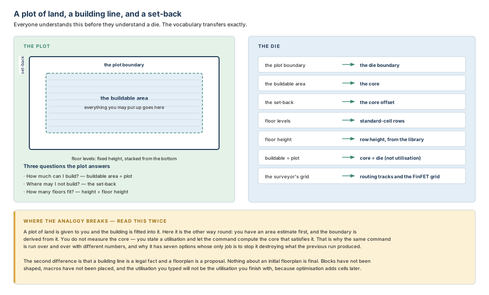
A plot is given to you and the building is fitted into it. Here the arithmetic runs the other way: the area estimate comes first, and the boundary is derived from it. You do not measure a core and then check the utilisation; you state a utilisation and let the command compute the core that satisfies it. That is why the same command is run over and over with different numbers, and why it carries seven options whose only purpose is to stop it destroying what the previous run produced.
The second difference matters more. A building line is a legal fact; an initial floorplan is a proposal. Blocks have not been shaped, macros have not been placed, and the utilisation you type will not be the utilisation you finish with, because optimisation, clock-tree synthesis and hold fixing all add cells after this command has run.
Now the engineering model
A floorplan describes four things: the size of the core; the shape and placement of standard-cell rows and routing channels; standard-cell placement constraints; and the placement of peripheral I/O, power, ground, corner and filler pad cells. That list is worth learning verbatim, because it is also the list of things that a floorplan does not describe — no block shapes, no macro locations, no pins, no power mesh. Those are later chapters, and each of them assumes this one is finished.
One command does the work: initialize_floorplan. It creates a floorplan with a boundary, a core, a site array or rows, and wire tracks. Before it runs, you must have opened a physical design or created one with a netlist reader. After it runs, you refine by running it again.
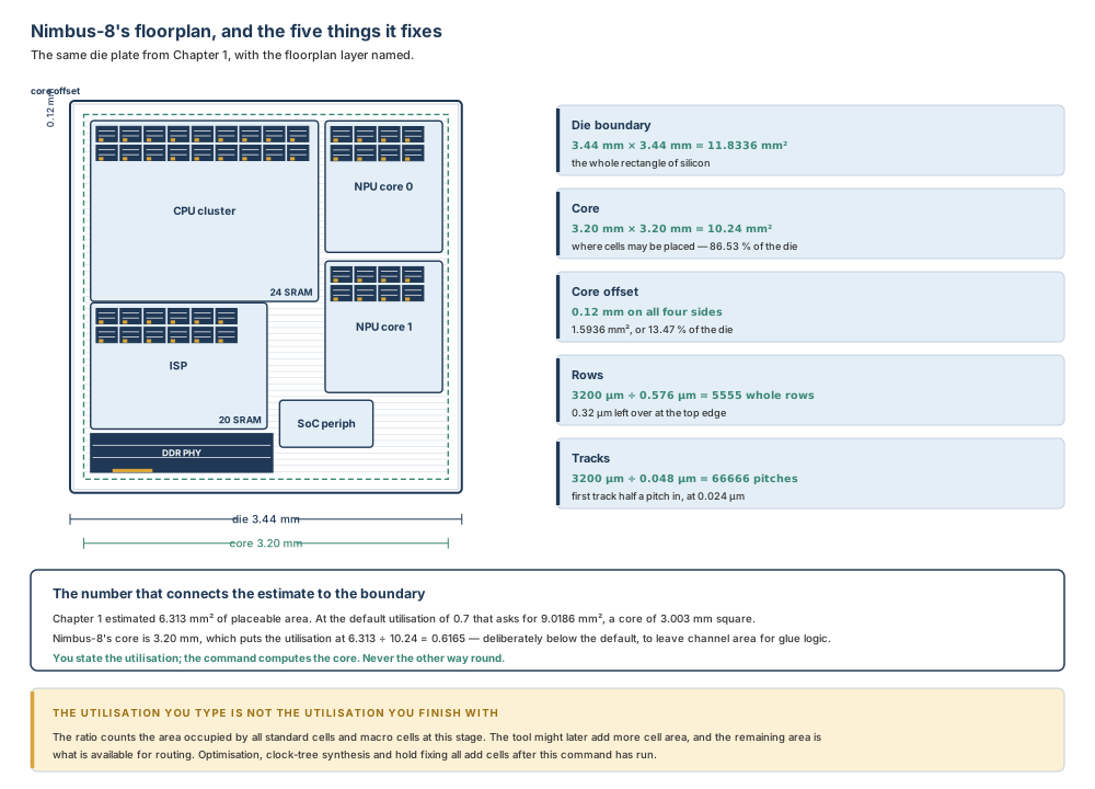
Figure 4.3 puts all of that on the design this book has been carrying since Chapter 1, with the numbers attached. Read it now for the anatomy — die, core, offset, rows, tracks — and read it again after §4.5, where the same numbers are derived rather than presented.
Do not confuse these
| This | Not this | How to tell them apart in one question |
|---|---|---|
| Die boundary | Core | May a standard cell be placed there? The core is where cells go; the die is the whole rectangle, and the strip between them is the core offset. |
| Core offset | Routing channel | Is it inside the core? The offset is outside it, between core and die. A channel is inside the core, between blocks or between rows. |
| The utilisation you type | The utilisation you finish with | Has optimisation run yet? The ratio describes the area occupied at this stage; the tool adds more cell area later. |
-side_ratio | -side_length | Did you give proportions or millimetres? Ratios are relative and mutually exclusive with lengths, which are absolute. |
-control_type core | -control_type die | Which boundary do your dimensions describe? With core the offsets are added to reach the die; with die they are subtracted to reach the core. |
| Row height | Track pitch | Which one is yours to choose? Neither. Both come from the technology data — and one is a whole multiple of the other. |
| Outline view | Design view | Are there leaf cells in it? An outline holds hierarchy but no leaf cells and no nets; a design view holds everything. |
write_floorplan | write_def | Does the output carry design intent? The DEF carries layout, connectivity and constraints; the floorplan writer adds the intent a DEF cannot express. |
4.2 The concepts, built in dependency order
4.2.1 Three floorplan styles, and what each one costs
Chapter 1 named the three styles. Here they are, properly, because the choice changes what the rest of the chapter has to produce.
Channelled floorplans contain spacing between blocks for the placement of top-level macro cells. The spacing lets the tool place standard cells between blocks. That is the whole idea: a channelled floorplan reserves core area so that top-level logic has somewhere to live.
Abutted floorplans have blocks touching, and the tool does not allocate space for macro cell placement between them. Designs with abutted floorplans do not require top-level optimisation, because all the logic is pushed down into the blocks. The costs are real and they are all downstream: abutted floorplans might require over-the-block routing to meet design requirements; the style requires more attention to clock planning and to feedthrough management; and routing congestion might become an issue. Because of those difficulties, the narrow-channel style is often used instead, to minimise the spacing between blocks rather than eliminate it.
Narrow-channel floorplans provide a balance. You abut certain blocks where top-level cells are not needed, and elsewhere reserve a channel between certain blocks for top-level clock routing or other special-purpose cells.
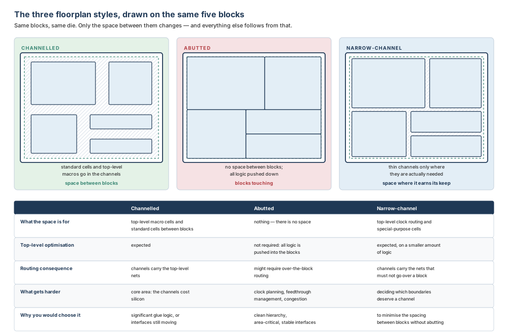
Why does the style belong in this chapter rather than the block-shaping chapter? Because the style decides the core area, and the core area is what this command creates. An abutted floorplan needs a core barely larger than the sum of the blocks; a channelled one needs the blocks plus the channels. Choose the style after you know the area and before you fix the boundary, and the utilisation you type follows from the choice. Choose it afterwards and you will be re-running this command with a different number, which is legal but wasteful.
4.2.2 The library, and why floorplanning starts with an outline
Before a netlist can be read, there has to be somewhere to put it. create_lib creates the design library that will contain the design, with -technology naming the technology file and -ref_libs the reference libraries. If the library already exists, open_lib opens it.
icc2_shell> set libs [glob -directory ${lib_dir} *.ndm]
icc2_shell> create_lib -technology nimbus8.tf -ref_libs $libs \
   nimbus8.dlib
Then the netlist. Chapter 3 required read_verilog, the flat netlist reader, and explicitly forbade the outline reader. This chapter reverses that: to read the Verilog netlist and begin floorplanning, use read_verilog_outline.
icc2_shell> read_verilog_outline -top NIMBUS8 nimbus8.v
The outline reader exists because it processes very large designs efficiently. To conserve resources and minimise turnaround time it creates an outline view of the blocks at the different levels of design hierarchy: the outline design contains hierarchy, but no leaf cells and no nets.
Two consequences follow immediately. First, the outline reader does not partition the design. To partition it you commit the design blocks with commit_block and expand the blocks to their full netlist representations with expand_outline. Second, during early floorplanning you can reduce the tool's disk and memory requirements by saving only hard macros, interface logic, standard-cell area and standard-cell count information. That reduced set is stored in the outline view, and it is sufficient for refining block shapes before floorplan-level placement and pin assignment.
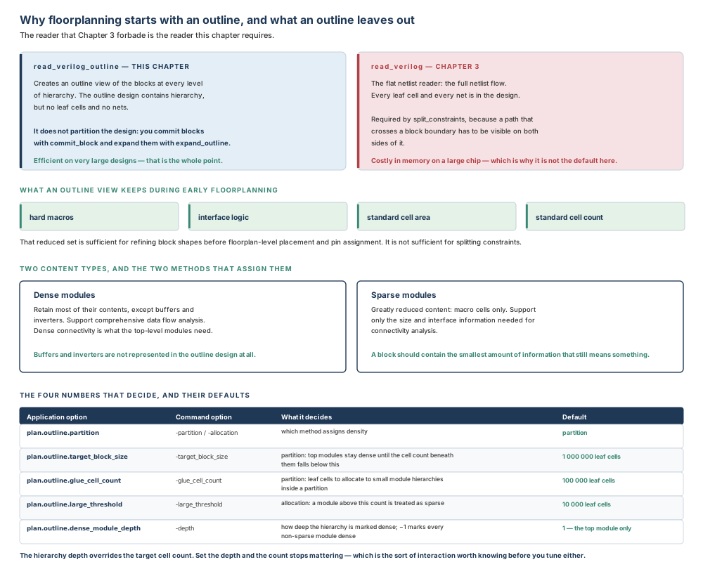
The two readers are wrong in opposite chapters, and the mistake is symmetrical. Use the outline reader in Chapter 3 and the split has nothing to cut, because the paths that cross block boundaries are not in the design. Use the flat reader here and you have spent the memory of a full-chip netlist to produce a boundary that needed hierarchy and areas only. Both are legal commands that run without complaint. The check is current_design, which reports the representation.
4.2.3 Dense and sparse modules, and the two methods that assign them
On a very large design, blocks should contain the smallest amount of information necessary to perform a meaningful analysis. To support that, the tool separates Verilog modules into two content types. Dense modules retain most of their contents, except buffers and inverters, and support comprehensive data flow analysis. Sparse modules have greatly reduced content, contain only macro cells, and support only the size and interface information needed for connectivity analysis.
Which modules are marked which is decided by one of two methods, chosen with -partition or -allocation on the reader, or by the plan.outline.partition application option. By default, the partition method is used.
In the partition method the tool examines the modules in the hierarchy and determines module density from the target block size and the number of leaf cells in the block. Top-level modules are marked dense until the hierarchical cell count beneath the module is less than a target block size — and buffers and inverters are included in that hierarchical cell count. This keeps connectivity in the top levels of hierarchy, which is where data flow analysis needs it. The target block size is plan.outline.target_block_size, by default 1 000 000 leaf cells, overridable with -target_block_size. After the partitions are designated, small module hierarchies within each partition are also designated dense, to maintain connectivity for data flow analysis; the target number of leaf cells to allocate to those is plan.outline.glue_cell_count, by default 100 000, and a value of −1 avoids marking any of the small modules dense. Buffers and inverters are not represented in the outline design and are not included in that glue cell count.
In the allocation method the tool explores as much of the design hierarchy as possible within a memory budget expressed as a maximum number of leaf cell instances. Modules that exceed a leaf cell count threshold are considered large and are treated as sparse in the outline view; buffers and inverters are again not counted. That threshold is plan.outline.large_threshold, by default 10 000 leaf cells.
Cutting across both methods is the depth control. plan.outline.dense_module_depth specifies the module hierarchy depth that should be marked dense; by default the depth is one and only the top-level module is marked dense. -depth overrides it, and a value of −1 marks all non-sparse modules dense. The hierarchy depth overrides the target cell count.
Two things in that section are easy to misread and worth stating flatly. Buffers and inverters count in the partition method's hierarchical cell count but do not count in the glue cell count or the allocation threshold — because they are not represented in the outline design at all. And the depth overrides the cell count, so tuning both at once means only one of them is doing anything. Set the depth first, decide whether you still have a problem, and only then touch the counts.
…you set the depth to −1 on a large chip? Every non-sparse module becomes dense, which is the most information the outline can hold, and the memory saving the outline reader exists to deliver largely disappears. That is occasionally the right answer — a data flow analysis that has to see deep into the hierarchy — but it should be a decision, not a default that someone copied from a smaller project's script.
4.2.4 Five ways to say how big
After the netlist is read, initialize_floorplan defines a floorplan boundary based on your design criteria. You can create a floorplan by specifying the length ratio between the floorplan edges, the length of the core or die edges, the aspect ratio, or the exact width and height. The step uses the outline view for the top-level design.
The five levers, and what each one settles:
| Option | What you are stating | Default if you do not state it |
|---|---|---|
| -core_utilization ratio | The fraction of the core occupied by all standard cells and macro cells, between 0 and 1 | 0.7 |
| -side_ratio {…} | The relative proportion of each floorplan edge to the sum of all the values listed | none; mutually exclusive with -side_length |
| -side_length {…} | The absolute length of each edge. A rectangle has only two: width and height | none; mutually exclusive with -side_ratio |
| -boundary {{x y} …} | Explicit coordinates, for any rectilinear shape | none |
| -core_offset {…} | The distance between the side of the core and the side of the die boundary | the minimum I/O cell height; 0 if there are no I/O cells |
Two more options decide what those numbers are measured against. -control_type takes core or die, and core is the default: the dimensions apply to the core boundary and the core offsets are added to reach the die boundary. With die, the dimensions apply to the die boundary and the offsets are subtracted to reach the core. And -macro_utilization specifies the utilisation of the macro cells; its default is the same as the core utilisation value.
-core_offset deserves a sentence of its own because its argument shape changes meaning. One value is used for all sides. Two values give the horizontal distance from the die boundary's vertical edges and the vertical distance from its horizontal edges. More than two are side numbers based on the standard rectilinear numbering — and, importantly, those side numbers do not correlate with the side_a, side_b naming used to size each edge.
# One value: the same offset on every side.
icc2_shell> initialize_floorplan -core_offset 100

# Two values: 50 horizontally, 100 vertically.
icc2_shell> initialize_floorplan -core_utilization 0.8 \
   -core_offset {50 100}
…you specify -core_utilization and nothing else? The command computes a core large enough that the placeable area occupies that fraction of it, gives the core the default rectangular shape, and offsets the die from it by the minimum I/O cell height. That is a complete, legal floorplan from one option — and it is exactly how a first exploratory run should look, because there is no point specifying edges before you know roughly how big the thing is.
4.2.5 Shapes, and how many numbers each one needs
-shape takes R, L, T or U, and R — rectangular — is the default. The shape decides how many values the sizing option must carry: a rectangle has only two dimensions, width and height, while the L, T and U shapes need four, six and six respectively. If you provide more values than the shape requires, the extra values are ignored; if you provide fewer, the tool issues an error message.
The arithmetic of a ratio is worth doing once by hand. Each value is the proportion of that edge to the sum of all the values listed. So for an L-shaped block given -side_ratio {1 2 1 1}, the sum is 5, each side given as 1 is one fifth — 20 percent — of the sum, and the side given as 2 is two fifths, or 40 percent.
A rectangle takes only two values, and the order is the one place people slip. -side_ratio {3.0 1.0} is three wide by one high — an aspect ratio of 3.0 — and -side_ratio {1.0 3.0} is the same rectangle stood on end, an aspect ratio of 0.33. Both cores have the same area, because the ratio changes the shape and never the size; the size still comes from the utilisation and the area it has to hold.
-orientation takes N, W, S or E and repositions the block by rotating it clockwise; for a rectangle the orientation is always N. And -coincident_boundary, which defaults to true, decides whether the die boundary follows the shape of the core. If it is true, the die assumes the same shape as the core and requires a -core_offset with the same number of sides as the core. If it is false, the die boundary is rectangular and the offset requires only four values; the die is then created so that each offset value is honoured to the closest core edge, and its bounding box is the minimum size that meets all four.
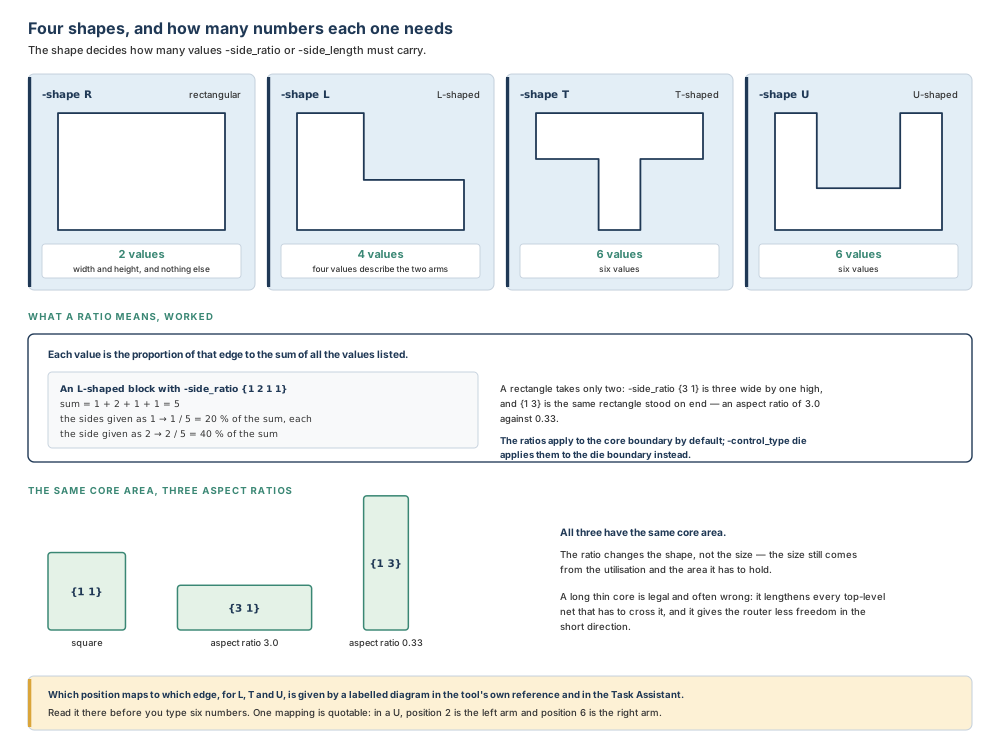
For a complex shape that none of the four templates describes, -boundary takes explicit coordinates and builds whatever rectilinear outline you list, with -control_type deciding whether those coordinates are the die's or the core's. An H-shaped floorplan is twelve coordinate pairs and one command. Reach for it when the shape is dictated by something outside the design — a package, a neighbouring die, an existing pad ring — and not before, because a rectangle you can defend beats a rectilinear shape you cannot.
4.2.6 Rows: how many, which way up, and how much room between
Three separate decisions hide behind the word "rows", and they are easy to merge on first meeting.
How many is arithmetic, not an option. The core side divided by the row height gives the number of whole rows, and whatever is left over is a remainder at the edge. For Nimbus-8's 3.20 mm core and the teaching library's 0.576 µm row height, 3200 ÷ 0.576 = 5555.56, so there are 5555 whole rows and 0.32 µm left over. The remainder is not a defect.
Which way up is -flip_first_row, which defaults to true. It specifies whether the command flips the first row at the bottom of the core area for horizontally placed cell rows, or the leftmost row for vertically placed ones. To avoid flipping the first row, say -flip_first_row false.
How much room between is -row_core_ratio, a number between 0 and 1.0 that specifies the amount of channel area between cell rows in the core area to reserve for routing. A smaller ratio creates more space for routing channels; a value of 1.0 creates none. The default is 1.0 — and the ratio should be equal to or greater than the core utilisation value.
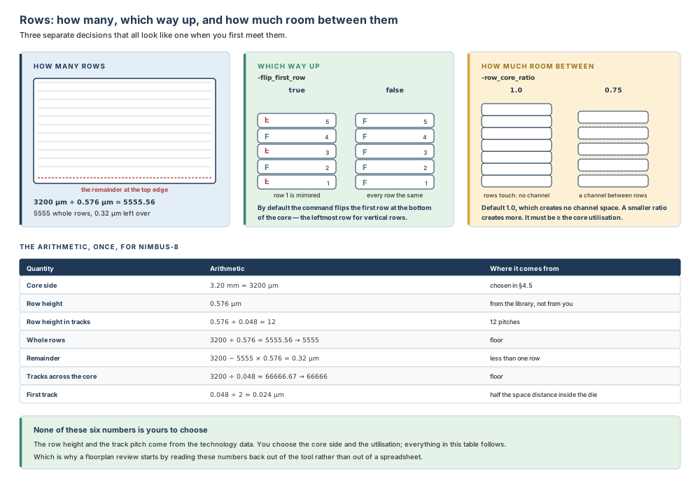
-row_core_ratio should be equal to or greater than the core utilisation. Set a utilisation of 0.8 and a row-to-core ratio of 0.7 and you have asked for a core in which 80 percent is occupied by cells while only 70 percent of it carries rows — which cannot be satisfied. The two numbers look independent because they are separate options with separate defaults, and they are not.
4.2.7 Tracks
initialize_floorplan creates wire tracks along with the boundary, the core and the rows. The other track commands exist to change or add to what it produced.
To create routing tracks, use create_track, specifying the layer with -layer, the number of tracks with -count, the pitch distance between tracks with -space, the wire width with -width and so on. The location can be given two ways. -coord specifies the location of the first track, with the tool using the x- and y-coordinates set by -dir, which specifies the stepping direction in which the tracks are placed; by default, the first track is located at half the space distance inside the die area. Alternatively -relative_to aligns one of the track lines to the lower boundary of either the core area bounding box or the block bounding box, and the tracks are then created completely within the block boundary even if that boundary is larger than the core; -end_grid_relative_to does the same for subsequent grid points.
icc2_shell> remove_tracks -all
1
icc2_shell> create_track -layer METAL3 -space 0.5
{TRACK_0}
icc2_shell> report_tracks
Layer          Direction     Start         Tracks    Pitch          Attr
------------------------------------------------------------------------
METAL3             Y         0.250          4023     0.500       default
That report is the whole reason to run it. The pitch is 0.500 and the start is 0.250 — half the pitch, exactly as documented — so one line of output confirms both the number you typed and the rule the tool applied to it.
There is an easier method. If you have defined an appropriate track constraint, derive_tracks creates tracks automatically; -layers and -labels specify the layer and the label, and if no label is specified the command searches all default label track constraints in all the given layers. -verbose reports the details of track generation on the specified layers.
# Let the constraints decide, on two layers.
icc2_shell> derive_tracks -layers {M1 M2}
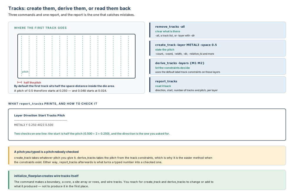
report_tracks prints it back with its start. Half the pitch is where the first track goes, so the report contains its own consistency check.4.2.8 The FinFET grid, and the rows and grids you did not create
The tool supports a FinFET grid to guide the placement of library cells that contain FinFET devices. The x- and y-spacing and offset values for that grid are specified in the technology file — not by you. report_grids -type finfet reads them out, and check_finfet_grid checks for placement or boundary violations with respect to the grid, with -objects narrowing the check to specific object types.
Sixteen commands are FinFET-grid aware, initialize_floorplan among them, and so are the block-shaping, macro-array, I/O-ring, placement and site-row commands that later chapters use. That is the reason to run the check here rather than later: a boundary point that is off-grid at floorplan time is off-grid for everything built on it.
One more thing the command creates without being asked. By default initialize_floorplan creates site array objects; -use_site_row forces it to create site rows instead. -site_def names the site definition to use when the technology file has more than one; the default is to use the default site def, and if there is no default, the command uses the site def with the smallest site width.
4.2.9 Re-running the command without losing your work
After creating the initial floorplan, you repeat the command with different options to experiment with different shapes and characteristics. That is the intended workflow, and it has one sharp edge: by default the command deletes all existing routes and rebuilds everything from the options you have given it this time.
Seven options stop it. -keep_boundary uses the existing die boundary, and issues an error if the core-based constraints result in a core too large to fit inside it. -keep_pg_route keeps the power and ground routes; -keep_detail_route keeps all the routes except those. -keep_placement takes a list of object types — io, macro, block, std_cell, physical_only or all. -keep_objects takes named cells and nets, either as a collection from an object-access command or as name patterns in a Tcl list. -keep_object_types takes placement_blockage, routing_blockage and move_bound. And -keep_all keeps macros, standard cells, I/O, physical-only objects, blocks, blockages, detail routes and PG routes.
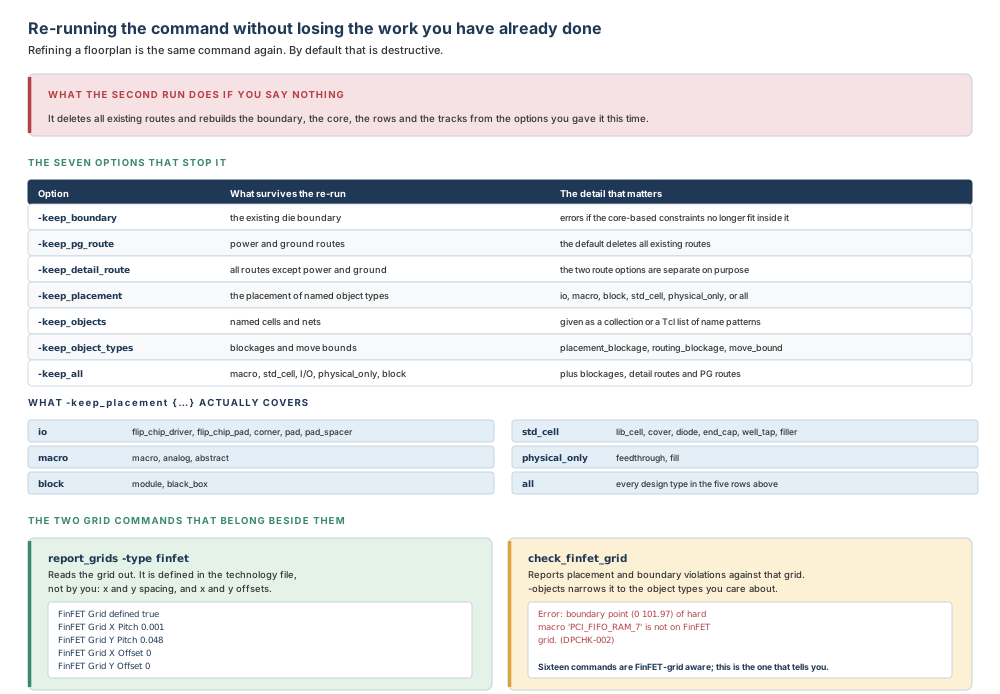
-keep_placement actually covers, which is more than its name suggests.4.3 Inputs, outputs and readiness
What has to be true before the first run
| Input | Why the command needs it | Consequence if it is missing or wrong |
|---|---|---|
| A design library with a technology file and reference libraries | The row height, the site definitions, the track pitches and the FinFET grid all come from the technology data | Nothing can be created, because the command has no unit of row to work in. |
| An open physical design, or a design created by a netlist reader | The command needs something to compute an area for | The command has nothing to size; open a block or read a netlist first. |
| An area estimate you can defend | The utilisation is a ratio, and a ratio needs a numerator | A boundary that looks legal and is the wrong size — the most expensive kind of mistake in this chapter. |
| A decision about the floorplan style | Channels are core area, and core area is what the command creates | A utilisation typed for the wrong style, and a second run to correct it. |
What the floorplan makes, and what it does not
Created by initialize_floorplan | Not created; belongs to a later chapter |
|---|---|
| A die boundary | Block shapes |
| A core | Macro placement |
A site array, or site rows with -use_site_row | Power and ground mesh |
| Wire tracks | Pin assignment on block boundaries |
| Standard-cell placement constraints | Timing budgets, which need constraints applied first |
| The positions available for peripheral I/O, power, ground, corner and filler pad cells | The pad cells themselves, and the I/O rings that guide them |
Reporting what you have
report_design -floorplan, or report_design -all, reports the floorplan information. What it covers is worth knowing before you need it: the core and chip area; the site rows, with name, width, height, number of rows, number of tiles and area for each; the blockages, with a count and an area for each blockage type; the power domains, with the domain name, voltage area name and primary power and ground nets; the voltage areas, with name, number of shapes, area, target utilisation and bounding box; the group bounds and move bounds; the route guides; the multibit registers; the reserved placement groups; and the layers, with name, direction, pitch, default width, minimum width, minimum spacing, and minimum spacing between the same nets.
That is a lot for one command, and the reason to run it here is narrow: it is where the core and chip area, the site-row count and the layer pitches can be read in one place, without a timing update and without a spreadsheet.
Preflight checklist
- The library exists, and
create_libwas given the technology file and the reference libraries — oropen_libopened one that already had them. - The netlist was read with the outline reader, and
current_designconfirms an outline representation. - You know the placeable area you are sizing for, and where that number came from.
- The floorplan style is decided, and the utilisation you are about to type reflects it.
- You know whether your dimensions describe the core or the die, and
-control_typesays so explicitly rather than relying on the default. - If the shape is not rectangular, you have read the edge-labelling reference and counted your values.
-row_core_ratio, if you set it, is at least as large as the core utilisation.- If this is not the first run, you have decided which
-keep_*options belong on the command line. - The unit report from Chapter 2 has been printed once, so the log records what "100" meant in this session.
When the result is not trustworthy
| Condition | What it looks like | Why it matters |
|---|---|---|
| The utilisation was chosen for the area estimate and not for the style | A clean, legal boundary at the number you typed | A channelled floorplan needs blocks plus channels. Size for the blocks alone and the channels come out of somebody's block. |
| The rows and tracks were never read back | A floorplan report nobody ran | Row height and track pitch come from the technology data. If your spreadsheet disagrees with the tool, the tool is right. |
A re-run was launched without -keep_* | A floorplan that looks like the previous one, minus the routes | The default deletes all existing routes. The loss is silent, because deleting a route is not an error. |
| The FinFET grid was never checked | No errors, because nothing asked | Sixteen commands are grid-aware. An off-grid boundary point at floorplan time is off-grid for every one of them. |
The readiness gates that belong to this chapter
dp_pre_floorplan is the gate for this chapter, and its three checks are all about the technology data rather than your design: it checks that the technology file information is correct, that the layer directions are set, and that the design contains both horizontal and vertical layers.
dp_floorplan_rules is the gate on the other side. It checks the segment parity rule and the macro spacing rule, and it runs the checks performed by check_finfet_grid.
# Before the floorplan: is the technology data fit to floorplan with?
icc2_shell> check_design -checks {dp_pre_floorplan}

# After it: does the geometry obey the rules?
icc2_shell> check_design -checks {dp_floorplan_rules}
Why does the pre-floorplan gate check the technology file rather than the design? Because at this point in the flow there is almost no design to check — an outline view with areas and hierarchy. What can be wrong is the data the command will derive everything from. A missing layer direction or a technology file with no vertical layers produces a floorplan that is geometrically fine and physically unroutable, and the gate exists to find that in a second rather than in a week.
4.4 The guided workflow
4.4.1 A session from an empty directory to a written floorplan
- Start design planning mode from the project directory, and print the units and the non-default application options.
- Create the design library with its technology file and reference libraries, or open the one that exists.
- Run the pre-floorplan gate, before there is anything to lose.
- Read the Verilog netlist with the outline reader, naming the top module.
- Confirm the representation with
current_design. - Run
initialize_floorplanwith a size, a shape and an offset. - Read the result back:
report_design -floorplan, thenreport_tracks, thenreport_grids -type finfet. - Check the geometry:
check_finfet_grid, then the floorplan-rules gate. - Refine by re-running step 6 with different numbers and the right
-keep_*options. - Write it out with
write_floorplan, and save the library.
4.4.2 Command by command
create_lib — somewhere to put the design
Purpose. Create the design library that will contain the design, bound to a technology and a set of reference libraries.
Syntax in plain English. The library name is positional. -technology takes the path to a technology file, or -use_technology_lib names a library to take the technology from instead. -ref_libs takes the reference libraries. -scale_factor sets the library's database units per micron — the number Chapter 2 spent a section on, and the one you cannot change afterwards. -convert_sites, -base_lib and -dont_set_current cover the rest.
icc2_shell> set libs [glob -directory ${lib_dir} *.ndm]
icc2_shell> create_lib -technology nimbus8.tf -ref_libs $libs \
   nimbus8.dlib
Expected result. A library exists and is current.
Verification. report_design -library. And, because Chapter 2 earned the right to say so: get_attribute [get_lib nimbus8.dlib] scale_factor before you rely on any coordinate.
Common mistakes. Creating a library without the technology file and discovering it when the floorplan has no rows. Choosing a scale factor on the first day of a project without checking the technology file's own length precision.
Prerequisites. A technology file and reference libraries on the search path.
Finding the rest. man create_lib, and man open_lib for the case where the library already exists.
read_verilog_outline — the netlist, cheaply
Purpose. Read the Verilog netlist and create an outline view of the blocks at the different levels of hierarchy, so that floorplanning can begin without the memory cost of the full netlist.
Syntax in plain English. The file names are positional and -top names the top module. -library and -design name the library and design. -partition and -allocation choose the density method; -target_block_size, -glue_cell_count, -large_threshold, -target_cell_count and -depth tune it. -dense_modules, -sparse_modules and -port_modules name modules explicitly. -leaf_cells, -buffer_cells and -macro_cells tell the reader which cells are which.
icc2_shell> read_verilog_outline -top NIMBUS8 nimbus8.v
Expected result. An outline design containing hierarchy, and no leaf cells or nets.
Verification. current_design names the representation. On a large design, also check that the density assignment is what you intended before you spend an hour on it.
Common mistakes. Expecting the design to be partitioned — it is not; commit_block and expand_outline do that. Tuning the cell counts while the depth is also set, so that only the depth is having an effect.
Prerequisites. A library, and the netlist file on the search path.
Finding the rest. man read_verilog_outline, and man read_verilog for the full netlist flow Chapter 3 needed.
initialize_floorplan — the command this chapter is about
Purpose. Create an initial floorplan with a die boundary, a core, a site array or rows, and wire tracks — either with a die boundary coincident with the core, or a rectilinear core inside a rectangular die.
Syntax in plain English. Everything is optional, and the options fall into four groups: what shape, how big, where the die sits relative to the core, and what to keep from last time.
| Option | What it decides | Default if you say nothing |
|---|---|---|
| -shape R | L | T | U | The core shape, or the die shape if the control type is die | R, rectangular |
| -orientation N | W | S | E | Which way the rectilinear shape faces; rotated clockwise | for -shape R the orientation is always N |
| -control_type core | die | Whether your lengths and ratios describe the core or the die | core, so offsets are added to reach the die |
| -side_length {…} | Absolute edge lengths | none; two values for R, more for L, T and U |
| -side_ratio {…} | Relative edge proportions | none; mutually exclusive with -side_length |
| -core_utilization ratio | The fraction of the core occupied by standard cells and macros | 0.7 |
| -macro_utilization ratio | The utilisation of the macro cells | the same as the core utilisation value |
| -boundary {{x y} …} | An explicit rectilinear outline | none |
| -core_offset {…} | The distance from core edge to die edge | the minimum I/O cell height; 0 with no I/O cells |
| -coincident_boundary true | false | Whether the die follows the shape of the core | true |
| -row_core_ratio ratio | Channel area between cell rows reserved for routing | 1.0, which creates no channel space |
| -flip_first_row true | false | Whether the first row is flipped | true |
| -honor_pad_limit | Adjusts core and die to honour a pad-limited design | not specified, so the core is built from the utilisation; rectangular shapes only |
| -site_def name | Which site definition to use | the default site def; failing that, the one with the smallest site width |
| -use_site_row | Create site rows instead of a site array | a site array |
| -origin_offset {x y} | Where the die bounding box's lower-left corner sits relative to the block origin | the block origin |
| -row_pattern name | A row pattern from the physical rule section of the technology file | none |
| -keep_boundary | Use the existing die boundary | not specified; the boundary is rebuilt |
| -keep_pg_route | Keep the power and ground routes | all existing routes are deleted |
| -keep_detail_route | Keep every route except power and ground | all existing routes are deleted |
| -keep_placement {…} | Keep placement of io, macro, block, std_cell, physical_only or all | not specified; placement is rebuilt |
| -keep_objects list | Keep named cells and nets | not specified |
| -keep_object_types {…} | Keep placement blockages, routing blockages, move bounds | not specified |
| -keep_all | Keep macros, standard cells, I/O, physical-only, blocks, blockages and both kinds of route | not specified |
# A first exploratory run: one option, and the defaults do the rest.
icc2_shell> initialize_floorplan -core_utilization 0.8 \
   -core_offset {1000 1000 1000 1000}

# An L-shaped core, sized by proportion.
icc2_shell> initialize_floorplan -core_utilization 0.7 -shape L \
   -orientation N -side_ratio {1 1 1 1} -core_offset {100.0} \
   -flip_first_row true -coincident_boundary true

# A rectangle three times as wide as it is high.
icc2_shell> initialize_floorplan -core_utilization 0.7 -shape R \
   -orientation N -side_ratio {3.0 1.0} -core_offset {100.0} \
   -flip_first_row true -coincident_boundary true

# A complex rectilinear die, from coordinates.
icc2_shell> initialize_floorplan -control_type die -core_offset 100 \
   -boundary { {0 0} {0 3000} {1000 3000} {1000 2000} \
   {2000 2000} {2000 3000} {3000 3000} {3000 0} \
   {2000 0} {2000 1000} {1000 1000} {1000 0} }
Expected result. A boundary, a core, a site array or rows, and wire tracks.
Verification. Three reports and one check, in that order: report_design -floorplan for the areas and the site rows, report_tracks for the pitches and starts, report_grids -type finfet for the grid, and check_finfet_grid for violations against it.
Common mistakes. Relying on the default -control_type and being surprised that the offsets were added rather than subtracted. Typing -side_ratio {1 3} for a core meant to be wide. Setting -row_core_ratio below the utilisation. Re-running without -keep_* and losing the PG routing.
Prerequisites. An open physical design, or one created by read_verilog or read_verilog_outline.
Finding the rest. man initialize_floorplan — including the labelled diagram that maps argument positions to edges for the L, T and U shapes.
read_physical_rules — a floorplan from a rules file
Purpose. Load a physical rules file so that the floorplan is created from the specifications it lists rather than from options alone.
Syntax in plain English. The file name is positional; -include narrows what is read and -library names the library. The rules content can also live inside a technology file.
icc2_shell> read_physical_rules in.prf
icc2_shell> initialize_floorplan -row_pattern hybrid_a
Expected result. A floorplan built using the information in the rules file. In a physical rules file you can include placement rule constraints, physical cell and pin properties, and stream-in instructions in one unified format.
Verification. The rows and tracks the floorplan ends up with. For layers that have a track pattern defined in the file, wire tracks are created from that pattern; for layers without one, they are created the ordinary way.
Common mistakes. Two, both documented as conditions rather than errors. To make the tool use the rules file to calculate the core area you must set -row_pattern, and you must not set -boundary, -keep_boundary or -side_length. And where a hybrid design has site rows of different heights, the cells need balancing to arrive at an optimal core area — which is what the hybrid-design application option is for.
icc2_shell> set_app_options \
   -name plan.floorplan.enable_adjust_core_area_for_hybrid_design \
   -value balance
Prerequisites. A physical rules file, and hybrid rows defined in it if you intend to use a row pattern.
Finding the rest. man read_physical_rules.
modify_die_area — shrink or grow what you already have
Purpose. Shrink or expand the die area, or the size of the design, without rebuilding the floorplan from scratch.
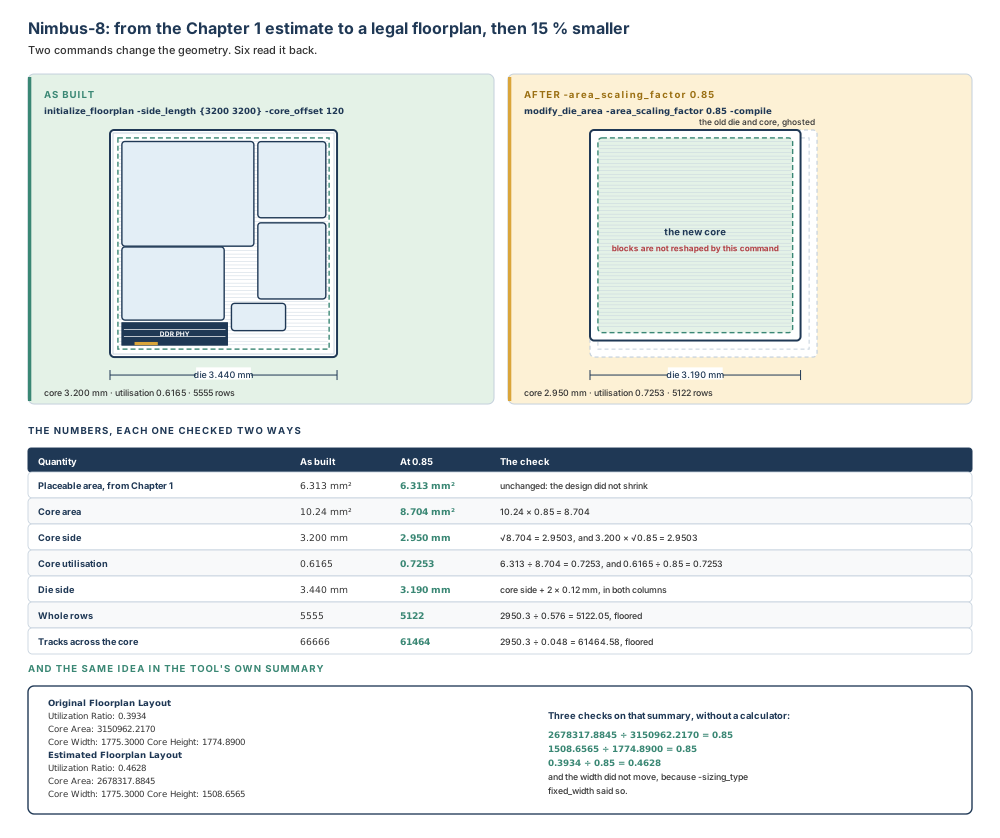
Syntax in plain English. The three scaling options — -area_scaling_factor, -height_scaling_factor and -width_scaling_factor — control the resizing of the core area, its height and its width, with valid values from 0.1 to 10. -core_utilization instead specifies the required utilisation of the core area. -fixed_edges lists the edges whose length must remain unchanged. -sizing_type defines constraints on aspect ratios, taking fixed_width, fixed_height or fixed_aspect_ratio. -row_pattern names the row pattern to use. -compile calculates and prints a summary of the estimated floorplan layout and creates a new floorplan based on the estimates. And -run_track_creation_script runs a custom script that re-creates the tracks after the resizing; by default the command derives the track information from the input floorplan and reuses it.
# Shrink the core area to 85 % of its original size.
icc2_shell> modify_die_area -area_scaling_factor 0.85

# Shrink the core height to 80 % — a 20 % reduction.
icc2_shell> modify_die_area -height_scaling_factor 0.8

# Or state the utilisation you want instead of a factor.
icc2_shell> modify_die_area -core_utilization 0.75

# Grow the core height to 110 % — a 10 % increase.
icc2_shell> modify_die_area -height_scaling_factor 1.1

# Shrink by area but hold the width, and print the summary first.
icc2_shell> modify_die_area -area_scaling_factor 0.85 \
   -sizing_type fixed_width -compile
Expected result. With -compile, a die-size exploration summary that prints the original and the estimated floorplan layout side by side — utilisation ratio, core area, core width, core height and boundary coordinates for each — and then a new floorplan based on the estimate.
Verification. Divide. The estimated core area over the original should be the factor you asked for, the dimension you fixed should be unchanged, and the utilisation should have moved by the reciprocal of the factor. §4.5 does this on real numbers.
Common mistakes. Aiming for a large change. Reducing the size can offer benefits — the smaller the die, the more dies per wafer — but you should aim for minor changes, because major ones can cause excessive utilisation or macros that no longer fit. The action counts as successful when the shrunken design is still routable, still meets its operating speed requirements, and still meets its allowable power consumption.
Prerequisites. An existing floorplan.
Finding the rest. man modify_die_area.
4.4.3 Getting the floorplan out, back in, and into another block
Three commands, and one of them reuses machinery from Chapter 3.
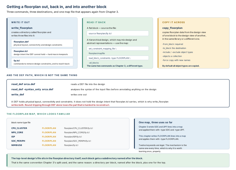
Writing. write_floorplan creates a directory named floorplan and writes three files into it. floorplan.def contains the physical layout, connectivity and design constraint information. floorplan.tcl contains additional design intent that cannot be described in the DEF file — hard macro keepout margins, for instance. fp.tcl contains commands to remove design constraints such as voltage areas, bounds and routing guides. The command supports both design views and abstract views for blocks, and it also writes out the constraint mapping file that maps each block to its corresponding fp.tcl.
Options control what goes in. -include and -exclude take object type lists — and there are thirty of them, from blockages and bounds through rows, tracks and vias to bump_regions and anchors; by default all supported object types are written out. -objects and -blocks narrow it further. -include_physical_status and -cell_types filter by status and by kind of cell. -exclude_user_attributes takes none, which writes all the user-defined attributes out, or all, which excludes them. -force overwrites, -def_version sets the DEF version, and -read_def_options adds options to the read_def call in the generated fp.tcl.
# Just the hard macros, with their origins and orientations.
icc2_shell> write_floorplan -output "macros" -objects [get_cells \
   -physical_context -filter is_hard_macro==true]

# The PG regions, overwriting the directory if it exists.
icc2_shell> write_floorplan -force -objects [get_pg_regions] \
   -output pg

# Pad and macro cells that are fixed or unplaced.
icc2_shell> write_floorplan -force -include cells \
   -include_physical_status {fixed unplaced} -cell_types {pad macro}

# Clock, power and ground nets only; signal nets excluded.
icc2_shell> write_floorplan -force -output nets \
   -net_types {clock power ground}
Reading it back. For a flat block, source the fp.tcl file. For a hierarchical design that might contain a mix of design and abstract block representations, use the two commands from Chapter 3 with a different keyword: set_constraint_mapping_file assigns the map, and load_block_constraints -type FLOORPLAN -all_blocks sources each fp.tcl named in it, re-creating the floorplan for each block.
icc2_shell> source floorplan/fp.tcl

# or, for a hierarchical design
icc2_shell> set_constraint_mapping_file floorplan/mapfile
icc2_shell> load_block_constraints -type FLOORPLAN -all_blocks
The DEF path is adjacent and not the same. read_def reads a DEF file; -syntax_only analyses the syntax of the input files before annotating the objects on the design. write_def writes one out. What a DEF cannot carry is the design intent that floorplan.tcl holds, which is exactly why the floorplan writer produces both.
Copying. copy_floorplan copies floorplan data from the design view of a source block to the design view of an existing destination block; the designs can be in the same library or in different ones, and a design label can be given along with the block name. -from_block is required, -to_block names the destination, and -include, -exclude and -objects narrow what travels; by default all object types are copied. -force copies objects into an existing floorplan under new names even when they are already present.
# Everything, into the currently open block.
icc2_shell> copy_floorplan -from_block test:mem/placed

# Everything, into a named destination.
icc2_shell> copy_floorplan -from_block test:mem/placed \
   -to_block test:mem_copy/placed

# Only blockages and bounds.
icc2_shell> copy_floorplan -verbose -from_block test:mem/placed \
   -to_block test:mem_copy/placed -include {blockages bounds}
4.4.4 Floorplan rules for advanced technology nodes
Floorplans developed for advanced technology nodes have additional requirements for the placement and spacing of standard cells, macros and other objects. Seven commands create those rules, and one checks them.
| Command | What it defines | Example |
|---|---|---|
| set_floorplan_area_rules | A minimum area, maximum area, list of valid or invalid areas, or a range of them | a minimum standard-cell area of 100 |
| set_floorplan_enclosure_rules | Legal spacing between an enclosed object and its enclosing object | a routing blockage must enclose a cell on all sides with 5.0 of spacing |
| set_floorplan_halo_rules | Legal spacing between an enclosed object and its enclosing objects | a routing blockage must enclose a macro on all sides with 3.0 of spacing, outer type |
| set_floorplan_spacing_rules | Legal spacing between objects | a vertical step of 2.0 with an offset of 13.0 between named cells and the standard-cell area |
| set_floorplan_width_rules | Legal widths | the horizontal width of the standard-cell area must be an even multiple of 8.0 plus an offset of 40.0 |
| set_floorplan_density_rules | Floorplan density, such as the maximum bump density of the die | a local-window method with a window of {1 2}, a step of {3 4} and a maximum of 10 |
| set_floorplan_area_weight_rules | Floorplan area density with different object weights | weights of 1 and −1 for shapes on two metal layers, against an existing density rule |
# A minimum area for the standard-cell area.
icc2_shell> set_floorplan_area_rules -name area_rule_1 \
   -object_types std_cell_area -min 100

# A width that must fall on an 8.0 step with a 40.0 offset.
icc2_shell> set_floorplan_width_rules -name width_rule_1 \
   -object_types std_cell_area -type simple -direction horizontal \
   -step 8.0 -offset 40.0

# And then check the floorplan against the rules you created.
icc2_shell> check_floorplan_rules {floorplan_rule_1 floorplan_rule_2}
icc2_shell> check_floorplan_rules -object_types {std_cell hard_macro}
icc2_shell> check_floorplan_rules -lib_cells MACRO4
check_floorplan_rules takes the rules to check as a list after the command name, and with no arguments lists the currently specified floorplan rules. -object_types narrows the check to hard_macro, std_cell_area, soft_macro, block_boundary or core_area; -lib_cells narrows it to named library cells; -exclude_rules and -exclude_lib_cells take things out; -bbox restricts it to a region; and -error_view names a view for the violations.
One ordering constraint is documented and easy to trip over: create the floorplan density rule before you create a floorplan area weight rule, because the weight rule refers to the density rule by name. Everything else in this group can be created in any order, and all of it is checked by one command.
4.5 Worked example: Nimbus-8's floorplan, twice
The situation
Chapter 1 left Nimbus-8 with an area estimate and a partition, and nothing geometric. The estimate is 6.313 mm² of placeable area: 3.465 mm² of standard cells, 2.304 mm² of SRAM macros and the 0.544 mm² DDR PHY. The partition is four block references and one top-level hard macro, and the style is narrow-channel — thin channels between most blocks, with room for glue logic where the top level needs it.
Two questions have to be answered before anything is typed. How big should the core be? And how far should the die sit outside it?
Step 1 — Do the arithmetic before you open the tool
The default utilisation is 0.7. At 0.7, the estimate asks for a core of 6.313 ÷ 0.7 = 9.0186 mm², which is a square 3.0031 mm on a side. That is the floorplan the command would produce if you gave it nothing but the netlist.
Nimbus-8 does not take it. The narrow-channel style needs channel area that the estimate does not include, so the core is set to 3.20 mm square — 10.24 mm² — which puts the utilisation at 6.313 ÷ 10.24 = 0.6165. That is deliberately below the default, and the difference, 10.24 − 9.0186 = 1.2214 mm², is the channel budget: leftover core after packing placeable area at utilisation 0.70. That is not Chapter 1’s leftover between committed block shapes (10.24 − 8.149 = 2.091 mm²). Same word “channel,” two identities.
#=============================================================
# The arithmetic, written down before the command that uses it
#=============================================================
placeable area                              =  6.313 mm2
core at the default utilisation  6.313 / 0.70  =  9.0186 mm2
                                 sqrt(9.0186)  =  3.0031 mm

chosen core                        3.20 x 3.20  =  10.24 mm2
utilisation that implies          6.313 / 10.24  =  0.6165
channel budget                   10.24 - 9.0186  =  1.2214 mm2

core offset                                     =  0.12 mm per side
die                            3.20 + 2 x 0.12  =  3.44 mm
die area                           3.44 x 3.44  =  11.8336 mm2
core as a share of the die       10.24 / 11.8336  =  86.53 %
Step 2 — Start the session, and gate before you build
% icc2_shell -dp_mode

icc2_shell> report_user_units
... time 1.00ps, the project convention from the setup file ...

icc2_shell> report_app_options -non_default
... one line: lib.setting.use_tech_scale_factor is true ...

icc2_shell> set libs [glob -directory ${lib_dir} *.ndm]
icc2_shell> create_lib -technology nimbus8.tf -ref_libs $libs \
   nimbus8.dlib

icc2_shell> check_design -checks {dp_pre_floorplan}
... technology file correct; layer directions set; both
    horizontal and vertical layers present ...
The gate runs before the netlist, deliberately. It checks the technology data, and the technology data is what everything else will be derived from.
Step 3 — Read the netlist, cheaply, and prove which reader ran
icc2_shell> read_verilog_outline -top NIMBUS8 nimbus8.v
icc2_shell> current_design
{nimbus8:NIMBUS8.outline}
The representation is outline, which is what this chapter wants and what Chapter 3 forbade. If it had read design, somebody had used the flat reader and the session is carrying a full-chip netlist it does not need.
Step 4 — Create the floorplan
#=============================================================
# ./scripts/20_floorplan.tcl
#=============================================================

# Say what the numbers describe, rather than relying on the
# default: these are core dimensions, in microns.
initialize_floorplan -control_type core -shape R \
   -side_length {3200 3200} \
   -core_offset {120} \
   -coincident_boundary true \
   -flip_first_row true

# Read it back, three ways, before believing any of it.
report_design -floorplan
report_tracks
report_grids -type finfet
-control_type core is the default, and it is written out anyway. The reason is not caution about this run; it is the next engineer, who will read the script and have to decide whether 3200 is a core dimension or a die dimension. One redundant option removes a question. The same argument applies to -coincident_boundary and -flip_first_row: both are set to their defaults here, and both are now facts on the record rather than assumptions.
Step 5 — Check the six numbers you did not choose
| Quantity | Value | How it is obtained, and its check |
|---|---|---|
| Core side | 3.200 mm | chosen; 3200 µm as typed |
| Die side | 3.440 mm | 3.200 + 2 × 0.120 |
| Core area | 10.24 mm² | 3.20 × 3.20 |
| Die area | 11.8336 mm² | 3.44 × 3.44 |
| Offset area | 1.5936 mm² | 11.8336 − 10.24, which is 13.47 % of the die |
| Core utilisation | 0.6165 | 6.313 ÷ 10.24 |
| Row height | 0.576 µm | from the technology data — read, not chosen |
| Row height in tracks | 12 | 0.576 ÷ 0.048 |
| Whole rows | 5555 | 3200 ÷ 0.576 = 5555.56, floored |
| Remainder at the edge | 0.32 µm | 3200 − 5555 × 0.576 |
| Track pitch | 0.048 µm | from the technology data |
| Tracks across the core | 66666 | 3200 ÷ 0.048 = 66666.67, floored |
| First track | 0.024 µm | 0.048 ÷ 2 — half the space distance inside the die |
Six of those thirteen rows are yours: the core side, the offset, and the four areas and ratios that follow from them. The other seven come from the technology data, and the only correct way to obtain them is to read them out of the tool.
Step 6 — Somebody asks for it 15 percent smaller
Two weeks later the die cost target moves and the request is for 15 percent less core area. This is exactly what modify_die_area is for, and exactly the situation in which to print the summary before committing to it.
icc2_shell> modify_die_area -area_scaling_factor 0.85 -compile

Die Size Exploration Summary
--------------------------------------------------------------
Original Floorplan Layout
        Utilization Ratio: 0.6165
        Core Area: 10.2400
        Core Width: 3.2000     Core Height: 3.2000

Estimated Floorplan Layout
        Utilization Ratio: 0.7253
        Core Area: 8.7040
        Core Width: 2.9503     Core Height: 2.9503
| Quantity | Before | After | The two checks |
|---|---|---|---|
| Placeable area | 6.313 mm² | 6.313 mm² | unchanged — the design did not shrink, only the core did |
| Core area | 10.24 mm² | 8.7040 mm² | 10.24 × 0.85 = 8.704; and 8.704 ÷ 10.24 = 0.85 |
| Core side | 3.2000 mm | 2.9503 mm | √8.704 = 2.9503; and 3.2 × √0.85 = 2.9503 |
| Core utilisation | 0.6165 | 0.7253 | 6.313 ÷ 8.704 = 0.7253; and 0.6165 ÷ 0.85 = 0.7253 |
| Die side | 3.4400 mm | 3.1903 mm | core side + 2 × 0.12 mm, both columns |
| Whole rows | 5555 | 5122 | 2950.3 ÷ 0.576 = 5122.05, floored |
| Tracks across the core | 66666 | 61464 | 2950.3 ÷ 0.048 = 61464.58, floored |
| Channel budget | 1.2214 mm² | −0.3146 mm² | 8.704 − 9.0186 — the budget has gone negative |
Step 7 — Read the last row of that table again
Seven of the eight rows are arithmetic. The eighth is an engineering judgement, and it is the reason the table is worth building.
At 0.6165 the core held the placeable area plus 1.2214 mm² of channel budget. At 0.7253 it holds the placeable area and 0.3146 mm² less than the area a 0.7 utilisation would want — so the channel budget that justified the narrow-channel style has not merely shrunk, it has gone. The resize is legal, the floorplan is legal, and the style the project agreed to is no longer affordable inside it.
That is the conversation to have before accepting the 15 percent, and it is a conversation about one number. Aim for minor changes: a shrunken design counts as a success only when it is still routable, still meets its operating speed requirements and still meets its allowable power consumption. A 15 percent area reduction that eats the entire channel budget is not obviously any of those things.
The honest answer to the request is a counter-proposal with arithmetic attached: 8 percent takes the core to 9.4208 mm², a utilisation of 0.6701, and leaves 0.4022 mm² of channel budget — still thin, but positive. Which is a sentence you can say in a meeting because the numbers behind it took four divisions.
Step 8 — Write it out and save
icc2_shell> check_finfet_grid
icc2_shell> check_design -checks {dp_floorplan_rules}
icc2_shell> write_floorplan -force -output floorplan
icc2_shell> save_lib -all
Step 9 — What a senior engineer looks at next
- Is the utilisation defensible for the style? Not "is it below 0.7" — is the difference between the core area and the placeable area enough for the channels the style needs.
- Do the reported rows and tracks match the arithmetic? If they do not, the row height or the pitch is not what you assumed, and everything downstream inherits the error.
- Did the FinFET check pass on the boundary as well as the macros? Boundary points are the ones people forget, and sixteen commands care.
- Is the floorplan written out, with its map? An unwritten floorplan exists in one session on one machine.
4.6 Failure modes and debugging
Each entry follows the same five-part shape: symptom, likely cause, diagnostic check, correction, prevention.
| Symptom | Likely cause | Diagnostic check | Correction | Prevention |
|---|---|---|---|---|
| The floorplan has no rows at all | The library has no site definition the command could use | report_design -floorplan, and the site-row section of it |
Name a site with -site_def, or fix the technology data |
Run the pre-floorplan gate before the floorplan, not after |
| The die is far larger than expected | The dimensions were core dimensions and the offsets were added to them | Compare the reported die and core against the numbers you typed | Re-run with -control_type die, or reduce the lengths |
Write -control_type on every command line, even when it is the default |
| The core is long and thin | The two values of -side_ratio were given the wrong way round |
The core width and height in the floorplan report | Swap them and re-run with -keep_* as needed |
Say the aspect ratio out loud before typing it: three wide by one high is {3 1} |
| The command errors on the second run | -keep_boundary was given, and the new core does not fit the old die |
The core area the new options imply, against the existing die | Drop -keep_boundary, or relax the core constraints |
Decide whether the boundary is fixed before choosing the utilisation |
| The power routing has vanished | The command was re-run without -keep_pg_route |
Nothing reports it: deleting a route is not an error | Re-create the PG routing, from its script | Every re-run carries its -keep_* options; put them in the script, not in your fingers |
| An unsatisfiable combination of ratios | -row_core_ratio was set below the core utilisation |
Compare the two numbers on the command line | Raise the row-to-core ratio, or lower the utilisation | Treat the two as one decision: the ratio must be ≥ the utilisation |
| Macros will not fit after a resize | The scaling factor was too aggressive for the design | The utilisation in the exploration summary, and the channel budget | Scale back; re-run -compile before committing |
Aim for minor changes, and print the summary before accepting it |
| Off-grid errors from a later command | A boundary point or macro was never checked against the FinFET grid | check_finfet_grid, with -objects for the type in question |
Move the offending object onto the grid | Run the check at floorplan time; sixteen commands depend on the grid |
| The core area ignores the physical rules file | -row_pattern was not set, or a boundary option was |
Look for -boundary, -keep_boundary or -side_length on the command line |
Set -row_pattern and remove those three options |
Choose one source of truth for the core area: the rules file, or your options |
| A read-back floorplan is missing keepouts and margins | The design was round-tripped through DEF alone | Check whether floorplan.tcl was written and sourced |
Write and read the full floorplan set, not just the DEF | Use write_floorplan, which produces the DEF and the intent together |
| The outline uses far more memory than expected | The dense-module depth was set to −1, or the thresholds were tuned past the point of use | The density options on the reader, and which method is in force | Restore the depth, then adjust one threshold at a time | Remember that the depth overrides the target cell count |
The misleading one, in detail
Here is the failure that looks like a tool problem and is not. An engineer creates a floorplan, is happy with it, spends a day building the power mesh, then decides the core should be two percent larger. They re-run initialize_floorplan with the new number, the command succeeds in a second, and the floorplan looks right. The power mesh is gone.
Nothing failed. By default the command deletes all existing routes, and deleting a route is not an error — it is documented behaviour, and it is the correct behaviour, because a route drawn for one core is not valid on a different one. The engineer's instinct is to look for a bug in the PG commands, or to wonder whether the save failed, and both instincts lead away from the answer.
The diagnostic is not an analysis: it is reading the command line that ran. If there is no -keep_pg_route on it, the routes were deleted on purpose. The correction is to re-create the mesh from the script that made it, which is an argument for the mesh being in a script. The prevention is a habit rather than an option: the first run of initialize_floorplan carries no -keep_* options, and every subsequent run carries the ones that match what now exists.
Chapter 2: a shape slightly the wrong size looked like a floorplan bug and was a library precision limit. Chapter 3: a block that could not meet timing looked like a budget dispute and was a file applied twice. Here: a vanished power mesh looks like a tool fault and is a documented default. All three share a shape — the symptom appears in the layer where you were working, and the cause lives in the layer that fed it — and all three are found by reading what actually ran rather than by analysing what came out.
4.7 Hands-on mini lab
Goal
Turn an area estimate into a floorplan you can defend. Working on a small synthetic design called Draco-5, you will size a core from a utilisation, choose an aspect ratio, compute the rows and tracks the core implies, resize it, and prove every number two ways. No real design data is needed.
Supplied assumptions — Draco-5
| Item | Value |
|---|---|
| Top module | DRACO5 |
| Placeable area, from the estimate | 4.860 mm² |
| Target core utilisation | 0.75 |
| Required aspect ratio | 2 wide by 1 high |
| Core offset | 0.10 mm on all four sides |
| Row height, from the library | 0.576 µm |
| Track pitch, from the library | 0.048 µm |
| Floorplan style | abutted — no channel budget required |
| Resize request, later in the lab | 10 % less core area, width held fixed |
Steps
- Predict, before you run. On paper, compute the core area, the core width and height, the die dimensions, the die area, the offset area and its share of the die, the number of whole rows, the number of tracks across the core width, and where the first track sits. Do not look at the answers below.
- Build the library. Write the
create_libline with a technology file and reference libraries. Say in a comment why the scale factor is not something you will change later. - Gate first. Run the pre-floorplan check and record which three things it examined.
- Read the netlist. Use the outline reader, name the top module, and prove with
current_designwhich representation you have. - Create the floorplan. One
initialize_floorplancommand. State the control type, the shape, the size and the offset explicitly, even where you are choosing a default. Add a comment saying which of the two sizing options you used and why. - Read it back. Three reports, in order. Compare every number with your predictions from step 1 and explain any difference before changing anything.
- Check the grid. Run the FinFET grid report and then the check. Write down what the check would have caught if a macro had been placed half a pitch off.
- Refine once, safely. Re-run the floorplan command with the utilisation raised to 0.78, keeping the boundary. Say what you expect to happen, then say what you would expect if the boundary had not been kept.
- Resize. Apply the 10 % request with the width held fixed, printing the summary first. Compute the new height, the new utilisation and the new row count, and check each of them two ways.
- Write it out. Write the floorplan, list the three files it produced, and say which of the three a DEF alone would not have given you.
Expected observations
- Core area: 4.860 ÷ 0.75 = 6.480 mm². Backwards: 4.860 ÷ 6.480 = 0.75.
- Core, at 2 by 1: 2h² = 6.480, so h = 1.80 mm and w = 3.60 mm. Check: 3.60 × 1.80 = 6.480.
- Die: 3.60 + 0.20 = 3.80 mm by 1.80 + 0.20 = 2.00 mm; die area 7.600 mm².
- Offset area: 7.600 − 6.480 = 1.120 mm², which is 1.120 ÷ 7.600 = 14.74 % of the die.
- Whole rows: 1800 ÷ 0.576 = 3125 exactly — no remainder, which is worth noticing because it is unusual.
- Tracks across the width: 3600 ÷ 0.048 = 75000 exactly.
- Row height in tracks: 0.576 ÷ 0.048 = 12, as in every other chapter.
- First track: 0.048 ÷ 2 = 0.024 µm inside the die.
- Step 8: raising the utilisation to 0.78 asks for a smaller core — 4.860 ÷ 0.78 = 6.2308 mm² — which fits inside the existing die, so
-keep_boundarysucceeds. Had the utilisation been lowered, the core would have grown and the option would have raised an error. - Step 9: core area 6.480 × 0.90 = 5.832 mm²; with the width fixed at 3.60, the height becomes 5.832 ÷ 3.60 = 1.620 mm. New utilisation 4.860 ÷ 5.832 = 0.8333, which also equals 0.75 ÷ 0.90. New rows: 1620 ÷ 0.576 = 2812.5, so 2812 whole rows and 0.288 µm left over.
- Step 10: the DEF would not have given you
floorplan.tcl— the design intent, such as hard macro keepout margins, that a DEF cannot describe.
Stretch task
Draco-5 is abutted, so it needed no channel budget. Repeat the whole prediction for a narrow-channel version that needs 0.540 mm² of channel area. What utilisation should you type, what core does that give, and does the 10 % resize request still leave the channel budget positive? Then say which of the two designs you would rather defend in a review, and why.
4.8 Interview preparation
Sixteen questions, grouped by level. Answer each one out loud before reading the model answer. This chapter is the most heavily interviewed of the four so far, because it is the one where a candidate's answer reveals immediately whether they have ever run the flow or only read about it.
Beginner
BEGINNER
Q1. What does a floorplan describe?
Four things: the size of the core; the shape and placement of standard-cell rows and routing channels; standard-cell placement constraints; and the placement of peripheral I/O, power, ground, corner and filler pad cells. The list is worth giving in full because it is also the list of what a floorplan does not describe. Block shapes, macro locations, block pins and the power mesh are all later steps, and each of them is performed inside the boundary this stage creates.
What is being tested: whether you can bound the stage. A candidate who says "the die size" has named one of four and will not know why the next three chapters exist.
BEGINNER
Q2. Compare the three supported floorplan styles.
Channelled floorplans contain spacing between blocks for top-level macro cells, which lets the tool place standard cells there. Abutted floorplans have blocks touching with no space allocated for macro placement, so all logic is pushed into the blocks and top-level optimisation is not required. Narrow-channel is the balance: abut where top-level cells are not needed and reserve a channel where they are. The costs are the interesting part. Channels cost core area. Abutment might require over-the-block routing, needs more attention to clock planning and feedthrough management, and can make routing congestion an issue — which is precisely why narrow-channel is often used instead, to minimise the spacing rather than remove it.
What is being tested: whether you know that the styles are a trade rather than a preference. Naming three styles is recall; naming what each one costs is understanding.
BEGINNER
Q3. What is core utilisation, and what is the default?
It is the total area of the core occupied by all standard cells and macro cells divided by the total core area, specified between 0 and 1. The default is 0.7. Two details matter more than the number. It includes macro cells, which people forget. And it describes the area occupied at this stage — the tool might later add more cell area, and the remaining area is what is available for routing. So the utilisation you type is not the utilisation you finish with, because optimisation, clock-tree synthesis and hold fixing all add cells after this command has run.
What is being tested: whether you treat 0.7 as a rule or as a default. The follow-up is always "so why would you use less?", and the answer is channels, or headroom for what has not been added yet.
BEGINNER
Q4. Which netlist reader do you use for floorplanning, and why?
read_verilog_outline, because it processes very large designs efficiently by creating an outline view: hierarchy, but no leaf cells and no nets. During early floorplanning you can reduce the tool's disk and memory requirements further by saving only hard macros, interface logic, standard-cell area and standard-cell count — enough to refine block shapes before floorplan-level placement and pin assignment. Two things it does not do are worth adding: it does not partition the design, which is what commit_block and expand_outline are for; and it is not the reader that split_constraints needs, because splitting requires the full netlist view.
What is being tested: whether you can hold two readers apart and say when each is right. Candidates who have only ever run one flow answer with whichever reader that flow used.
BEGINNER
Q5. What is the core offset, and what is its default?
It is the distance between the side of the core and the side of the die boundary. Its default is the minimum I/O cell height — or 0 if there are no I/O cells. That default is the clue to what the offset is for: the strip between core and die is where the peripheral I/O, power, ground, corner and filler pad cells go, so the natural minimum is the height of the tallest thing that has to fit there. The argument shape carries meaning too: one value is used for all sides; two values give the horizontal distance from the vertical die edges and the vertical distance from the horizontal ones; more than two are side numbers in the standard rectilinear numbering, which do not correlate with the side_a, side_b naming used to size the edges.
What is being tested: whether you know why the offset exists. A candidate who calls it "margin" has not connected it to the pad cells.
BEGINNER
Q6. Where does the row height come from, and how many rows does a 3.20 mm core have?
The row height comes from the technology data, not from you. With the teaching library's 0.576 µm rows, a 3200 µm core gives 3200 ÷ 0.576 = 5555.56, so 5555 whole rows and 0.32 µm left over. The remainder is arithmetic, not a defect. The same applies to tracks: with a 0.048 µm pitch, 3200 ÷ 0.048 = 66666.67, so 66666 pitches across the core, and the first track sits half the space distance inside the die — 0.024 µm. Note that the row height is a whole multiple of the pitch: 0.576 ÷ 0.048 = 12.
What is being tested: whether you know which numbers you own. A candidate who offers to "set the row height" has misunderstood where the boundary between library and design lies.
Intermediate
INTERMEDIATE
Q7. Explain -control_type, and what goes wrong if you ignore it.
It decides whether your side lengths and side ratios apply to the core or to the die boundary. With core, which is the default, the dimensions are the core's and the core offsets are added to determine the die. With die, the dimensions are the die's and the offsets are subtracted to determine the core. Ignore it and the arithmetic silently runs the wrong way: type 3200 meaning a die and you get a die of 3200 plus twice the offset. Nothing errors, because both interpretations are legal. My habit is to write the option on every command line even when it is the default, because the next person to read the script cannot tell from 3200 alone which boundary it describes.
What is being tested: whether you have been bitten by it. This is the single most common size mistake in the chapter and the answer everyone gets right on the second project.
INTERMEDIATE
Q8. What is the difference between a dense and a sparse module, and which method assigns them?
Dense modules retain most of their contents except buffers and inverters, and support comprehensive data flow analysis. Sparse modules have greatly reduced content — macro cells only — and support only the size and interface information needed for connectivity analysis. Either the partition method or the allocation method assigns them; by default, the partition method is used. In the partition method, top-level modules are marked dense until the hierarchical cell count beneath them falls below a target block size, which defaults to 1 000 000 leaf cells; buffers and inverters are included in that count. Small module hierarchies inside each partition are then also marked dense, up to a glue cell count that defaults to 100 000. In the allocation method, modules above a leaf cell count threshold — default 10 000 — are treated as sparse. And cutting across both, the dense module depth defaults to 1, meaning only the top module is dense, with −1 marking every non-sparse module dense. The depth overrides the target cell count.
What is being tested: whether you have worked on a design large enough for this to matter. On a small block it never comes up, which is exactly why it separates candidates.
INTERMEDIATE
Q9. How does -side_ratio work, and how many values does each shape need?
Each value is the relative proportion of that edge to the sum of all the values listed. A rectangle takes two — width and height; an L takes four; a T and a U take six each. So an L given {1 2 1 1} has a sum of 5, and each side given as 1 is one fifth, or 20 percent, of that sum while the side given as 2 is 40 percent. Give more values than the shape needs and the extras are ignored; give fewer and the tool issues an error. Two more details: the ratios apply to the core boundary by default, and -control_type die applies them to the die instead; and -side_ratio is mutually exclusive with -side_length. For which argument position corresponds to which edge on an L, T or U, I would read the labelled diagram in the tool's own reference rather than guess — the one mapping I can quote is that in a U, position 2 is the left arm and position 6 is the right arm.
What is being tested: whether you know a ratio is normalised against the sum rather than against the first value. And whether you will admit to looking something up, which is a better answer than a confident wrong mapping.
INTERMEDIATE
Q10. What is -row_core_ratio, and what constraint does it carry?
It specifies the amount of channel area between cell rows in the core area to reserve for routing, as a number between 0 and 1.0. A smaller ratio creates more space for routing channels; 1.0 creates none, and 1.0 is the default. The constraint is that it should be equal to or greater than the core utilisation. That constraint is the part people miss, because the two are separate options with separate defaults and they look independent. Set a utilisation of 0.8 and a row-to-core ratio of 0.7 and you have asked for a core in which cells occupy 80 percent while only 70 percent of it carries rows — which cannot be satisfied.
What is being tested: whether you read the constraint sentence in the option's description. It is one line, and it converts two independent-looking numbers into one decision.
INTERMEDIATE
Q11. You re-run initialize_floorplan to try a different size. What happens to everything else?
By default it is destroyed: the command deletes all existing routes and rebuilds the boundary, the core, the rows and the tracks. Seven options prevent that. -keep_boundary uses the existing die boundary and errors if the new core-based constraints will not fit inside it. -keep_pg_route keeps the power and ground routes; -keep_detail_route keeps everything except those. -keep_placement takes object types — io, macro, block, std_cell, physical_only or all. -keep_objects takes named cells and nets. -keep_object_types takes placement blockages, routing blockages and move bounds. -keep_all takes the lot, including both kinds of route. Re-running the command is the intended way to refine a floorplan, which is exactly why these seven exist.
What is being tested: whether you have lost a day to this. Everyone who has can list at least three of the seven from memory.
INTERMEDIATE
Q12. Compare write_floorplan with write_def.
The DEF carries physical layout, connectivity and design constraint information. write_floorplan writes that DEF and two more files: floorplan.tcl, holding design intent the DEF cannot describe such as hard macro keepout margins, and fp.tcl, holding commands to remove design constraints. It also writes the constraint mapping file that maps each block to its fp.tcl. The practical consequence is that round-tripping a floorplan through DEF alone silently loses the part that is hardest to reconstruct — the intent, not the geometry. Reading back is symmetrical: source the fp.tcl for a flat block, or for a hierarchical design use set_constraint_mapping_file and load_block_constraints -type FLOORPLAN -all_blocks, which are the same two commands Chapter 3 used with a different keyword.
What is being tested: whether you know that a DEF is not a complete floorplan. Candidates who have only ever handed DEFs between tools usually do not.
Scenario and debugging
SCENARIO / EXPERT
Q13. What would you do if a colleague says their power mesh disappeared after a floorplan change?
Read the command line that ran, not the result. If there is no -keep_pg_route on it, the routes were deleted on purpose: by default the command deletes all existing routes. This is documented behaviour and it is correct behaviour, because a route drawn for one core is not valid on a different one — which is why it is so misleading. Nothing failed, no error was issued, and the instinct is to suspect the PG commands or the save. The correction is to re-create the mesh from the script that made it, which is the argument for the mesh being in a script rather than in a GUI session. The prevention is a habit: the first run carries no keep options, every later run carries the ones that match what now exists.
What is being tested: whether you debug the process before the data. A candidate who starts examining PG nets has committed to the expensive path.
SCENARIO / EXPERT
Q14. What would you do if you were asked to shrink the die by 15 percent?
Run modify_die_area -area_scaling_factor 0.85 -compile first, which prints a die-size exploration summary — original and estimated utilisation, core area, core width, core height and boundary coordinates — before creating anything. Then check whether the new utilisation leaves the channel budget the floorplan style needs. The arithmetic is quick and checks itself: the estimated core area over the original should equal the factor, and the utilisation should move by its reciprocal. What that arithmetic will not tell you is whether the result is acceptable. Reducing the size has a real benefit — the smaller the die, the more dies per wafer — but you should aim for minor changes, because major ones cause excessive utilisation or macros that no longer fit. The shrink counts as successful only when the design is still routable, still meets its operating speed requirements and still meets its allowable power consumption. On Nimbus-8, 15 percent takes the utilisation from 0.6165 to 0.7253 and turns a positive channel budget negative, so my answer would be a counter-proposal at 8 percent with the numbers attached.
What is being tested: whether you distinguish "the command succeeded" from "the change is a good idea". Senior candidates answer with a number and a caveat.
SCENARIO / EXPERT
Q15. What would you do if a later command reports objects off the FinFET grid?
Run report_grids -type finfet to read the grid the technology file defines, then check_finfet_grid to list the violations — narrowing it with -objects to the object types in question, such as pads or hard macros. The reason it surfaces late is that sixteen commands are FinFET-grid aware, including the block-shaping, macro-array, I/O-ring, placement, site-row and floorplan-initialisation commands — so whichever one you happen to run next is the one that reports the problem, and the geometry has usually been wrong since floorplan time. The fix is to move the offending object onto the grid. The prevention is to run the check at floorplan time on the boundary as well as on the macros, because boundary points are the ones people forget. The floorplan-rules gate runs the same check, which is a second way in.
What is being tested: whether you know the grid is read rather than set, and whether you check early. A candidate who offers to adjust the grid has it backwards.
SCENARIO / EXPERT
Q16. A junior engineer's floorplan is legal, meets the area target, and the block owners are unhappy. What do you look at?
The gap between the core area and the placeable area, measured against the floorplan style. A legal floorplan at the right total area can still have no room for the channels the style assumed. The check is one subtraction: core area minus placeable-area-at-the-intended-utilisation is the channel budget, and if it is small or negative then every channel the style promised has to come out of somebody's block. Two other things I would look at, in order. The aspect ratio, because a core made long and thin to hit an area number lengthens every top-level net that crosses it and gives the router less freedom in the short direction. And whether the reported rows and tracks match the arithmetic, because a row height or pitch that is not what was assumed means the whole area calculation was done in the wrong units of row. None of those three is visible in "the floorplan is legal and hits the target", which is why the complaint is worth taking seriously rather than answering with the report.
What is being tested: whether you can review somebody else's floorplan. The area target is the easiest thing to hit and the least informative thing to have hit.
4.9 Chapter close
Sign-off checklist for a floorplan you would defend
- The pre-floorplan gate passed: technology file correct, layer directions set, both horizontal and vertical layers present.
- The netlist was read with the outline reader, and
current_designproves the representation. - The placeable area you sized for is written down, with where it came from.
- The floorplan style is recorded, and the utilisation you typed reflects it.
- The channel budget — core area minus placeable area at the intended utilisation — is positive and stated.
-control_typeis written on the command line, even though it is the default.-row_core_ratio, if set, is at least the core utilisation.- The core, die and offset areas were read out of
report_design -floorplan, not off a spreadsheet. - The row count and track count match the arithmetic, and the first track is half a pitch in.
check_finfet_gridpassed, on the boundary as well as on the macros.- The floorplan-rules gate passed.
- Every re-run in the log carries the
-keep_*options that match what existed at the time. - The floorplan is written out with
write_floorplan— all three files and the map — and the library is saved.
Key-concept flashcards
Core size; the shape and placement of rows and routing channels; standard-cell placement constraints; and the placement of peripheral I/O, power, ground, corner and filler pads.
0.7. It counts standard cells and macro cells, at this stage only — the tool adds more cell area later.
read_verilog_outline: hierarchy, no leaf cells, no nets. Efficient on very large designs. It does not partition the design.
Dense keeps most contents except buffers and inverters; sparse keeps macro cells only. Partition is the default method.
The minimum I/O cell height — or 0 if there are no I/O cells. It is where the pad cells go.
R takes two — width and height. L takes four. T and U take six. Extras are ignored; too few is an error.
The sum of all the values listed. {1 2 1 1} sums to 5, so a 1 is 20 % and the 2 is 40 %.
Channel area between rows, 0 to 1.0. Default 1.0, which creates none. Must be ≥ the core utilisation.
Half the space distance inside the die area. A pitch of 0.5 starts at 0.250; 0.048 starts at 0.024.
All existing routes, and everything else it rebuilds — unless one of the seven -keep_* options says otherwise.
floorplan.def for layout and connectivity; floorplan.tcl for intent the DEF cannot hold; fp.tcl to remove constraints and read it back.
The technology file. You read it with report_grids -type finfet and check against it with check_finfet_grid.
Compact glossary
| Term | Meaning as used in this book |
|---|---|
| Abutted floorplan | A style in which blocks touch and no space is allocated for macro placement between them; all logic is pushed into the blocks. |
| Channelled floorplan | A style containing spacing between blocks for top-level macro cells, which also lets the tool place standard cells there. |
| Coincident boundary | A die boundary that follows the shape of the core. The default; it requires a core offset with the same number of sides as the core. |
| Control type | Whether side lengths and ratios describe the core or the die. With core, offsets are added; with die, subtracted. |
| Core offset | The distance between the side of the core and the side of the die boundary. Default: the minimum I/O cell height. |
| Core utilisation | The area of the core occupied by all standard cells and macro cells, divided by the core area. Default 0.7. |
| Dense module | A module that retains most of its contents except buffers and inverters, supporting comprehensive data flow analysis. |
| Die-size exploration summary | The report modify_die_area -compile prints: original and estimated utilisation, core area, width, height and boundary coordinates. |
| FinFET grid | A grid that guides the placement of library cells containing FinFET devices. Its spacings and offsets come from the technology file. |
| Narrow-channel floorplan | A style balancing the other two: abutting where top-level cells are not needed, reserving a channel where they are. |
| Outline view | A design view containing hierarchy but no leaf cells and no nets, created by the outline reader for efficiency on large designs. |
| Physical rules file | A file that can hold placement rule constraints, physical cell and pin properties, and stream-in instructions in one unified format. |
| Row-to-core ratio | The amount of channel area between cell rows reserved for routing. Default 1.0, which reserves none. |
| Side length | The absolute length of a floorplan edge. Mutually exclusive with the side ratio. |
| Side ratio | The relative proportion of an edge to the sum of all the values listed. |
| Site array | What the floorplan command creates by default to carry cell placement; -use_site_row creates site rows instead. |
| Sparse module | A module reduced to macro cells only, supporting the size and interface information needed for connectivity analysis. |
Five-question self-check
- A core is 2.40 mm square with a core offset of 0.15 mm on all sides. What is the die area, and what percentage of the die is offset?
- A core of 5.400 mm² holds 3.240 mm² of placeable area. What is the utilisation, and is it above or below the default?
- A core is 1.440 mm high, and the library's row height is 0.576 µm. How many whole rows, and how do you know there is no remainder?
- A core is 3.750 mm wide and the track pitch is 0.048 µm. How many track pitches across the core, and where does the first track sit?
- You have a utilisation of 0.60 and you want 0.75 without changing the design. What area scaling factor do you ask for, and what one thing would you check before accepting the result?
Answers.
1. The die is 2.40 + 2 × 0.15 = 2.70 mm square, so the die area is 2.70 × 2.70 = 7.29 mm². The core is 2.40 × 2.40 = 5.76 mm², so the offset area is 7.29 − 5.76 = 1.53 mm², which is 1.53 ÷ 7.29 = 20.99 % of the die. Worth noticing: a small die spends a much larger share of itself on the offset than a large one does, because the offset is a perimeter effect and the core is an area.
2. 3.240 ÷ 5.400 = 0.60, which is below the default of 0.7. That is not a fault — it is either headroom for the cells optimisation has not added yet, or a channel budget, and a floorplan review should be able to say which.
3. 1440 ÷ 0.576 = 2500 rows exactly. You know there is no remainder because 1440 is a whole multiple of 0.576: 0.576 × 2500 = 1440.0. In general there is a remainder — Nimbus-8's 3200 µm core leaves 0.32 µm — and it is arithmetic rather than a defect.
4. 3750 ÷ 0.048 = 78125 pitches exactly. The first track sits half the space distance inside the die area, so at 0.048 ÷ 2 = 0.024 µm. Confirm both with report_tracks, which prints the start and the pitch on the same line so that one is a check on the other.
5. Utilisation moves by the reciprocal of the area factor, so you want 0.60 ÷ 0.75 = 0.80 — modify_die_area -area_scaling_factor 0.80, with -compile first so the summary prints before anything is created. The one thing to check before accepting it is the channel budget: a 20 percent area reduction is not a minor change, and the documented risks of a major one are excessive utilisation and macros that no longer fit. Concretely, whether core area minus placeable-area-at-the-intended-utilisation is still positive.
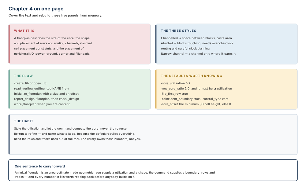
Where the next chapter goes, and why
There is now a boundary, a core, rows and tracks — and inside that boundary, blocks whose shapes are still nominal and one category of thing that has no shape at all. A black box is a block whose contents do not yet exist: a module that will be designed later, or bought, or is still being written, but which has to be planned around today. Chapter 5 handles them: how to identify which modules are candidates, how to create black box references, how to give a black box a timing model so the rest of the chip can be timed against it, and what the power intent has to say about something that is not there yet.
The connection to this chapter is direct and slightly uncomfortable. Chapter 1 mentioned that a black box needs a target area or a utilisation before it can be shaped, and this chapter has just shown where that number lands: in the same core area arithmetic, competing with everything else, for a block nobody has designed. That is the reason black boxes come immediately after the floorplan rather than at the end — an unsized unknown is the one thing a floorplan cannot absorb late.