CHAPTER THREE
Splitting Constraints: One Chip's Rules, One File per Block
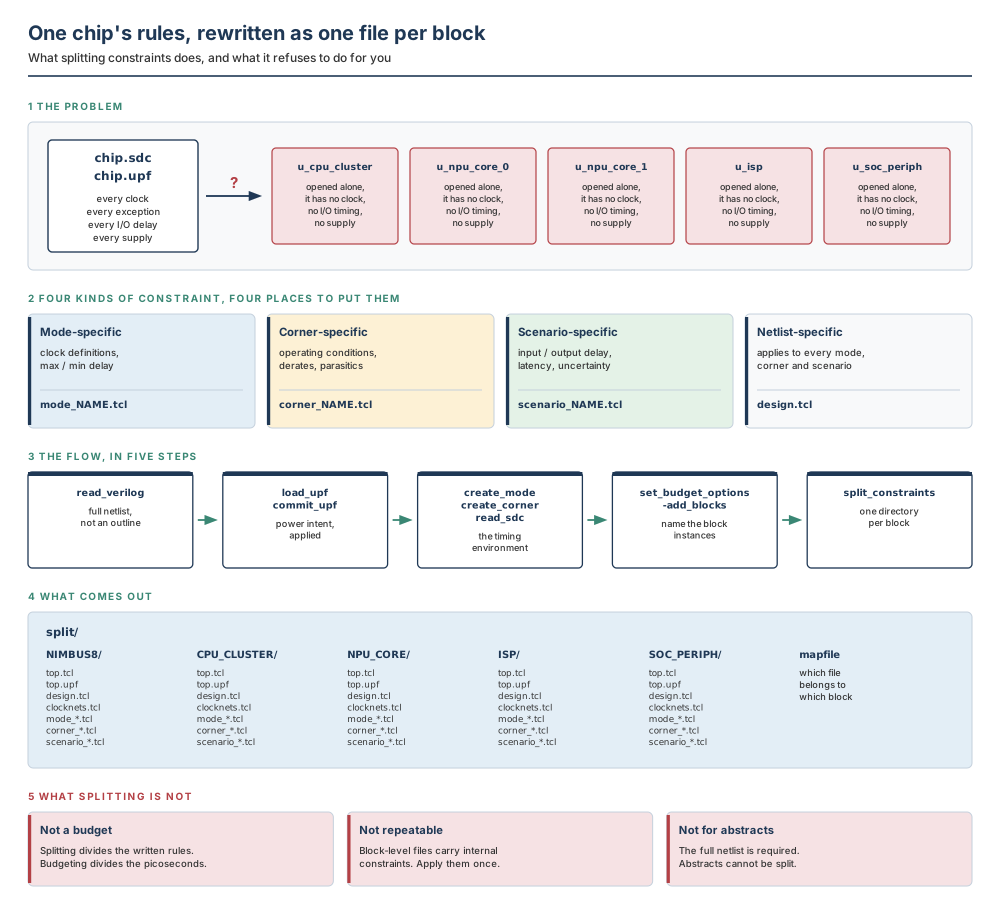
By the end of this chapter you will be able to take a single chip-level constraint set and turn it into one constraint set per block that a block owner can apply on their own, without guessing; to say exactly which constraint lands in which output file and why; to predict what happens to a clock, an I/O delay and an exception that crosses a block boundary; and to prove that the split is complete before anybody builds anything on top of it.
Why this chapter matters in a real project
Chapter 1 divided a chip into blocks. Chapter 2 made the session that does the work repeatable. Neither chapter gave a block owner anything they could open on their own — and that is the gap this chapter closes.
A block, opened by itself, is a netlist with no clock. It has no arrival times on its inputs, no required times on its outputs, no operating conditions, and no supply. Every number a block owner needs comes from a document written about the whole chip, and that document is useless to them in the form it arrives in: most of it is about other people's logic, the parts that are about theirs are phrased in coordinates they cannot see, and the paths that matter most — the ones that start outside the block and end inside it — are described from a viewpoint they do not have.
What happens next in a badly run project is predictable. Each block owner reads the chip-level file, deletes what looks foreign, invents the numbers that are missing, and starts optimising. Six weeks later the blocks all meet timing and the chip does not, and nobody can point at the decision that caused it, because there was no decision — there were four different sets of guesses that were never written down. The commands in this chapter exist to replace those guesses with a document, and the discipline in this chapter exists because the document is easy to produce and surprisingly easy to apply wrongly.
Prerequisites
Chapter 1: logical and physical hierarchy, what committing a block means, multiply instantiated blocks and feedthroughs, and what a timing budget is for. Chapter 2: how to start a session that configures itself, how to ask the tool what an option does, and why a block-level file that is applied twice is worse than one that is never applied. You do not need to have written SDC before; the constraint categories used here are introduced from first principles.
Learning objectives
- Explain why chip-level constraints must be partitioned before block-level work can begin, and when you may skip the partitioning entirely.
- Classify a constraint as mode-specific, corner-specific, scenario-specific or netlist-specific, and name the output file each one is written to.
- Build a mode, corner and scenario grid and read constraints into the right cell of it.
- Run the split flow in the correct order, and say what each step would break if it were left out.
- Predict what a top-level file keeps, what a block-level file receives, and what happens to an exception that crosses a block boundary.
- Say how a multiply instantiated block is treated, and what must be true of its instances for the result to be trustworthy.
- Read the constraint mapping file, assign it, and use it to apply constraints block by block.
- Distinguish splitting constraints from writing timing budgets, and state the ordering rule that connects them.
3.1 The beginner's mental model
Start with a building
A large building is described twice. Once as a specification for the whole building: the lift shall reach the ninth floor in twenty-four seconds, the lobby floor shall be level with the street, cabling shall run from the basement to every riser. And once as a set of contracts, one per trade: this is your part of the east facade, this is the load the steel above you will carry, this is where the basement feed arrives at your riser box.
Both documents describe the same building, and only one of them can be handed to a bricklayer. Give him the whole-building specification and he has three questions it cannot answer — which of these clauses is mine, where does my work start and stop, and what may I assume the other trades will have done. Nothing in the document answers him, so he decides for himself, and so does every other trade, differently.
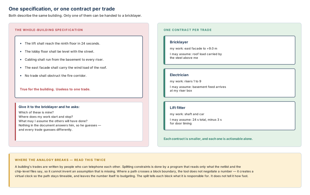
A building's trades are written by people who can telephone each other, and a missing assumption gets filled in by a conversation. Splitting constraints is done by a program that reads only the netlist and the chip-level files, so it cannot invent an assumption that is absent. Where a path crosses a block boundary, the tool does not negotiate a number — it creates a virtual clock so the path remains timeable inside the block, and leaves the number itself to budgeting. The split tells each block what it is responsible for. It does not tell it how fast.
Now the engineering model
To generate timing budgets at all, the chip-level constraint files must first be partitioned into a top-level file and a block-level file for each block. There are two of them to partition, and they travel together: the timing constraints, written in the Synopsys Design Constraints format, and the power intent, written in the Unified Power Format.
The command that does the partitioning is split_constraints. Given the full chip and a list of blocks, it writes a directory of constraint files for each block and one more for the top level. Afterwards, the top-level constraint file contains the top-level power intent and all of the top-level and top-to-block boundary timing, with the block-level internal constraints removed; the tool uses those top-level constraints to constrain the top-level logic when abstract views of the blocks are in use. The block-level files contain the internal constraints for each block, and are what the block owner applies during block-level optimisation.
There is an honest way to skip this chapter's command. If you already have block-level SDC and UPF constraints for your design — written by hand, or inherited from a previous project — you do not need to run split_constraints at all. What you cannot skip is the requirement behind it: before any timing budget is applied, every block must have had constraints applied, from one source or the other.
Do not confuse these
| This | Not this | How to tell them apart in one question |
|---|---|---|
| Splitting constraints | Writing budgets | Does the output contain a number describing how fast the block must be? If no, you are splitting. Splitting divides the written rules; budgeting divides the picoseconds. |
| Chip-level SDC | Block-level SDC | Whose ports does it name? The chip-level file names chip ports and full instance paths; a block-level file names that block's own ports and its own internal pins. |
| Mode | Corner | Is it about what the chip is doing, or the conditions it is doing it in? A mode is a functional mode; a corner is a set of conditions. A scenario is one pairing of the two. |
| Instance path | Block name | Which one did you type? You name instance paths when declaring blocks; the tool names the output directories after the blocks. |
| A real clock | A virtual clock | Does anything in the netlist drive it? A virtual clock has a waveform and no source. It exists so a path that used to start outside the block still has something to start from. |
| Full netlist view | Abstract view | Can the tool see inside every block? split_constraints needs the full netlist; abstracts cannot be split. |
mapfile | top.tcl | Does it contain constraints, or only file names? The map is an index — block, type, file name. top.tcl is the file that actually applies a block's constraints. |
3.2 The concepts, built in dependency order
3.2.1 Why one document cannot serve both levels
Take the simplest path that crosses a boundary: a flip-flop outside a block launches, a gate inside the block is in the middle, a flip-flop outside the block captures. One path, one clock, one exception on it. Now ask what each level needs to know about it.
The top level needs to know that the path exists and passes through the block, so that when the block is replaced by an abstract view the path is still there to be timed. It does not need the gate. The block needs to know that a signal arrives at one of its input ports, passes through its gate, and leaves by one of its output ports, and that an exception applies to it. It does not need the flip-flops, which it cannot see.
Neither description is a subset of the other, and neither is a truncation of the chip-level file. They are two rewritings of the same fact from two viewpoints, and producing them mechanically is what split_constraints is for.
3.2.2 Four kinds of constraint, and the four files they land in
The output file set looks arbitrary until you know that the tool classifies every timing constraint into one of four kinds, and that the classification is what decides the file.
Mode-specific constraints define or modify the timing graph — the weighted graph that represents the circuit's timing. Clock definitions belong here, and so do maximum and minimum delay constraints. At a minimum, the mode-specific constraints must contain a clock definition for every clock signal; a mode without one describes a circuit in which nothing is timed.
Corner-specific constraints modify the delay calculated on an object. Operating conditions, port load capacitances, parasitic information and scaling factors, and timing derating factors all belong here. These are the constraints that answer "how slow is this gate today", and nothing in them mentions a clock.
Scenario-specific constraints have a delay value and refer to a modal object such as a clock. Input and output delays belong here, and so do clock characteristics such as latency, uncertainty and transition. At a minimum, the scenario-specific constraints should contain an input delay or an output delay for every I/O port — which is exactly the set of numbers a block opened on its own is missing.
Netlist-specific constraints apply to all corners, modes and scenarios. Ideal network settings are the example to remember: what set_ideal_network sets is netlist-specific. They can apply globally to all designs or locally to a specific design.
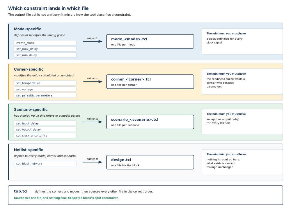
Why not write one file per block and be done? Because a block is analysed in more than one mode and more than one corner, and the constraints for those combinations are not interchangeable. Splitting the output the same way the tool splits the concepts means a block owner can read one corner file to answer a corner question, and it means the top-level and block-level files can be diffed against each other file by file. One large file per block would hide exactly the differences you need to see.
3.2.3 Modes, corners and scenarios: three names, one grid
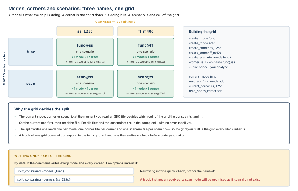
A block might operate under several different sets of conditions — different temperatures and voltages — and in several different functional modes. For timing analysis, each set of conditions is represented by a corner and each functional mode by a mode. A scenario is a combination of a corner and a mode, and it is the thing on which analysis and optimisation are actually performed.
Before you work on a block you must define the modes, corners and scenarios it uses, and define the constraints associated with them. Modes are created with create_mode and corners with create_corner, each with a unique name. Scenarios are created with create_scenario; by default a new scenario combines the current mode with the current corner, and -mode and -corner name them explicitly.
#=============================================================
# Two modes, two corners, and the scenarios you will analyse
#=============================================================
create_mode func
create_mode scan

create_corner ss_125c
create_corner ff_m40c

create_scenario -mode func -corner ss_125c -name func@ss
create_scenario -mode scan -corner ss_125c -name scan@ss
When you create a scenario it is active by default and becomes the current scenario; its mode becomes the current mode and its corner becomes the current corner. Reading is symmetrical with writing: current_mode, current_corner and current_scenario with no argument report what is current, get_modes, get_corners and get_scenarios return collections you can filter, and report_modes, report_corners and report_scenarios print the detail, including which scenarios belong to a mode or corner and which analysis types are active for them.
3.2.4 Reading constraints into the right cell
Constraints are specified either by loading SDC files with read_sdc or by using individual SDC commands. The mechanism that decides where a constraint lands is the current mode, corner or scenario at the moment you read it. Depending on the constraint's type, what you read applies to the current scenario, or to its associated mode, or to its associated corner.
That gives a procedure with a fixed order. Split the block's constraints into a mode-specific file for each mode, a corner-specific file for each corner, a scenario-specific file for each scenario, and a global file for the block. Define all the modes, corners and scenarios. Then set the current mode, corner or scenario appropriately before you apply the corresponding constraints.
# Set the current one first, then read. Never the other way round.
current_mode func
read_sdc func_mode.sdc

current_mode scan
read_sdc scan_mode.sdc

current_corner ss_125c
read_sdc ss_corner.sdc

current_scenario func@ss
read_sdc func_at_ss_scenario.sdc
Read a mode file while the wrong mode is current and the constraints are applied — to the wrong mode. Nothing fails. Nothing is reported. The design now has a scan clock in its functional mode, or a functional exception in its scan mode, and the first symptom will be a timing result that is inexplicably optimistic or pessimistic several steps later. The habit that prevents it costs one line: print current_mode and current_corner immediately before every read_sdc, in the script, so the log shows where each file went.
One more thing about units, carried straight from Chapter 2. If an SDC file does not contain unit settings, they are derived from the main logic library. If it does contain unit settings, they must be consistent with those in the main logic library. So the unit report you learned to put at the top of every script earns its place here too: an SDC file whose units disagree with the library is a problem you want to find at read time and not at hand-off time.
3.2.5 What each side of the boundary receives
Here is the mechanism, on the smallest design that shows it. A launch flop ff1 and a capture flop ff2 are at the top level. Between them, inside block i1, sits a gate a1. The chip-level file has three lines in it: a clock, an input delay, and a multicycle path exception that starts at the launch flop's clock pin and passes through the gate's output inside the block.
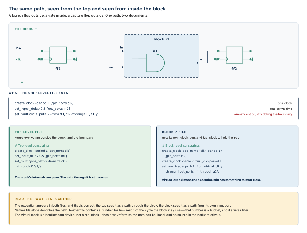
The top-level file keeps the clock, keeps the input delay, and keeps the exception with the block's internal pin still named in it. Nothing about the block's insides survives, but the path through the block does.
The block-level file is more interesting. It gets a clock of its own, added by name so that it coexists with whatever else defines that clock. And it gets a second clock that does not exist in the netlist — a virtual clock, with a period and no source. The exception is then rewritten to start from that virtual clock and to pass through the block's own input port and its own internal pin.
Why invent a clock? Because the exception's original starting point was a flip-flop the block cannot see. Delete the start point and the exception becomes meaningless; keep a reference to something outside the block and the block will not link. A virtual clock is the third option: an object with a waveform, so the path can be timed, and no driver, so nothing in the netlist has to exist for it. The same device does the heavier job described in §3.2.6.
3.2.6 Multiply instantiated blocks, and the four ways the top level disagrees with itself
A multiply instantiated block is one module used more than once. The command has a limited capacity to handle them, and what it does is specific: it creates a single combined set of constraints for each block. One module, one set of constraints, however many instances there are.
That immediately raises the question of what happens when the top level constrains the two instances differently, and there are four documented answers.
If a constant propagates from the top level to the block's boundary and the same constant feeds every instance, the constant is applied in the split constraints for the block — and the same thing happens again when budgets are written. If the constant is not present for every instance, a warning is issued and the constant is not applied at all. If a timing exception such as a false path or a multicycle path straddles the boundary of a multiply instantiated instance, the exceptions are pushed down using dedicated virtual clocks on the block ports, which keeps the timing paths and their constraints separate from each other when the block is timed; this too is repeated when budgets are written. And everything else — the clocks, the internal timing exceptions — is pushed down based on the first instance in the list. The other instances are ignored.
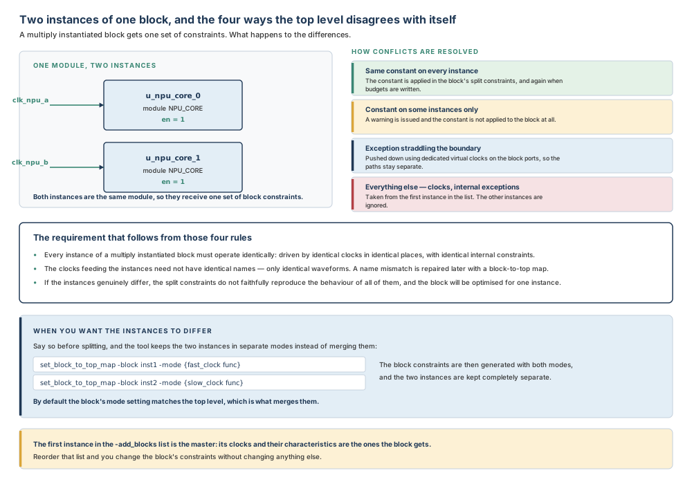
Those four rules add up to a requirement rather than a suggestion. It is required that the core of every instance of a multiply instantiated block operate identically: driven by identical clocks in identical places, with identical internal constraints. If they are not, the split constraints do not faithfully reproduce the behaviour of all of the instances. Note the one thing that is not required — the top-level clocks feeding the blocks do not need identical names, only identical waveforms; a name mismatch is adapted later with set_block_to_top_map.
There are also cases where you genuinely want the instances to work in different modes: one clocked fast and one slow, or configured by different constant values on their inputs. That is legitimate, and it is arranged by saying so before splitting.
# Say it before splitting, and the two instances are kept apart
# instead of being merged into one mode.
set_block_to_top_map -block inst1 -mode {fast_clock func}
set_block_to_top_map -block inst2 -mode {slow_clock func}
By default the command creates block constraints with a mode setting that matches the top level, which is what merges the two instances. With the map above, the block constraints are generated with two modes, and the constraints for the two instances are kept completely separate; no merging occurs.
3.2.7 Power intent travels the same road
The power intent is partitioned alongside the timing, and it needs two commands before the split rather than one. load_upf reads the UPF constraints; commit_upf applies them to the design and, in doing so, tries to resolve any conflicts between the power intent described in the UPF file and the actual power and ground nets in the design. Before commit_upf is executed, every instance in the design must belong to a power domain.
Each block directory then receives a top.upf of its own. One consequence is worth knowing in advance, because it looks like a defect the first time you see it. In a hierarchical flow, a block's strategies may refer to supply sets or supply nets that live outside that block. To keep those references resolvable once the block is separated, the tool creates a reference-only supply set or supply net in the block's UPF. It exists solely to resolve supply references in strategies; you cannot use it to power actual cells.
You can split one of the two documents on its own with -sdc_only or -upf_only. Both are useful while you are debugging a split — the SDC pass is much the more interesting of the two to inspect — and neither belongs in the hand-off, because a block that receives timing without power intent, or the reverse, will fail the readiness check that comes next and will waste somebody's afternoon before it does.
3.2.8 Instances go in, blocks come out
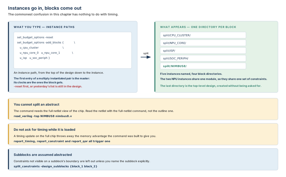
Before the split runs, you declare which blocks are to be budgeted, using set_budget_options. Two options matter here: -reset, which removes all previously specified budget constraints from the current design, and -add_blocks, which must be accompanied by a list of instance path names. -remove_blocks takes a list, or -all, and undoes an -add_blocks.
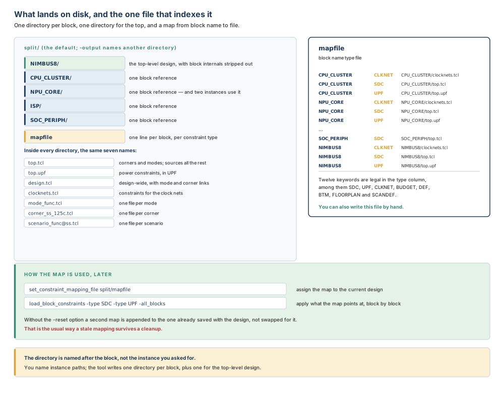
What you type is instance paths. What appears on disk is one directory per block, named after the block, plus one named after the top-level design. For a design with two instances of the same module, that means five instances named and four block directories written — which is the same fact as §3.2.6 seen from the file system.
3.2.9 Why the full netlist, and why you must not ask for timing
The command requires the full netlist view of your chip. You cannot use abstracts to generate constraints with it, and you must read the netlist with read_verilog — read_verilog_outline cannot be used for this step. For a large chip, that full netlist view can consume a significant amount of memory.
The command is specifically designed to use less memory than other commands that process design constraints: in particular, it processes constraints without calculating or propagating delay values, which greatly reduces its memory overhead. That design decision comes with a condition attached. To preserve the memory advantage, you must not trigger a timing update while the full-chip netlist is loaded — which means not running report_timing, report_constraint or report_qor. After the command completes, you can bring memory back under control by using abstracts in your design.
The natural instinct after loading a full chip is to check that it looks right, and the natural way to check is a timing report. Do that here and you have spent the memory the command was written to save you, on a full-chip timing picture you did not need and will not use. If you want reassurance that the netlist and constraints loaded, ask for something that does not update timing: the mode, corner and scenario reports, and the non-default application options.
3.2.10 Subblocks, and the two options that keep their constraints
A design with more than one level of physical hierarchy has blocks inside blocks. By default, when generating split constraints, the tool assumes that any subblock of a block is represented by a single-level abstract, and constraints that are not visible on the boundary of that abstract are not included.
Two options change that. -design_subblocks, given a list of block module names, retains all the internal constraints of those subblocks; the nested modules in the design hierarchy are then not abstracted when they are used in the context of their parent block. -hier_abstract_subblocks retains some extra internal constraints — the additional block-internal constraints that are necessary in the places where a hierarchical abstract has to be timed correctly — and is the option to use when you are telling the tool that those specific blocks are represented as hierarchical abstracts.
# One intermediate level of hierarchy, named explicitly.
split_constraints -design_subblocks {block_1 block_2}

# Or set it once for every block, with an application option.
set_app_options -name plan.budget.all_design_subblocks -value true
3.2.11 Splitting is not budgeting
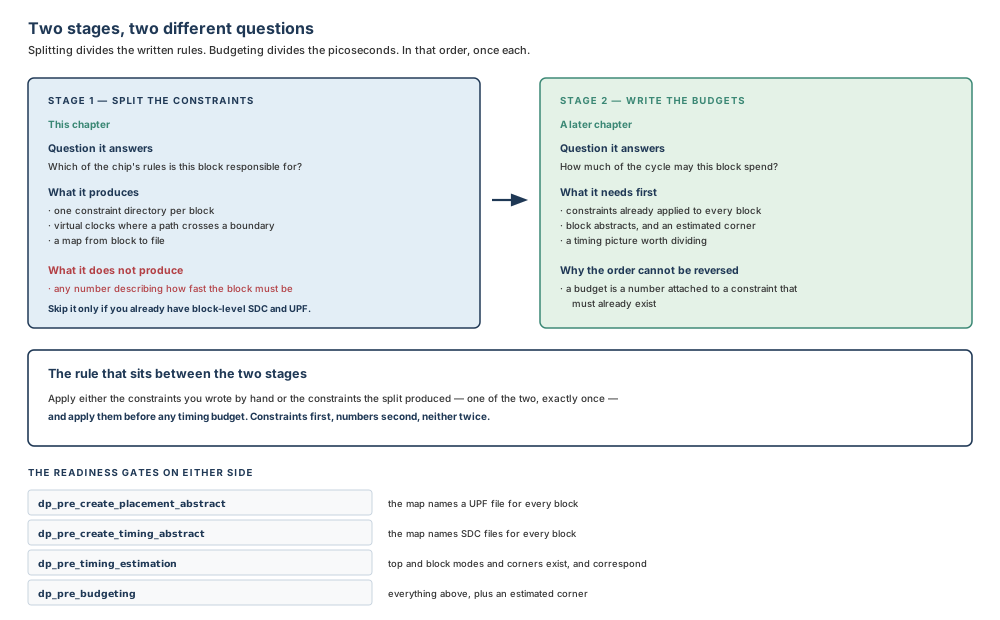
The two are adjacent in the flow and answer different questions, and the ordering rule between them is the one thing from this chapter most likely to be tested.
Splitting answers "which of the chip's rules is this block responsible for?" and produces constraint files. Budgeting answers "how much of the cycle may this block spend?" and produces numbers. The block-level constraint files generated by the split contain internal constraints for the block and should be applied only one time. And you must apply either manually generated constraints or constraints generated by the split before applying timing budgets.
3.3 Inputs, outputs and readiness
What has to be true before splitting is worth starting
| Input | Why the command needs it | Consequence if it is missing or wrong |
|---|---|---|
| The full Verilog netlist, read with the full-netlist command | Every path that crosses a boundary must be visible on both sides of it | Abstracts cannot be split. With an outline view the command has nothing to cut. |
| The chip-level UPF, loaded and committed | The power intent has to be applied to the design before it can be partitioned | No top.upf for the blocks, and the readiness check before placement abstracts will name the missing UPF. |
| Modes, corners and scenarios, defined | The output file set has one file per mode, per corner and per scenario | Constraints land in the wrong cell of the grid, or in no cell at all. No error is issued. |
| The chip-level SDC, read into the right cells | There is nothing to split until the constraints are in the design | A split that runs, succeeds, and writes files containing almost nothing. |
| The list of block instances | The command writes one directory per block you declared | A block nobody declared gets no constraints, and its owner will invent them. |
What the split leaves behind
The command creates a subdirectory for each declared block under the output directory, named after the block, and one more corresponding to the top-level design. Inside each directory the same file names appear.
| File | What it contains |
|---|---|
| top.tcl | Corner and mode definitions, and it sources all the other files in the correct order. Source only this file to apply the split constraints for that block. |
| top.upf | The power constraints, in UPF format. |
| design.tcl | Design-wide constraints with their mode and corner associations. Contains set_corner_status commands that configure the analysis settings for mode and corner combinations. |
| clocknets.tcl | Constraints for the clock nets. |
| mode_modename.tcl | Mode-specific constraints — clocks, exceptions, latencies and so on. One file per defined mode. |
| corner_cornername.tcl | Corner-specific constraints — derating factors, parasitic definitions and PVT values. One file per defined corner. |
| scenario_scenarioname.tcl | Scenario-specific constraints — clock latency, clock uncertainty and other factors. One file per defined scenario. |
Alongside the directories, the command writes one more thing: the constraint mapping file, mapfile, which lists the SDC and UPF constraint files for each block. Each line has three fields — the block design name, a constraint type keyword, and the file name with its path.
Preflight checklist
- The netlist was read with the full-netlist command, and
current_designshows the design representation rather than an outline. - The UPF was loaded and committed, and every instance belongs to a power domain.
- Every mode, corner and scenario you intend to hand over exists — check with
report_modes,report_cornersandreport_scenarios. - Every SDC file was read with the intended mode, corner or scenario current, and the log shows which.
- The unit report was printed once, at the top of the run, and the SDC files agree with the library.
set_budget_options -resetran before-add_blocks, so no stale block list survives.- Every committed block appears in the
-add_blockslist, and the master instance of any multiply instantiated block is first. - Instances that must be constrained differently were mapped with
set_block_to_top_mapbefore the split, not after. - No timing report has been run since the full netlist was loaded.
- The output directory either does not exist or you have decided to overwrite it with
-force.
When the result is not trustworthy
| Condition | What it looks like | Why it matters |
|---|---|---|
| The instances of a multiply instantiated block are not identical | The split completes; no error appears | The block gets one set of constraints, taken from the first instance. The other instances are optimised against somebody else's context. |
| A constant reaches only some instances | A warning in the log, easily lost | The constant is not applied at all, so the block is optimised without a configuration the chip actually applies. |
| Only part of the grid was written | Fewer mode_* or corner_* files than you have modes or corners | A block that never receives its scan mode will be optimised as though scan did not exist. |
| A multi-level hierarchy was split with the defaults | Subblock-internal constraints are absent | Subblocks are assumed to be single-level abstracts, so anything not visible on their boundary was left out. |
The readiness gates on either side
Two of the design-planning checks introduced in Chapter 1 exist precisely to catch an incomplete split, and they check the map rather than the constraints. dp_pre_create_placement_abstract checks that the constraint mapping file specifies a UPF file for all blocks, and that the Verilog files are in place for the outline view for blocks. dp_pre_create_timing_abstract checks that the constraint mapping file specifies SDC files for all blocks.
Two more sit further downstream and will fail for reasons that begin here. dp_pre_timing_estimation checks that the top and block levels have defined modes and corners, that the top-level modes and corners have corresponding block-level ones, and that the top level contains at least one clock, at least one scenario using a nonestimated corner, and that the corner has parasitic parameters. dp_pre_budgeting performs the same checks and additionally requires that the estimated corner is available.
# Run the two that belong to this chapter, before anything is built.
check_design -checks {dp_pre_create_timing_abstract}
check_design -checks {dp_pre_create_placement_abstract}
3.4 The guided workflow
3.4.1 A session from launch to hand-off
Eleven steps. The first four are Chapter 2's habits applied to this task; the middle four are the split itself; the last three are the proof.
- Start design planning mode from the project directory, so the project setup file is the one that configures the session.
- Print the units and the non-default application options, so the log records what this run assumed.
- Read the full Verilog netlist, naming the top module.
- Load the chip-level UPF, then commit it.
- Create every mode and corner, then every scenario you will analyse.
- For each SDC file: set the current mode, corner or scenario, then read the file.
- Reset the budget options, then declare the block instances with the master first.
- Map any instances that must be constrained differently.
- Run the split, into a named output directory.
- Assign the resulting map, and read it once with your own eyes.
- Run the two readiness checks, and only then save the library.
3.4.2 Command by command
Eight commands carry this chapter. Each gets the same treatment: what it is for, its syntax in plain English, what to expect, how to verify it, the common mistakes, what must be true first, and where to find the rest.
read_verilog — bring in the whole chip
Purpose. Read the full-chip Verilog netlist, so that every path crossing a block boundary is visible on both sides.
Syntax in plain English. -top names the top module; the file names are positional. -library and -design name the design library and the design if you are not relying on the current ones.
icc2_shell> read_verilog -top NIMBUS8 nimbus8.v
Expected result. The netlist is in the design, and current_design reports a design representation.
Verification. Ask current_design what it has. If the answer names an outline representation, you are not ready; expand it with expand_outline before continuing.
Common mistakes. Using the outline reader out of habit, because it is the right command in almost every other design-planning chapter and the wrong one here. Reading the netlist and then immediately asking for a timing report.
Prerequisites. The design library exists and the netlist file is on the search path.
Finding the rest. man read_verilog, and man read_verilog_outline for the command this step must not use.
load_upf and commit_upf — the power intent, read and then applied
Purpose. Read the chip's power intent, then apply it to the design so it can be partitioned with the timing.
Syntax in plain English. load_upf takes the file name; -scope reads it relative to a named instance, -supplemental loads a supplemental file, and -strict_check takes true or false. commit_upf takes no file at all — it acts on what was loaded — and -skip_resolve_pg_net suppresses the resolution of power and ground nets that otherwise happens at commit time.
icc2_shell> load_upf nimbus8.upf
icc2_shell> commit_upf
Expected result. The power intent is applied, and conflicts between the intent and the actual power and ground nets in the design have been resolved as far as the tool can resolve them.
Verification. The commit either reports its conflict resolution or reports an error naming an instance. An instance that belongs to no power domain is an error at this step, not later.
Common mistakes. Loading and not committing, which leaves the intent read but not applied. Splitting before the commit, which produces block UPF files describing an intent the design does not have.
Prerequisites. The netlist is loaded, and every instance belongs to a power domain.
Finding the rest. man load_upf, man commit_upf, and man reset_upf for the command that removes UPF constraints and restores a default single-voltage condition without touching the netlist.
The timing environment — eight commands that set the stage
Purpose. Give the design the modes, corners and scenarios the split will write one file each for, and the conditions that make delay calculation meaningful.
Syntax in plain English. For a design with multiple modes and corners you must use one or more of create_corner, create_mode, read_sdc, set_corner_status, set_parasitic_parameters, set_process_number, set_temperature and set_voltage. If your design uses UPF to describe the power network, you must use set_voltage for all supply net groups defined in the UPF file.
# Conditions, per corner.
icc2_shell> current_corner ss_125c
icc2_shell> set_temperature 125 -corners {ss_125c}
icc2_shell> set_voltage 0.72 -corners {ss_125c}
icc2_shell> set_process_number 1.0 -corners {ss_125c}
icc2_shell> set_parasitic_parameters -corners {ss_125c} \
   -late_spec rcworst_125c

# Which analyses this mode and corner combination is for.
icc2_shell> set_corner_status -modes {func} -corners {ss_125c} \
   -setup true -hold true
Expected result. Every scenario you intend to hand over exists, is active, and has conditions attached to its corner.
Verification. report_scenarios -all lists the scenarios with their modes, corners and active analysis types. report_corners -verbose gives the detail per corner.
Common mistakes. Reading an SDC file before setting the current mode or corner. Creating scenarios for combinations nobody will analyse, which produces scenario files that mislead a block owner into optimising for a case the chip never sees. Forgetting set_voltage for a supply net group in a UPF design.
Prerequisites. The netlist and the committed UPF.
Finding the rest. man create_scenario, man set_scenario_status for the analysis types a scenario can carry, and man set_corner_status for the same settings addressed by mode and corner.
set_budget_options — declare the blocks
Purpose. Tell the budgeting commands, of which the split is the first, which block instances are to have constraints created for them.
Syntax in plain English. -reset removes all previously specified budget constraints from the current design. -add_blocks must be accompanied by a list of instance path names. -remove_blocks takes a list of paths to remove, or -all. When multiply instantiated blocks are given in the list, the instance given first is considered the master instance, and the clocks associated with it and their characteristics are used in the generated budget.
icc2_shell> set_budget_options -reset
icc2_shell> set_budget_options -add_blocks {u_cpu_cluster \
   u_npu_core_0 u_npu_core_1 u_isp u_soc_periph}
Expected result. The design now carries a list of block instances, and nothing else has changed.
Verification. Count the directories after the split: one per block reference named, plus one for the top-level design. A count that is lower than you expected is a block you failed to declare or two instances that share a module.
Common mistakes. Skipping -reset, so a list from an earlier session or an earlier experiment is still in the design; the -reset also clears the pin, latency and boundary budget constraints and the computed ones, which is what you want at the start of a run and not what you want in the middle of one. Listing the wrong instance of a multiply instantiated block first, which silently chooses whose clocks the block inherits.
Prerequisites. The design is open and the instance paths exist.
Finding the rest. man set_budget_options. Most of that page is about budgeting rather than splitting — latency adjustment, hold-fixing and fixed-delay options — and belongs to a later chapter.
set_block_to_top_map — when the instances must differ
Purpose. Adapt a mismatch between a block's view of a clock, mode or corner and the top level's, before the split freezes one view of it.
Syntax in plain English. -block names a cell and -path names it by path; -auto_clock takes connected, local or all. -mode and -corner each take a pair, block first and top second; -clock takes a top mode, a block clock and a top clock; -inverted_clock and -unused_clock handle the two special cases. -report_only shows what the map would do without changing anything, and -ignore_waveform relaxes the waveform comparison.
icc2_shell> set_block_to_top_map -block inst1 -mode {fast_clock func}
icc2_shell> set_block_to_top_map -block inst2 -mode {slow_clock func}
Expected result. The block constraints are generated with both modes, and the constraints for the two instances are kept completely separate.
Verification. Run it with -report_only first and read what it says. After the split, the block's mode_*.tcl files should be one per mapped mode.
Common mistakes. Running it after the split, when the merge has already happened. Using it to paper over instances that differ in ways other than mode — a genuinely different internal constraint is not a naming problem.
Prerequisites. The netlist is loaded and the instances exist.
Finding the rest. man set_block_to_top_map.
split_constraints — the command this chapter is about
Purpose. Convert full-chip constraints into top-level and block-level constraints for a hierarchical design.
Syntax in plain English. Every option is optional, and the useful ones fall into four groups.
| Option | What it decides | Default if you say nothing |
|---|---|---|
| -output dir | Where the files are written | The ./split directory |
| -force | Overwrite an existing output directory | The command issues an error message and exits if the directory exists |
| -modes list | Which modes to write | All modes |
| -corners list | Which corners to write | All corners |
| -sdc_only / -upf_only | Split one document instead of two | Both the SDC and the UPF are split |
| -design_subblocks names | Keep all internal constraints of the named subblocks | Any subblock is assumed to be a single-level abstract |
| -hier_abstract_subblocks names | Keep the extra internal constraints hierarchical abstracts need | As above |
| -exclude list | Types of data to leave out of the output | All types of data are included |
| -include_scandef true | false | Also split the SCANDEF file | false, and it cannot be combined with -sdc_only or -upf_only |
| -compress gzip | none | Compress the output files | Compression is skipped and plain text is written |
| -nosplit | Write long constraint lines whole | Long lines are broken near column 80 with a continuation character |
| -verbose_level level | How much detail goes in the log | 0, and a higher number generates more output |
| -format format | Which tool the constraints are written for | Constraints are generated for Fusion Compiler and IC Compiler II only |
# The whole hand-off: both documents, all modes, all corners.
icc2_shell> split_constraints -output split -force

# A quick look at one mode while debugging. Not a hand-off.
icc2_shell> split_constraints -modes {func} -sdc_only \
   -output split_check -force

# Constraints for another tool in the chain.
icc2_shell> split_constraints -format pt -output split_pt -force
The valid -format values are fc for Fusion Compiler, icc2 for IC Compiler II, dc for Design Compiler and pt for PrimeTime.
Expected result. One directory per declared block, one for the top-level design, and a mapfile beside them.
Verification. Three things, in this order: count the directories; read the map; source one block's top.tcl in a throwaway session and see whether the clocks you expect appear.
Common mistakes. Running it on abstracts. Running a timing report first. Omitting -force and being surprised by an error on the second attempt, or including it and overwriting a hand-off somebody is already using. Narrowing with -modes or -corners for a debug run and then shipping that directory.
Prerequisites. Everything in Table 3.2.
Finding the rest. man split_constraints, and man write_script for the command whose output the block files resemble.
set_constraint_mapping_file — assign the index
Purpose. Tell the current design which map to use when later commands go looking for a block's constraint files.
Syntax in plain English. The file name is positional. -reset on its own removes the map from the current design; with a file name, the map in that file replaces the one saved with the design. Without -reset, the map in the file is appended to the map already saved with the design.
icc2_shell> set_constraint_mapping_file split/mapfile
icc2_shell> sh cat split/mapfile
Expected result. The design carries a map from block design name to constraint file.
Verification. Read the file. Every declared block should have an SDC line and a UPF line, and so should the top-level design.
Common mistakes. Assigning a second map without -reset and wondering why an old file is still being picked up. Editing the map by hand to point at a file that has since moved.
Prerequisites. A design is open, and the map file exists.
Finding the rest. man set_constraint_mapping_file. The legal constraint-type keywords are BUDGET, CLKNET, COMPILE_PG, DEF, ETM_UPF, PG_CONSTRAINT, CTS_CONSTRAINT, SDC, UPF, BTM, FLOORPLAN and SCANDEF.
load_block_constraints — apply what the map points at
Purpose. Load the constraints named in the map into the blocks they belong to, once.
Syntax in plain English. -type takes one of the same keywords the map uses, plus PRECHECK, and may be given more than once in a single command. Exactly one of -all_blocks and -blocks must be given: -all_blocks covers every child block of the current design and the current design itself, and in a multi-level hierarchy the tool works out the nesting order and runs the blocks bottom-up. -host_options and -work_dir hand the work to the distributed processing configuration from Chapter 2.
# What is the hierarchy, and what does the map say about it?
icc2_shell> load_block_constraints -type PRECHECK -all_blocks

# Then apply the timing and the power intent, in one command.
icc2_shell> load_block_constraints -type SDC -type UPF -all_blocks
Expected result. With PRECHECK, the tool prints information about the physical hierarchy tree of the design, and reports the map information for any other type given alongside it. Without PRECHECK, the constraints are loaded.
Verification. Run PRECHECK first, every time. It is a report, it changes nothing, and it tells you whether the map and the hierarchy agree before you act on either.
Common mistakes. Running it twice. Running it on a subset with -blocks, fixing something, then running it again on all blocks — which applies the subset's constraints for the second time.
Prerequisites. A map is assigned, and the files it names exist.
Finding the rest. man load_block_constraints.
3.4.3 Where a boundary delay comes from when nothing tells the tool
Four options change how the delay on a block's boundary pins is derived, and two of them have documented defaults you should know before you quote a number to anybody.
-internal_percent specifies the input and output delay percentage that serves as the internal block delay percentage, used to calculate the delay for the boundary pins of the block. -feedthrough_percent specifies the percentages used to calculate the delay value for the feedthrough pins of the block; if it is not specified, the feedthrough pins are budgeted at 25 percent of the available clock cycle. -no_logic_percent specifies the percentage used for paths with no logic gates; if it is not specified, those paths are budgeted at 50 percent of the available clock cycle.
Two options replace the flat share with a measurement. -logic_depth specifies that the delay for the boundary pins is calculated according to logic depth. -ignore_repeaters refines that by considering an odd or even number of buffers and inverters if any are present, and should only be specified together with -logic_depth.
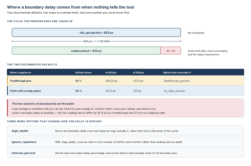
Both defaults are given as a percentage of the available clock cycle. For Nimbus-8's fastest clock that is either 625 ps, the full period, or 550 ps, what remains after the 45 ps of clock uncertainty and the 30 ps setup requirement from Chapter 1. Twenty-five percent of the first is 156.25 ps; of the second, 137.5 ps. Fifty percent gives 312.5 ps and 275 ps. The two readings differ by 18.75 ps and 37.5 ps respectively — on a 625 ps clock that is enough to change a conclusion. Confirm which cycle your release uses, with the in-tool help and a single measured path, before you quote a boundary delay to a block owner.
3.5 Worked example: splitting Nimbus-8's constraints
The situation
Nimbus-8 is the design from Chapter 1: a 3.44 mm die, a 3.20 mm core, four committed block references and one top-level hard macro. The partition is agreed and the floorplan style is settled. What does not yet exist is a single file that any block owner can open.
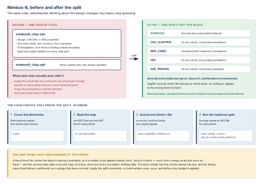
There is one chip-level SDC and one chip-level UPF. The SDC defines clk_cpu at 1.60 GHz — a period of 625 ps — one functional mode and one scan mode, two corners, and four scenarios. It carries 31 timing exceptions, 9 of which cross a block boundary, and input and output delays on every chip port. The UPF defines three supply sets and two power domains.
Four block teams have been asking for their constraints for a week. Two of them have started work anyway.
Step 1 — Start the session the way Chapter 2 taught you
% icc2_shell -dp_mode

icc2_shell> report_user_units
... time reads 1.00ps: the project convention, set by the setup file ...

icc2_shell> report_app_options -non_default
... one line: lib.setting.use_tech_scale_factor is true ...
Two commands, four seconds, and the log now records what this run assumed. Neither of them updates timing, which matters more in this chapter than in any other.
Step 2 — Read the whole chip, and prove that you did
icc2_shell> read_verilog -top NIMBUS8 nimbus8.v
icc2_shell> current_design
{nimbus8:NIMBUS8.design}
The representation is design, not outline. If it had read outline, the next command would be expand_outline and not the split.
This is the one step in the whole design planning flow where the outline reader is wrong. Every instinct built up in the floorplanning chapters says to read an outline and keep the memory small. Here the command needs to see inside every block, because a path that crosses a boundary has to be recognised on both sides of it before it can be described twice.
Step 3 — Load and commit the power intent
icc2_shell> load_upf nimbus8.upf
icc2_shell> commit_upf
... conflicts between the power intent and the PG nets resolved ...
Load reads; commit applies. Skip the commit and the split still runs, and writes block UPF files describing an intent the design does not actually hold.
Step 4 — Build the grid, then read the constraints into it
#=============================================================
# ./scripts/10_mcmm.tcl   —   the grid, then the constraints
#=============================================================

create_mode func
create_mode scan

create_corner ss_125c
create_corner ff_m40c

create_scenario -mode func -corner ss_125c -name func@ss
create_scenario -mode func -corner ff_m40c -name func@ff
create_scenario -mode scan -corner ss_125c -name scan@ss
create_scenario -mode scan -corner ff_m40c -name scan@ff

# Say where each file is going, in the log, before it goes there.
current_mode func   ; # echoed by the shell
read_sdc  sdc/func_mode.sdc

current_mode scan
read_sdc  sdc/scan_mode.sdc

current_corner ss_125c
read_sdc  sdc/ss_125c_corner.sdc
set_temperature 125 -corners {ss_125c}
set_voltage 0.72 -corners {ss_125c}

current_corner ff_m40c
read_sdc  sdc/ff_m40c_corner.sdc
set_temperature -40 -corners {ff_m40c}
set_voltage 0.88 -corners {ff_m40c}

# Which analysis each combination is actually for.
set_corner_status -modes {func} -corners {ss_125c} -setup true -hold true
set_corner_status -modes {scan} -corners {ss_125c} -setup true -hold true

report_scenarios -all
Two modes and two corners give four scenarios, and all four are analysed here, so the split will write two mode files, two corner files and four scenario files in every directory. With top.tcl, top.upf, design.tcl and clocknets.tcl, that is 4 + 2 + 2 + 4 = 12 files per directory.
Step 5 — Declare the blocks, master first
icc2_shell> set_budget_options -reset
icc2_shell> set_budget_options -add_blocks {u_cpu_cluster \
   u_npu_core_0 u_npu_core_1 u_isp u_soc_periph}
Five instances. u_npu_core_0 and u_npu_core_1 are the two instances of one module, and u_npu_core_0 is listed first, so its clocks and their characteristics are the ones the block inherits. That is a decision, taken here, deliberately: the two instances of Nimbus-8's NPU core are driven by clocks of identical waveform, and the first one is the instance whose context the block team has been reviewing.
Step 6 — Split
icc2_shell> split_constraints -output split -force
One command, no options beyond where to put the result and permission to overwrite it. Everything else — both documents, all modes, all corners, all types of data — is the default, and the default is what you want for a hand-off.
Step 7 — Prove it, with four checks in order
icc2_shell> sh ls split
CPU_CLUSTER  ISP  NIMBUS8  NPU_CORE  SOC_PERIPH  mapfile
Five instances were named and four block directories appeared, plus one named after the top-level design. The arithmetic is 5 − 1 = 4 block references, because two of the five instances share a module, and then 4 + 1 = 5 directories in total. A count you cannot explain is the first thing to investigate, and it is almost always either a block you failed to declare or a pair of instances you had forgotten were the same module.
| Quantity | Count | Where the number comes from |
|---|---|---|
| Instances declared | 5 | The -add_blocks list |
| Block references among them | 4 | Two of the five share one module |
| Directories written | 5 | 4 block references + 1 top-level design |
| Fixed files per directory | 4 | top.tcl, top.upf, design.tcl, clocknets.tcl |
| Mode files per directory | 2 | One per defined mode |
| Corner files per directory | 2 | One per defined corner |
| Scenario files per directory | 4 | One per defined scenario |
| Files per directory | 12 | 4 + 2 + 2 + 4 |
| Constraint files in total | 60 | 5 directories × 12 files |
| Lines in the map | 15 | 5 blocks × 3 types (SDC, UPF, CLKNET) |
icc2_shell> set_constraint_mapping_file split/mapfile
icc2_shell> sh cat split/mapfile
CPU_CLUSTER  CLKNET  CPU_CLUSTER/clocknets.tcl
CPU_CLUSTER  SDC     CPU_CLUSTER/top.tcl
CPU_CLUSTER  UPF     CPU_CLUSTER/top.upf
NPU_CORE     CLKNET  NPU_CORE/clocknets.tcl
NPU_CORE     SDC     NPU_CORE/top.tcl
NPU_CORE     UPF     NPU_CORE/top.upf
... ISP and SOC_PERIPH, three lines each ...
NIMBUS8      CLKNET  NIMBUS8/clocknets.tcl
NIMBUS8      SDC     NIMBUS8/top.tcl
NIMBUS8      UPF     NIMBUS8/top.upf
Fifteen lines, three per block, and one block per directory including the top. A missing UPF line here is exactly what the readiness check before placement abstracts is looking for, so finding it now saves a cycle.
# Third check: does one block's file actually work?
icc2_shell> source -echo split/NPU_CORE/top.tcl
... the clocks appear, including a virtual clock per pushed-down
    exception; no errors ...

# Fourth check: the gates.
icc2_shell> check_design -checks {dp_pre_create_timing_abstract}
icc2_shell> check_design -checks {dp_pre_create_placement_abstract}
Step 8 — Apply the constraints, once
icc2_shell> load_block_constraints -type PRECHECK -all_blocks
... the physical hierarchy tree, and what the map says about it ...

icc2_shell> load_block_constraints -type SDC -type UPF -all_blocks
icc2_shell> save_lib -all
The precheck runs first because it is free and it changes nothing. The load that follows is the step that must happen exactly once, and it is the reason the whole sequence lives in a script rather than in anybody's fingers.
Step 9 — What a senior engineer looks at next
- Are there as many mode files as modes? Compare
report_modeswithls split/NPU_CORE/mode_*.tcl. A mismatch means somebody narrowed the split. - Did the nine boundary exceptions survive? Grep the block files for the virtual clocks. Nine crossings should produce virtual-clock exceptions inside the blocks they cross into.
- Is there a warning about a constant? One warning about a constant that did not reach every instance of the NPU core is a real design question, not a log nuisance.
- Could a block owner reproduce this? The whole run is three scripts and one command. If it is not, the hand-off will decay by the third revision.
3.6 Failure modes and debugging
Each entry follows the same five-part shape: symptom, likely cause, diagnostic check, correction, prevention.
| Symptom | Likely cause | Diagnostic check | Correction | Prevention |
|---|---|---|---|---|
| The command exits with an error before writing anything | The output directory already exists | Look for the directory named by -output, or ./split if none was given |
Add -force, or choose a fresh output directory |
Name -output explicitly in the run script, and decide once whether that script may overwrite |
| The split runs and the files are nearly empty | The SDC was never read, or was read into the wrong cells of the grid | report_modes and report_scenarios -all, then look for the clocks |
Set the current mode or corner, re-read the SDC, re-split | Print current_mode and current_corner before every read_sdc |
| Memory grows until the run is killed | A timing update ran while the full chip was loaded | Search the log for report_timing, report_constraint and report_qor |
Remove the report and start again from the netlist | Nothing between the netlist and the split may update timing |
| A block has no directory of its own | Its instance was never declared | Read the -add_blocks list back out of the command log |
Add the instance path and re-split | Derive the block list from the committed blocks, not from memory |
| Fewer directories than instances named | Two or more instances share one module | Compare the instance names against the modules they reference | Nothing — this is the documented behaviour | Know which of your blocks are multiply instantiated before you count |
| A block inherits clocks that belong to the other instance | The wrong instance was listed first, so the wrong one is the master | Check the order of the -add_blocks list |
-reset, list the intended master first, re-split |
Choose the master deliberately and comment the choice in the script |
| A configuration constant the chip applies is missing from a block | The constant did not reach every instance of the block | Find the warning in the log; it is issued and easy to miss | Constrain the instances identically, or map them to different modes before splitting | Make multiply instantiated instances identical by design, not by repair |
| A block has two of every clock and two of every exception | The block-level file was applied more than once | Count clock definitions in the block after applying constraints | Reopen the block from a clean state and apply once | Apply constraints from one source, exactly once, before any budget |
| A block meets timing easily and the chip does not | The split was narrowed with -modes or -corners and that directory was shipped |
Count the mode_* and corner_* files against the defined modes and corners |
Re-split with no narrowing and re-issue the directory | Narrowed splits go to a differently named directory that is never handed over |
| A readiness gate fails naming a missing SDC or UPF file | The map is incomplete, or an old map was appended to rather than replaced | Read the map; every block needs an SDC line and a UPF line | Re-split, then assign the map with -reset |
Always assign a map with -reset unless you intend to append |
| A subblock's internal constraints are absent | The default assumes every subblock is a single-level abstract | Look for the subblock's internal constraints in the parent's files | Name the subblock with -design_subblocks, or set the application option for all blocks |
Settle how deep the physical hierarchy is before the first split |
The misleading one, in detail
Here is the failure that looks like a constraint problem and is not. A block owner reports that their block has suddenly become impossible: the same netlist that met timing yesterday now shows a large negative slack on almost every path, and the paths that fail are not the ones anybody expected. The obvious reading is that the split gave them constraints that are too tight, and the obvious response is to go and argue about the budget.
The constraints are fine. Somebody sourced the block's top.tcl twice — once from the block's setup script and once by hand, to check that it worked. A block-level file generated by the split contains the block's internal constraints, and it is written to be applied only one time. Applied twice, it adds a second definition of every clock and a second copy of every exception. Nothing fails. No error is issued. The block now has two clocks named clk_cpu, and every path is being checked against both of them.
The diagnostic is a count, not an analysis: ask the block how many clocks it has and compare that with how many the mode file defines. The correction is to reopen the block from a clean state and apply the constraints once. The prevention is the sentence from §3.2.11, which is worth memorising in the form it will be tested in: apply either the hand-written constraints or the split constraints, one of the two, exactly once, and before any timing budget.
In Chapter 2, a shape that was slightly the wrong size looked like a floorplan bug and was a library precision limit. Here, a block that cannot meet timing looks like a budget dispute and is a file applied twice. Both share a shape: the symptom appears in the layer where you were working, and the cause lives in the layer that fed it. When a symptom resists the obvious fix twice, stop fixing and go down one layer.
3.7 Hands-on mini lab
Goal
Turn one chip-level constraint set into a hand-off. Working on a small synthetic design called Corvus-4, you will build a mode and corner grid, declare the blocks, predict the output before you produce it, count what you get, and prove the arithmetic twice. No real design data is needed.
Supplied assumptions — Corvus-4
| Item | Value |
|---|---|
| Top module | CORVUS4 |
| Block instances to declare | u_dsp_0, u_dsp_1 (both of module DSP_CORE), u_mac (module MAC_ENGINE), u_io_ring (module IO_RING) |
| Fastest clock | clk_core, 2.00 GHz |
| Clock uncertainty | 40 ps |
| Setup requirement | 25 ps |
| Modes | func, scan |
| Corners | ss_125c, ff_m40c |
| Scenarios you will analyse | func@ss, scan@ss, func@ff — three of the four cells |
| Constraint types in the map | SDC, UPF, CLKNET |
| Exceptions crossing a boundary | 6 |
Steps
- Predict, before you run. Write down, on paper, how many directories the split will create, how many files will be in each one, how many constraint files there will be in total, and how many lines the map will have. Do not look at the answers below.
- Build the grid. Write
scripts/10_mcmm.tclthat creates both modes, both corners and the three scenarios, and that prints the current mode or corner immediately before eachread_sdc. - Set the conditions. Add a temperature and a voltage per corner, and a
set_corner_statusline for each mode and corner combination you analyse. Say in a comment why the fourth cell has none. - Declare the blocks.
-resetfirst, then-add_blockswith all four instances, withu_dsp_0as the master. Add a comment saying that it is the master and why that matters. - Split. Into a directory you name, with permission to overwrite. Nothing else.
- Count. List the output directory and compare every number with your predictions from step 1. Explain any difference before you change anything.
- Read the map. Confirm three lines per block, and that the top-level design has its own three.
- The unit arithmetic, done twice. Compute the period of
clk_core; then the usable period after uncertainty and setup; then the two documented default shares of each of those two numbers. Check each figure two ways: forwards from the frequency, and backwards from the picoseconds. - Apply, once. Assign the map, run the precheck, then load the SDC and UPF for all blocks. Write down what you would do if you were not sure whether somebody had already run that command today.
- Gate. Run both readiness checks from this chapter and record the result.
Expected observations
- Four instances named, three block references (
u_dsp_0andu_dsp_1shareDSP_CORE), so 4 directories: three blocks plusCORVUS4. - Files per directory: 4 fixed + 2 modes + 2 corners + 3 scenarios = 11.
- Constraint files in total: 4 × 11 = 44, plus the map itself.
- Lines in the map: 4 blocks × 3 types = 12.
- Period of
clk_core: 1 / 2.00 GHz = 500 ps. Backwards: 1 / 500 ps = 2.00 GHz. - Usable period: 500 − 40 − 25 = 435 ps.
- Feedthrough default, 25 %: of 500 ps it is 125 ps; of 435 ps it is 108.75 ps.
- No-logic default, 50 %: of 500 ps it is 250 ps; of 435 ps it is 217.5 ps.
- The two readings differ by 16.25 ps and 32.5 ps. Say which one your release uses before quoting either.
- Six boundary crossings should appear inside the blocks as virtual-clock exceptions.
- The honest answer to step 9's question is that you cannot tell from the block, so you reopen it from a saved clean state rather than guessing.
Stretch task
Repeat the prediction assuming u_dsp_1 must run in a slower mode than u_dsp_0. What changes about the directory count, and what has to be done, in which order, so that the two instances do not merge? Then say what would happen if you did that mapping after the split instead of before it.
3.8 Interview preparation
Sixteen questions, grouped by level. Answer each one out loud before reading the model answer; interviewers ask about this material for a specific reason, and it separates the candidates who have run a flow from the candidates who have watched one.
Beginner
BEGINNER
Q1. Why do chip-level constraints have to be split at all?
Because to generate timing budgets the chip-level SDC and UPF must be partitioned into top-level and block-level files, and because a block opened on its own has no clock, no I/O timing and no supply until it receives its own. The chip-level document is true about the chip and unusable inside a block: most of it concerns other people's logic, the parts that concern this block name pins the block cannot see, and the paths that matter most start outside the block. The top-level file that comes out is what constrains the top-level logic when abstract views of the blocks are in use; the block-level files are what the block owner applies during block-level optimisation.
What is being tested: whether you understand the flow's dependency rather than the command. A weak answer describes what split_constraints types out; a strong one explains why nothing downstream can start without it.
BEGINNER
Q2. Name the four categories of timing constraint and the output file each one goes to.
Mode-specific to mode_<mode>.tcl, corner-specific to corner_<corner>.tcl, scenario-specific to scenario_<scenario>.tcl, and netlist-specific to design.tcl. Mode-specific constraints define or modify the timing graph — clock definitions, maximum and minimum delay. Corner-specific constraints modify the delay calculated on an object — operating conditions, port loads, parasitics and scaling, derating. Scenario-specific constraints have a delay value and refer to a modal object — input and output delays, clock latency, uncertainty and transition. Netlist-specific constraints apply to every corner, mode and scenario; ideal network settings are the example. One more file, top.tcl, defines the corners and modes and sources all the others in the correct order.
What is being tested: whether you can explain the shape of the output directory. Candidates who have only ever sourced top.tcl cannot, and it shows the moment something is missing from one of the four.
BEGINNER
Q3. What is the difference between a mode, a corner and a scenario?
A mode is a functional mode — what the chip is doing. A corner is a set of conditions — what it is doing it in. A scenario is one combination of a mode and a corner, and it is the object on which analysis and optimisation are performed. You create them with create_mode, create_corner and create_scenario; a new scenario combines the current mode with the current corner unless -mode and -corner say otherwise, and it becomes the current scenario, making its mode and corner current too. You read them back with current_mode, get_corners, report_scenarios and their relatives.
What is being tested: the vocabulary the rest of the flow is written in. Merging mode and corner is the single most common vocabulary error at this level, and it makes every later answer imprecise.
BEGINNER
Q4. Walk me through the split flow in order.
Read the full netlist; load and commit the UPF; set up the timing environment with modes, corners, scenarios and their conditions; reset the budget options and declare the block instances; then run split_constraints. Two details in that sequence carry weight. The netlist must be read with read_verilog — the outline reader cannot be used for this step, because the command needs the full netlist view. And for a design with multiple modes and corners you must use one or more of create_corner, create_mode, read_sdc, set_corner_status, set_parasitic_parameters, set_process_number, set_temperature and set_voltage; if the design uses UPF for its power network, set_voltage must be used for all the supply net groups the UPF defines.
What is being tested: whether you know the order and can say what each step exists for. Reciting five command names without the two conditions is a memorised answer, and interviewers probe for exactly that.
BEGINNER
Q5. Where does the output go by default, and what happens if that directory already exists?
Into ./split, and if the output directory already exists the command issues an error message and exits unless -force is given. -output names a different directory. Inside it there is one subdirectory per declared block, named after the block, one more corresponding to the top-level design, and the constraint mapping file. That error on the second run is a feature: it stops a rerun from silently replacing a hand-off that somebody else is already working from.
What is being tested: whether you have actually run the command twice. Everybody meets this error; only people who have met it can say what the default directory is.
BEGINNER
Q6. What is the constraint mapping file, and what is it for?
It is a file called mapfile, written by the split, that lists the SDC and UPF constraint files for each block — one line per block per constraint type, with the block design name, a type keyword and the file name. You assign it to the current design with set_constraint_mapping_file, and load_block_constraints then uses it to apply the right file to the right block. The legal type keywords go well beyond SDC and UPF: BUDGET, CLKNET, COMPILE_PG, DEF, ETM_UPF, PG_CONSTRAINT, CTS_CONSTRAINT, BTM, FLOORPLAN and SCANDEF are all valid. You can also write the file by hand.
What is being tested: whether you see the map as infrastructure rather than a by-product. Two readiness checks in the design planning flow inspect the map and not the constraints, which is the give-away that it matters.
Intermediate
INTERMEDIATE
Q7. A multicycle path starts at a top-level flop and passes through a pin inside a block. What does each output file say about it?
The top-level file keeps the exception with the block's internal pin still named in it. The block-level file gets a virtual clock, and the exception is rewritten to start from that virtual clock and to pass through the block's own port and its own internal pin. The virtual clock is the mechanism worth naming explicitly: it has a period and no source in the netlist, so the path remains timeable inside the block even though its real start point is invisible there. The same device is used for exceptions that straddle the boundary of a multiply instantiated instance, where dedicated virtual clocks on the block ports keep the several instances' paths and constraints separate from one another.
What is being tested: whether you can describe a mechanism rather than an outcome. Candidates who say "the exception is pushed down" and stop cannot then explain why the block links at all.
INTERMEDIATE
Q8. You declare five block instances and only four block directories appear. Is that a bug?
No. You name instance paths; the tool writes one directory per block, named after the block. Two of the five instances are instances of the same module, and a multiply instantiated block gets a single combined set of constraints. Counting is still the right instinct — it is the first of the checks worth running — but the arithmetic is instances minus duplicates, plus one directory for the top-level design. A count you cannot explain is either a block you forgot to declare or a pair of instances you had forgotten share a module, and both are worth five seconds of investigation before anything else.
What is being tested: the instance-versus-block distinction, which is the commonest confusion in the whole chapter and has nothing to do with timing.
INTERMEDIATE
Q9. What must be true of the instances of a multiply instantiated block, and why?
Every instance must operate identically — driven by identical clocks in identical places, with identical internal constraints — because the block receives one combined set of constraints and everything but the boundary cases is taken from the first instance in the list. The four documented rules make the requirement unavoidable. A constant that feeds every instance is applied to the block; a constant that feeds only some produces a warning and is not applied at all; exceptions that straddle the boundary are pushed down with dedicated virtual clocks; and everything else, including the clocks and the internal exceptions, comes from the first instance while the others are ignored. The one relaxation is that the top-level clocks feeding the instances need not have identical names, only identical waveforms — a name mismatch is adapted later with set_block_to_top_map.
What is being tested: whether you know that this is a requirement on the design and not a capability of the tool. A weak answer says the tool handles multiply instantiated blocks, which is true and misses the point.
INTERMEDIATE
Q10. Compare splitting constraints with writing timing budgets. What is the ordering rule between them?
Splitting divides the written rules and produces files with no performance number in them; budgeting divides the picoseconds. You must apply either manually written constraints or the split constraints — and apply them only once — before applying timing budgets. The reason the order cannot be reversed is that a budget is a number attached to a constraint that must already exist. The reason the "only once" matters is that a block-level file generated by the split carries the block's internal constraints, so a second application adds a second copy of every clock and every exception without any error being reported.
What is being tested: whether you can hold two adjacent flow steps apart. This is the question most likely to be asked in some form, because getting it wrong in a real project costs weeks.
INTERMEDIATE
Q11. Why can you not split abstracts, and what must you avoid doing while the full netlist is loaded?
The command requires the full netlist view of the chip, so abstracts cannot be used; and while that netlist is loaded you must not trigger a timing update — no report_timing, report_constraint or report_qor. The command is deliberately built to use less memory than other commands that process constraints: it processes them without calculating or propagating delay values. A timing update discards that advantage on a design large enough that the advantage was the reason the command exists. After the split completes you can control memory by using abstracts in the design — but not before, and not during.
What is being tested: whether you understand a tool's performance contract. Candidates who have only run small designs answer the first half and have never heard of the second.
INTERMEDIATE
Q12. What do -design_subblocks and -hier_abstract_subblocks do, and when would you reach for each?
Both keep constraints that the default would discard. By default the tool assumes any subblock of a block is represented by a single-level abstract, so constraints not visible on that abstract's boundary are left out. -design_subblocks retains all of a named subblock's internal constraints; -hier_abstract_subblocks retains the extra internal constraints needed where hierarchical abstracts have to be timed correctly. You reach for the first when a subblock is genuinely going to be seen as a full design in its parent's context, and the second when you are telling the tool that those blocks are represented as hierarchical abstracts. The application option plan.budget.all_design_subblocks sets the first for all blocks, which is the pragmatic choice on a design where every level is being carried through.
What is being tested: whether you have worked on more than one level of physical hierarchy. On a single-level design neither option ever comes up, which is exactly why interviewers use it to separate candidates.
Scenario and debugging
SCENARIO / EXPERT
Q13. What would you do if a block owner says the split gave them constraints that are impossible to meet?
Before discussing the numbers, establish what was applied and how many times. Count the clocks in the block and compare that with the number the mode file defines. A block-level file applied twice has two definitions of every clock and two copies of every exception, and produces exactly this complaint with no error anywhere. If the count is right, the next checks are whether all the mode and corner files are present — a directory narrowed with -modes or -corners during debugging and then shipped will make a block look either impossible or suspiciously easy — and whether the block is the non-master instance of a multiply instantiated pair, in which case it has inherited a context that is not its own. Only when all three come back clean is it a budget conversation, and at that point splitting is the wrong chapter to be arguing about, because splitting produces no numbers.
What is being tested: whether you debug the process before the data. A candidate who goes straight to the timing report has just committed to the expensive path.
SCENARIO / EXPERT
Q14. What would you do if two instances of one block must run at different frequencies?
Map them to different modes with set_block_to_top_map before running the split, so the block constraints are generated with both modes and the two instances are kept completely separate rather than merged. The default is the trap: the command creates block constraints with a mode setting that matches the top level, which is precisely what merges the instances. Mapping -block inst1 -mode {fast_clock func} and -block inst2 -mode {slow_clock func} generates two modes in the block, and no merging occurs. The order is not negotiable — done after the split, the merge has already happened and the mapping repairs nothing. I would also run the map with -report_only first, because it costs nothing and tells me what the tool thinks I asked for.
What is being tested: whether you know that a documented default can be wrong for your design, and whether you can say what "before" means in terms of consequences rather than sequence.
SCENARIO / EXPERT
Q15. What would you do if a readiness check fails naming a UPF file that is missing for one block?
Read the map, not the constraints. The check before placement abstracts inspects whether the constraint mapping file specifies a UPF file for all blocks, so a failure means the map is incomplete or stale, not that the block's power intent is wrong. Three causes, in the order I would test them. The block was never declared, so the split never wrote it a directory. The split was run with -sdc_only, so no UPF was written for anybody. Or a second map was assigned without -reset and was therefore appended to the map already saved with the design, leaving an entry that points at a file which has since moved. The last of those is the one that survives a cleanup and reappears a fortnight later, so it is worth confirming even when one of the first two explains the symptom.
What is being tested: whether you read the check's own words. The check names the map; a candidate who starts opening UPF files has not read what failed.
SCENARIO / EXPERT
Q16. A colleague says the split is unnecessary on their project. Under what circumstances are they right, and how would you check?
They are right if they already have block-level SDC and UPF constraints for the design, in which case the split can be ignored entirely. What they cannot ignore is the requirement behind it: constraints from one source or the other must be applied to every block, exactly once, before any timing budget. The way to check is not to argue but to run the two readiness gates and read the map. If every block has an SDC line and a UPF line pointing at files that exist, and if the modes and corners at the block level correspond to those at the top, the hand-written constraints are doing the job the split would have done. If any of those is missing, the split is not unnecessary — it is merely not yet run, and the difference will show up as a block optimised against numbers somebody invented.
What is being tested: whether you can distinguish a command from a requirement. This is a senior question: the correct answer agrees with the colleague on the command and holds the line on the requirement.
3.9 Chapter close
Sign-off checklist for a hand-off you would defend
- The netlist was the full one, and
current_designproves it. - The UPF was loaded and committed, and every instance belongs to a power domain.
- Every mode, corner and scenario you intend to hand over exists, and the reports show it.
- Every SDC file was read with the intended mode or corner current, and the log records which.
- No timing report ran between the netlist and the split.
-resetran before-add_blocks, and the master instance of every multiply instantiated block is first.- Instances that must differ were mapped before the split, not after.
- The directory count is explained: block references plus one for the top-level design.
- The file count per directory is explained: four fixed, plus one per mode, one per corner, one per scenario.
- The map has one line per block per type, including for the top-level design.
- One block's
top.tclwas sourced in a throwaway session and produced the clocks you expected. - Both readiness gates pass, and the hand-off directory is not a narrowed debug directory.
Key-concept flashcards
Chip-level SDC and UPF must be partitioned into top-level and block-level files before timing budgets can be generated.
Mode-specific defines the timing graph; corner-specific modifies calculated delay; scenario-specific has a delay value and refers to a modal object; netlist-specific applies to everything.
top.tcl. It defines the corners and modes and sources every other file in the correct order — source it and nothing else.
Mode is behaviour, corner is conditions, scenario is one combination of the two and is what analysis runs on.
./split. If it exists, the command errors and exits unless -force is given.
You name instance paths. The tool writes one directory per block, named after the block, plus one for the top-level design.
It has a waveform and no source, so an exception whose real start point lies outside the block still has something to start from.
One combined set of constraints per block; everything but the boundary cases comes from the first instance in the list.
Apply hand-written or split constraints — one of the two, exactly once — before any timing budget.
The command avoids calculating and propagating delays to save memory; a timing update on the full chip spends what it saved.
Feedthrough pins at 25 percent of the available clock cycle; paths with no logic gates at 50 percent.
Both of them: the placement-abstract gate wants a UPF file for every block, the timing-abstract gate wants SDC files for every block.
Compact glossary
| Term | Meaning as used in this book |
|---|---|
| Block-level constraints | The constraint files that contain a block's internal constraints, applied during block-level optimisation and applied only one time. |
| Constraint mapping file | mapfile: a list of block design names, constraint type keywords and file names, assigned with set_constraint_mapping_file. |
| Corner | A set of operating conditions under which a block is analysed. |
| Corner-specific constraint | A constraint that modifies the delay calculated on an object. |
| Feedthrough percentage | The share of the available clock cycle used to derive the delay for a block's feedthrough pins; 25 percent if nothing says otherwise. |
| Full netlist view | The design representation in which the tool can see inside every block. Required by the split; abstracts cannot be used. |
| Master instance | The first instance of a multiply instantiated block in the -add_blocks list, whose clocks and their characteristics the block inherits. |
| Mode | A functional mode in which a block operates. |
| Mode-specific constraint | A constraint that defines or modifies the timing graph, such as a clock definition or a delay constraint. |
| Netlist-specific constraint | A constraint that applies to all corners, modes and scenarios, such as an ideal network setting. |
| Reference-only supply | A supply set or net the tool creates in a block's UPF so that strategies referring to supplies outside the block still resolve. It cannot power actual cells. |
| Scenario | A combination of a mode and a corner, used to perform timing analysis and optimisation. |
| Scenario-specific constraint | A constraint that has a delay value and refers to a modal object, such as an input delay or a clock uncertainty. |
| Splitting constraints | Partitioning chip-level constraints into separate top-level and block-level constraints for a hierarchical design. |
| Timing budget | The number describing how much of a cycle a block may spend. Produced after constraints are applied, never by the split. |
| Top-level constraints | The file set containing the top-level power intent and all top-level and top-to-block boundary timing, without block-level internal constraints. |
| Virtual clock | A clock with a waveform and no source in the netlist, created so that a path whose real start point lies outside a block can still be timed inside it. |
Five-question self-check
- A design has seven block instances. Three of them are instances of one module; the other four each use a different module. How many directories will the split create, and why?
- You have three modes, two corners, and four scenarios you analyse. How many files will each block directory contain, and what are they?
- A clock runs at 1.60 GHz. A feedthrough pin is budgeted with the documented default. What delay does that give, and what is the one thing you must state alongside the number?
- The map for the design in question 1 lists SDC, UPF and CLKNET for every block. How many lines does it have?
- A colleague sources a block's
top.tcl, then sources it again to be sure. What is now true of the block, what error will they see, and how would you detect it?
Answers.
1. Six. Seven instances resolve to five block references — one shared by three instances and four used once each — and the tool writes one directory per block reference plus one named after the top-level design: 5 + 1 = 6. The directory is named after the block, not the instance, and a multiply instantiated block gets a single combined set of constraints.
2. Thirteen. Four fixed files — top.tcl, top.upf, design.tcl, clocknets.tcl — plus one file per mode, one per corner and one per scenario: 4 + 3 + 2 + 4 = 13. (Nimbus-8 in the worked example has two modes, so that count is 4 + 2 + 2 + 4 = 12. This question asked for three modes.) The three mode files, two corner files and four scenario files are the reason the classification in Section 3.2.2 is worth memorising.
3. The period is 1 / 1.60 GHz = 625 ps, and the documented default budgets feedthrough pins at 25 percent of the available clock cycle: 25 % × 625 ps = 156.25 ps. The thing you must state alongside it is what the percentage is a percentage of. If the available cycle is instead the usable period after 45 ps of uncertainty and a 30 ps setup requirement — 550 ps — the same 25 percent gives 137.5 ps, which is 18.75 ps less. A boundary delay quoted without its base is not an engineering number.
4. Eighteen. Six blocks, counting the top-level design, times three constraint types: 6 × 3 = 18 lines.
5. The block now has two definitions of every clock and two copies of every exception, because a block-level file from the split carries the block's internal constraints and is written to be applied only one time. They will see no error at all — which is what makes this expensive. Detect it by counting: ask the block how many clocks it has and compare that with the number the mode file defines. Recover by reopening the block from a clean saved state and applying the constraints once.
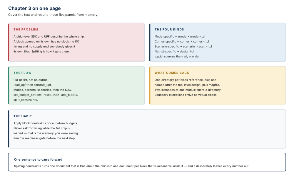
Where the next chapter goes, and why
Every block now has a document of its own, and not one of those documents says anything about where the block is. That is the next question, and it is the last preparation step before geometry becomes real: Chapter 4 creates the floorplan — the die and core, the supported floorplan styles, the netlist reading that starts it, and the commands that turn an area estimate into a boundary with rows and tracks in it.
The two chapters fit together more tightly than their titles suggest. The floorplan decides what the blocks can be; the constraints decide what they must do. A block whose shape is settled and whose constraints are missing cannot be worked on, and neither can a block with beautiful constraints and no boundary. Chapter 3 finished the second half of that pair, which is why the floorplan comes next rather than first.