Detailed Design Analysis
ECO Flow in ICC2: A Mentor Guide
What changed, how little can I disturb, and how do I prove I disturbed nothing else. The five ECO flows, spare cells and freeze silicon, the PrimeTime signoff loop, incremental signoff, ECO Fusion, and minimal-disturbance placement, taught the way a senior engineer would explain a repair to a new hire at their desk. The final chapter of the guide.
The chip is finished. Then something changes.
This is the last chapter of the guide, and it starts from a different place than the other seven. Nimbus‑8 is routed. It is finished. Chapter 6 signed off its density and its fill. Chapter 7 closed its hierarchy and handed off a checkpoint named nimbus8_top_hier_closed_v1. And then a late setup violation shows up on a u_sens_tile boundary path, or a functional bug is found, or a DRC escape turns up in a re-check. The chip has to change, without going back to floorplan and starting over.
The IC Compiler II User Guide defines an ECO — an engineering change order — as an incremental change to a complete or nearly complete design, used to fix functional, timing, noise and crosstalk violations without re-synthesizing, re-placing and re-routing everything. Read that definition twice, because both halves matter. It is incremental: you touch as little as possible. And it fixes real problems: functional bugs, timing violations, noise, crosstalk. An ECO is not a redesign wearing a smaller name.
The spine of this chapter
Every ECO you will ever run answers three questions, in this order, and this chapter is organized around them exactly:
What changed, how little can I disturb, and how do I prove I disturbed nothing else.
- What changed — identifying the delta between what you have and what you need.
eco_netlist, netlist editing commands, PrimeTime change lists. Parts 2 through 4. - How little can I disturb — the whole minimal-impact toolkit: which flow you are in, spare cells, freeze silicon, legalization modes, displacement thresholds. Parts 5 through 9.
- How do I prove I disturbed nothing else — recording, reporting, reverting, re-timing, and the closure gate. Parts 10 through 12.
A reader who finishes this chapter should be able to answer all three questions about any ECO they are handed. Refer back to this spine as each Part opens.
Why this chapter closes the series
Chapter 7 ended by handing off to ECO Flow by name. That was not an accident. Repairing a chip correctly demands everything the previous seven chapters taught. Placement legality comes from Chapter 4. Clock trees you must not disturb come from Chapter 5. Routing you must minimally reroute comes from Chapter 6. Fill and spare cells come from Chapter 7's chip-finishing. Block boundaries that constrain where an ECO may land come from Chapter 7's hierarchical implementation. This chapter makes those callbacks explicit as they come up.
Which of the five flows are you in?
Before you type a single command, answer one question: what are you still allowed to change? That single question, asked correctly, sorts every ECO into one of five flows, and the flow decides every command you type after this page.
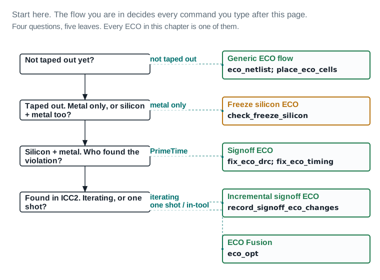
eco_netlist then place_eco_cells, because you can still add and move cells freely. If it has taped out, the next question is whether only metal may change: if so, you are in the freeze-silicon flow, starting with check_freeze_silicon. If silicon and metal can both change, the next question is who found the violation. PrimeTime finding it during signoff puts you in the signoff ECO flow (fix_eco_drc, fix_eco_timing). ICC2 finding it during its own optimization, with the loop iterating, puts you in incremental signoff ECO (record_signoff_eco_changes). A one-shot or in-tool fix puts you in ECO Fusion (eco_opt).| Flow | When you are in it | First command | Taught in |
|---|---|---|---|
| Generic ECO flow | Pre-tapeout, cells may still be added and moved | eco_netlist | Part 2 |
| Freeze silicon ECO | Taped out, only metal and via layers may change | check_freeze_silicon | Part 6 |
| Signoff ECO | PrimeTime signoff found the violation | fix_eco_drc | Part 7 |
| Incremental signoff ECO | The signoff loop is iterating and re-running it in full is too slow | record_signoff_eco_changes -start | Part 8 |
| ECO Fusion | A one-shot or in-tool fix invoking PrimeTime from inside ICC2 | eco_opt | Part 9 |
The worked ECO this chapter uses throughout
One concrete example runs through every part and every figure: a late setup violation on a u_sens_tile boundary path, found in the func_ss_0p72v_125c scenario at −0.008 ns. The fix is one buffer insert (eco_cell_1) plus one cell upsize (u_sens_tile/U88), alongside a small functional change adding a two-input gate on the sensor-enable path. Small enough to draw completely, real enough to teach the whole flow. Every figure that shows an ECO shows this one.
Is the design ready to take an ECO?
Before the first command in Part 2, a real ECO starts with a readiness check. Is the netlist in sync with the layout? Is there spare capacity nearby? Is the freeze-silicon mode set correctly for the flow you chose in Figure 1? Has the change file been reviewed, and is a baseline timing snapshot archived to compare against later? Dashboard 1 is that check, applied to the worked ECO.
An ECO is cheap to start and expensive to undo badly. This board exists so the decision to commit a change is made on evidence, not on habit.
| Item | Evidence | Source command / report | Threshold | Status | Required action |
|---|---|---|---|---|---|
| Netlist and layout in sync | |||||
| 1. Working netlist matches golden reference | 0 unexpected diffs outside the intended ECO | eco_ | 0 unexpected diffs | PASS | — |
| 2. Layout reopens clean from the signoff checkpoint | nimbus8_ reopens with 0 errors | checkpoint reopen | 0 errors on reopen | PASS | — |
| 3. Baseline timing archived before any edit | WNS -0.008 ns (func_), TNS -0.008 ns, archived | report_ | Archived before the first ECO command | PASS | — |
| 4. Scenarios loaded match signoff set | func_ss_0p72v_125c, func_ff_0p88v_m40c both loaded | scenario list review | Both signoff scenarios present | PASS | — |
| Item | Evidence | Source command / report | Threshold | Status | Required action |
|---|---|---|---|---|---|
| Spare-cell inventory and freeze-silicon mode | |||||
| 5. Spare-cell inventory sufficient for this ECO | 1 spare buffer-compatible cell within 5 µm | spare-cell inventory query | ≥ 1 compatible spare within the displacement budget | PASS | — |
| 6. Spare-cell inputs verified tied | 100% of inventoried spares have non-clock inputs tied | netlist scan | 100% tied | PASS | — |
7. eco_ set correctly for this flow | off — this ECO is pre-tapeout, silicon may change | design. | Matches the flow chosen in Figure 1 | PASS | — |
| 8. PSC utilisation headroom (if freeze silicon later) | 62% of PSCs unprogrammed, chip-level | PSC inventory | Headroom recorded even when not this ECO's flow | PASS | — |
| 9. Spare-cell distribution near the violation | Local spacing 71 µm against a 38 µm block average (Figure 9) | local density query | Local spacing within 1.5x the block average | REVIEW | Placement may need allow_move_other_cells locally if minimum_physical_impact rejects the first choice; watch Dashboard 5 after placement. |
| Change list reviewed | |||||
| 10. Change file read before sourcing | pt_eco.tcl reviewed: 1 add_buffer, 1 size_cell | manual review | Reviewed by a named engineer before source | PASS | — |
| 11. Change file signature matches current block | record_signoff_eco_changes signature check passes | record_ | Signature consistent | PASS | — |
| 12. Early data checks clear before the ECO | 0 BLOCKER, 0 REVIEW outstanding on the base design | report_ | 0 BLOCKER at ECO start | PASS | — |
Readiness verdict: 11 PASS, 1 REVIEW, 0 BLOCKER → GO, with one item to close before placement.
Read it: Read gate 9 first — the only REVIEW. The spare-cell distribution near the violation is thinner than the block average, which is exactly the gap that turns a minimum_physical_impact placement into a rejected cell.
Field values are this chapter's illustrative teaching data.
The four-step flow you use before tapeout
The generic ECO flow is the default: use it whenever you can still add cells and move existing ones, which is any time before tapeout. It is four steps, and every other flow in this chapter is a variation built to handle a constraint the generic flow does not have to worry about.
- Update the netlist. Identify and apply the logical change — Part 3 covers this in depth.
place_eco_cells. Place and legalize the new or changed cells.- Add filler. Rebuild filler cells around the change so density stays correct.
route_eco. Route the new or modified nets.
That is the whole flow. Everything this chapter adds after Part 2 — freeze silicon, the PrimeTime loop, incremental tracking, ECO Fusion — is this same four-step shape, adapted for one added constraint: silicon frozen, a second tool finding violations, or a loop that must run many times cheaply.
Filler cells and -post_eco
Standard-cell rows are packed with filler cells wherever there is no real logic, so the row is continuous for manufacturing and so density stays inside the window Chapter 6 signed off. An ECO opens a gap in that row to make room for a new cell, which means fillers have to come out before placement and go back in after. Doing that for the whole design every time is wasteful: only the touched cells need new fillers and re-checked DRC.
create_stdcell_fillers -post_eco and remove_stdcell_fillers_with_violation both exist to scope this work down to what changed. The -post_eco option tells create_stdcell_fillers to run its DRC checking only on cells placed by the ECO, not on every filler in the design.
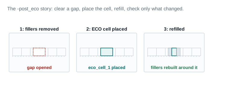
eco_cell_1 placed into that gap in green. Panel 3 shows the row refilled: two of the three original fillers return, and the third's site is now occupied by the real cell. With -post_eco, only that one real cell gets DRC-checked, not the whole row.| Fillers removed to open the gap | 3 |
|---|---|
| Fillers reinserted | 2 (1 site now occupied by the ECO cell) |
| Cells DRC-checked with -post_eco | 1 (the new cell) vs. all cells without it |
| Density before / after | 61.4% / 61.3% M1 (unchanged within rounding) |
What route_eco actually touches
route_eco routes only the nets an ECO created or modified — it does not rip up and reroute the block. Drawing that boundary explicitly is worth doing once, so “minimal” is visible instead of assumed.
route_eco blast radius
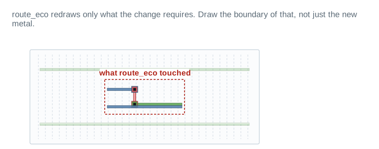
route_eco touched,” encloses only the small area where the ECO's new segments were drawn in solid M3 and M4. Everything outside that boundary is exactly as it was before the ECO.| Nets rerouted | 2 |
|---|---|
| Nets left untouched | 46 (same region, not shown faint beyond frame) |
| Vias added | 2 |
| DRC markers created | 0 |
Callback: chip finishing planted this for you
Chapter 6 signed off Nimbus‑8's density with a specific fill strategy: track-based fill on M2 through M7, pattern-based on M8 and M9, floating on M2 through M5, tied to VSS on M6 through M9. Every one of those decisions constrains what an ECO may do to fill near a change. Removing and rebuilding fillers with -post_eco respects that strategy by construction: it calls the same fill-generation logic Chapter 6 used, not a new rule for the ECO case.
The generic ECO flow, worked Verified
The four steps, applied to the worked ECO: one buffer insert on a u_sens_tile boundary net.
- 1Update the netlist:
add_bufferon the violating net (Part 4 covers the option family in full). - 2Place and legalize the new cell:
icc2_shell> place_eco_cells -eco_changed_cells \ -legalize_mode minimum_physical_impact \ -displacement_threshold 3.0 - 3Rebuild filler around the change only:
icc2_shell> create_stdcell_fillers -lib_cells {FILL1 FILL2 FILL4} \ -post_eco - 4Route the new and modified nets:
icc2_shell> route_eco
Before you fix anything, know exactly what is different
The first spine question is “what changed.” Answering it well, before you touch anything, is the single best habit this chapter teaches. eco_netlist is the command that answers it formally, by comparing your working design against a golden reference and writing the difference out as a file you can read before you run it.
Comparing against a golden reference
eco_netlist performs a name-based netlist comparison between the working design and a golden input, in one of two ways: -by_verilog_file against a golden Verilog file, or -by_block against a golden block. -golden_lib, -working_block and -working_lib say exactly which design and library each side comes from.
eco_netlist Verified
Comparing the working u_sens_tile against a golden block after the functional gate is added.
- 1Compare against the golden block and write the change file:
icc2_shell> eco_netlist -by_block golden_sens_tile \ -golden_lib nimbus8_golden_lib \ -working_block u_sens_tile -working_lib nimbus8_lib \ -write_changes sens_tile_eco.tcl - 2Read the file before you source it. This is the habit that separates a controlled ECO from an accident:
sens_tile_eco.tclis plain Tcl, and every line in it is a command you would recognize —create_cell,connect_net,change_link. Open it. Confirm it says what you expect. - 3Source it once you have confirmed it:
icc2_shell> source sens_tile_eco.tcl
By default, eco_netlist ignores some categories of difference not usually part of a functional ECO: physical-only cells, timing-ECO changes, and power/ground differences. -compare_physical_only_cells and -extract_timing_eco_changes turn that ignoring off — use them when your golden reference might predate a round of changes you want the comparison to see.
Netlist editing commands, for small changes
Not every change needs a golden reference and a formal comparison. For a small, well-understood edit — one gate, one connection — issue the netlist editing commands directly. create_cell instantiates a new cell from a library reference; connect_net and disconnect_net rewire pins; size_cell rebinds a cell to a different library variant (Part 4 covers this one in depth); and change_link swaps what a hierarchical instance points to.
Design-planning ECO scripts
Three commands from the design-planning flow generate ECO scripts for changes that are structural rather than purely logical — moving where a net lives in the hierarchy, or exposing spare capacity as real ports:
| Command | What it generates | Typical use |
|---|---|---|
write_ | A script that moves the branch-out of a multi-fanout net up to the top level | A net's fanout has outgrown its current hierarchical home |
write_ | A script that moves a tree of standard cells down from the top physical level into the overlapping blocks below | Logic was placed at the top level but logically belongs inside a block |
write_ | A script that creates dummy feedthrough ports on named cells for future use | Reserving port capacity ahead of an ECO you expect but have not designed yet |
write_push_down_eco Verified
Moving a cluster of top-level cells down into the block that overlaps them physically.
- 1Generate the push-down scripts, one per block, into a directory:
icc2_shell> write_push_down_eco [get_cells U0] -dir push_down_eco_scripts - 2Source the top block's script, which calls the others in the correct order:
icc2_shell> source ./push_down_eco_scripts/nimbus8_top.tcl
What this ECO actually is, inventoried
Once the delta is identified, write it down as a table before you place anything: cells added, removed, resized; buffers inserted; nets touched. Keep functional changes visibly separate from timing changes — Part 8 shows that separation is not optional once incremental signoff tracking is involved.
Every number here should trace to one line in the change file. If it does not, the inventory is wrong, not the change file.
| Item | Evidence | Source command / report | Threshold | Status | Required action |
|---|---|---|---|---|---|
| Cells added, removed, resized | |||||
| 1. Cells created (new instances) | 1 — eco_cell_1, a buffer | add_ | Matches change-file create_cell/add_buffer lines | PASS | — |
| 2. Cells resized | 1 — u_sens_tile/U88, upsized one drive strength | size_ | Matches change-file size_cell lines | PASS | — |
| 3. Cells removed | 0 | netlist diff | Matches change file (0 removals this ECO) | PASS | — |
| 4. Fillers displaced by the ECO | 3 removed, 2 reinserted (1 site now occupied) | create_ | Reconciles: removed = reinserted + occupied | PASS | — |
| Functional versus timing changes | |||||
| 5. Functional change (spec fix) | 1 — two-input AND gate added on the sensor-enable path | netlist edit, logged separately | Tracked apart from timing-only changes | PASS | — |
| 6. Timing-driven changes | 2 — the buffer insert and the upsize | fix_ | Tracked apart from the functional change | PASS | — |
| Nets touched | |||||
| 7. Nets split | 1 — the boundary net, split by the buffer insert | add_ | Matches change file | PASS | — |
| 8. Nets rerouted | 2 — the two segments of the split net | route_ | Matches Figure 14's blast-radius boundary | PASS | — |
| 9. Nets left untouched, same region | 46 of 48 nets in the local window | route_eco report | Untouched count matches the report | PASS | — |
Inventory verdict: 2 timing-driven changes, 1 functional change, 3 nets touched, 0 unaccounted → matches the change file exactly.
Read it: Row 5 is the one to notice: the functional change (a two-input gate for a spec fix) is tracked separately from the two timing changes, because Part 8 makes exactly this separation the line that stops incremental-signoff tracking.
Field values are this chapter's illustrative teaching data.
Three edits cover almost every ECO you will make
Once you know what changed, most ECOs come down to three kinds of edit: resize a cell, insert a buffer, or split an overloaded fanout. Figure 4 shows the worked ECO's buffer insert as real geometry. This Part gives you the three commands behind it, verified option by option.
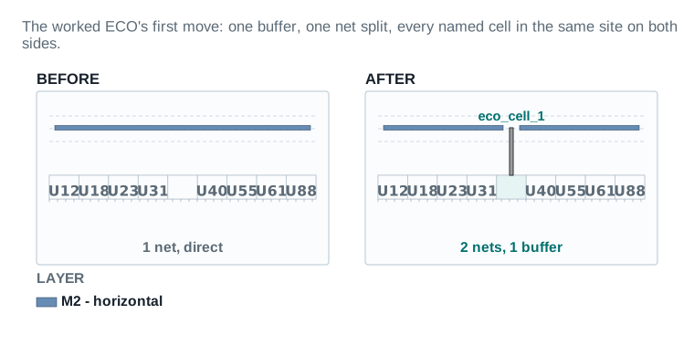
eco_cell_1, a buffer, is placed directly in that one free site, with a short pin connecting it up to the net: two shorter segments replace the one long one. ECO cell offset: 0 — zero neighbours displaced.| Cells added | 1 (eco_cell_1, a buffer) |
|---|---|
| Sites consumed | 1 (the site empty in both panels) |
| ECO cell offset | 0 µm — placed directly in the free site |
| Neighbours displaced | 0 |
| Wire length delta | +3.4 µm (illustrative) |
Resizing: size_cell
size_cell rebinds a leaf cell to a new library cell with a different drive strength, or other properties — the classic upsize-for-setup or downsize-for-power move. The cell being resized must already be in scope, at or below the current instance.
size_cell Verified
Upsizing u_sens_tile/U88, the second half of the worked ECO's timing fix.
- 1Rebind to a stronger drive-strength variant:
icc2_shell> size_cell u_sens_tile/U88 -lib_cell BUFX4_nimbus8_lib - 2Optionally bound how far the tool may search for a spare cell that could realize the resize instead of a fresh placement, or turn that search off entirely:
-max_distance_to_spare_cellor-not_spare_cell_aware.
Buffering: add_buffer and add_buffer_on_route
add_buffer adds a buffer cell on the nets connected to specified pins — the simple, pre-route form. add_buffer_on_route does the same thing on nets with real routed geometry, and carries the larger option family, because it has to decide where along the route the buffer lands.
add_buffer_on_route Verified
Splitting the boundary net at a physically sensible point along its real route.
- 1Insert on the violating net, letting the tool choose the split point:
icc2_shell> add_buffer_on_route [get_nets sens_ready_net] \ -lib_cell BUFX2_nimbus8_lib - 2Constrain the search along the route with
-max_distance_to_route,-repeater_distance,-first_distanceand-last_distance, and let the tool choose a legal site with-snap_to_sitesor an exact one with-location.-max_distance_for_incomplete_routebounds how far the buffer may sit from a route that has not finished detail routing. - 3Keep the new instance and net names predictable with
-cell_prefixand-net_prefix— the defaults areeco_cellandeco_net, exactly what Figure 5 shows on real geometry. - 4Choose whether the buffer may land over an existing cell with
-respect_blockages, and if so, which cells it may or may not land over with-allow_insertion_over_cellor-dont_allow_insertion_over_cell.
Splitting an overloaded fanout: split_fanout
Some violations are not about one net's routed length but about one driver serving too many loads. split_fanout reduces a driver's fanout by inserting a repeater cell, the standard fix for a max-fanout or max-capacitance violation that a single resize cannot clear.
split_fanout Verified
Reducing an overloaded driver's fanout by inserting one repeater cell.
- 1Select the driver, then bound the fanout:
icc2_shell> split_fanout -driver [get_pins u_sens_tile/U40/Z] \ -max_fanout 12 -lib_cell BUFX2_nimbus8_lib - 2
-driveror-netpick the target (mutually exclusive);-loads(plural) names the exact pins to move onto the new repeater instead of a fanout count, and is itself mutually exclusive with-max_fanout. - 3
-hierarchyand-on_routeare also mutually exclusive:-hierarchyadds a repeater on the loads crossing into a named hierarchy,-on_routebuffers by routing topology instead of logical connectivity. - 4The rest match
add_buffer_on_route's naming and placement-legality options:-respect_blockages,-max_distance_for_incomplete_route,-net_prefix,-cell_prefix, plus-same_net_connection_onlyto keep every moved load on the same original net.
Naming the results: -cell_prefix and -net_prefix
Every command in this Part that creates a cell defaults to a readable naming convention: new cells get the prefix eco_cell, new nets get eco_net, both followed by a running number. A cell an ECO resizes, by contrast, keeps its original instance name — size_cell rebinds a reference, it does not create a new instance.
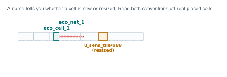
eco_cell_1 sits in teal in the row, with its net labelled eco_net_1 above the route leaving it — both new names, both from the default prefixes. To the right, the amber cell is labelled u_sens_tile/U88 (resized): the same instance name it had before the ECO, because size_cell changed what the instance is bound to, not what it is called.| New cell prefix | eco_cell (default) |
|---|---|
| New net prefix | eco_net (default) |
| Resized existing cell | keeps its original instance name |
Not every ECO is timing or DRC: a crosstalk fix
Some violations are neither a slack number nor a DRC rule — they are noise. A victim net running too close to a switching aggressor can pick up enough coupled delta delay to fail timing that would otherwise pass, and the fix is not a buffer or a resize but a shield.
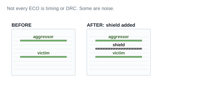
| Delta delay before shield | +22 ps (illustrative) |
|---|---|
| Delta delay after shield | +3 ps |
| Tracks consumed by the shield | 1 |
The ECO toolkit that starts before there is anything to fix
Every command in Parts 2 through 4 assumes there is somewhere for a new cell to go. Spare cells make that true ahead of time, planted by Chapter 6's chip-finishing pass and by floorplan design planning: the same discipline that set density is what plants spare capacity.
Three ways to get spare cells into a design
- Manual instantiation — place named spare-function instances by hand, the way you would place any other cell, when you know exactly what function you will need later.
add_spare_cells— inserts spare cells programmatically, from a named library cell reference and an instance count, or from a raw cell count.- Programmable spare cells via
create_stdcell_fillers— gate-array-style fillers that are not committed to one function until an ECO programs them.
add_spare_cells Verified
Inserting a batch of buffer-compatible spares across u_sens_tile.
- 1Name the batch and reference the library cell:
icc2_shell> add_spare_cells -cell_name sens_spare \ -lib_cell [get_lib_cells nimbus8_lib/BUFX2] -num_instances 24 - 2Scope where they go with
-hier_cell,-boundaryor-voltage_areas, and exclude blockage types they should not sit under with-ignore_blockage_types. - 3Choose the distribution:
-density_aware_ratiobiases spares toward where real cells already are;-random_distributionspreads them uniformly. Set how spare inputs are tied with-input_pin_connect_type tie_low | tie_high | open.
The four criteria that make a cell “spare”
The tool does not treat every idle-looking cell as a spare. A cell is recognized as spare when it meets all four of these:
- It is not a physical-only cell — a spare has a real logical function waiting to be used, unlike a filler or tap cell.
- All of its inputs, except a clock pin if it has one, are either unconnected or tied to a constant.
- Its output is unconnected.
- It is a real placed instance, occupying real sites, not a paper placeholder.
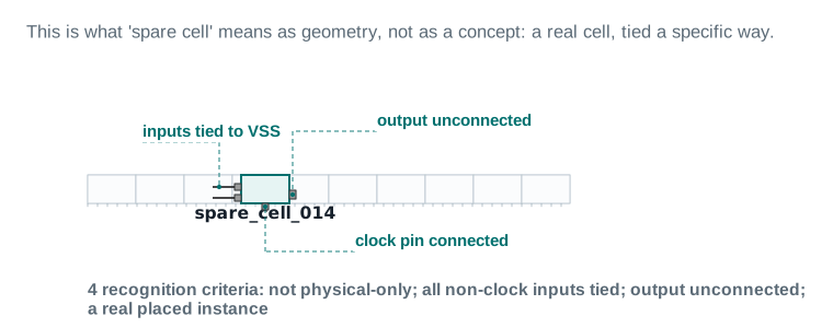
spare_cell_014 sits in the row like any other cell. Its two non-clock inputs are tied to VSS with a short metal stub. Its output pin has no wire leaving it at all. Its clock pin, if present, stays connected — a spare cell's function needs a live clock the moment it is mapped, so that connection is never the one left open.| Recognition criteria met | 4 of 4 |
|---|---|
| Inputs tied | 2 of 2, to VSS |
| Output | unconnected |
| Leakage cost of leaving it tied | 0.4 µW (illustrative) |
Distributing spares: spread_spare_cells
spread_spare_cells spreads spare cells — typically ones that arrived through a Verilog ECO or manual netlist editing, not yet placed — evenly across a rectilinear region, with the same distribution controls as add_spare_cells: -density_aware_ratio, -random_distribution, -boundary, -voltage_areas, -ignore_blockage_types.
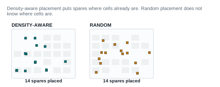
| Density-aware: spare count | 14 (this region, illustrative) |
|---|---|
| Density-aware: mean spacing | 38 µm |
| Random: mean spacing | 51 µm, higher variance |
| Coverage inside 50um of any cell cluster | density-aware 100% / random 71% |
Programmable spare cells: gate-array fillers
A fixed-function spare cell can only ever become the one function it was instantiated as. A programmable spare cell (PSC) is different: it is a gate-array-style filler shape that can be programmed, by metal and via connections alone, into any one of several compatible functions at ECO time. The psc_type_id attribute is what pairs a standard cell with the family of PSC shapes that can realize it — when you place a PSC, you are reserving a function family, not one fixed function.
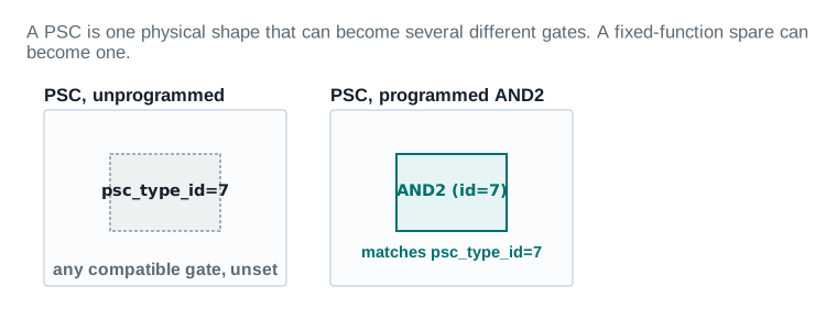
psc_type_id=7. The right panel shows the same physical shape after being programmed into an AND2 gate — a compatible function under the same id, realized entirely by the metal wiring drawn around it, not by any change to the shape itself.| Functions one PSC can realise | up to 4, by psc_type_id family |
|---|---|
| Functions a fixed-function spare can realise | 1 |
| Extra silicon area per PSC vs. fixed spare | ~1.15x (illustrative) |
The chip has taped out. Silicon is frozen. Metal is not.
Once a design has taped out, the diffusion, poly and contact layers exist in silicon, permanently. A freeze-silicon ECO is what you run when the fix must live entirely in metal and vias — rewiring already-manufactured transistors into a new function, never creating one.
Turning the mode on
design.eco_freeze_silicon_mode is the application option that tells ICC2 it is operating under this constraint. With it set, placement and legalization commands stop assuming they can create new silicon and start assuming every fix has to land on an existing spare.
Checking feasibility before you commit
check_freeze_silicon performs feasibility analysis on ECO-cell-to-spare-cell mapping for the current design, before you place anything. It takes no arguments — it reads the ECO cells and spare cells already present and reports whether a mapping is even possible.
check_freeze_silicon Verified
Confirming mapping feasibility before committing the worked ECO to a freeze-silicon flow.
- 1Set the mode:
icc2_shell> set_app_options -name design.eco_freeze_silicon_mode -value true - 2Check feasibility with no arguments:
icc2_shell> check_freeze_silicon - 3Read the report. A cell that comes back unmappable is a decision point, not an error to work around — see Figure 10.
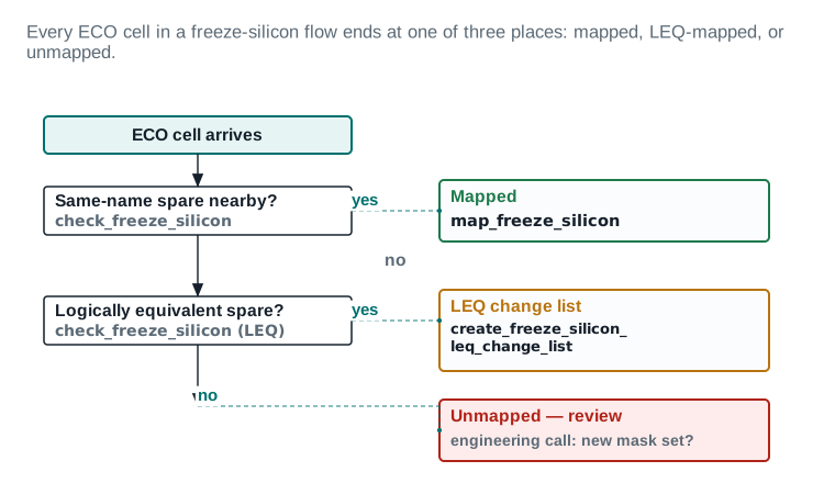
map_freeze_silicon maps it directly. If no, is there a logically equivalent spare — a different-named cell that computes the same function? If yes, create_freeze_silicon_leq_change_list builds a change list for it. If neither, the cell is unmapped, and the decision becomes an engineering call about a new mask set, not a tool command.Placing and mapping: place_freeze_silicon
place_freeze_silicon places new ECO cells by swapping out spare cells. Two options let you separate placement from mapping, which is the careful engineer's move: check QoR with cells placed near their targets before committing to which spare each one consumes.
place_freeze_silicon Verified
Trial-placing before committing, using -no_spare_cell_swapping to preview.
- 1Trial map, without swapping any spare cell yet:
This moves ECO cells to their targeted spare locations without committing the swap — a preview you can analyze and remap if the result looks wrong.icc2_shell> place_freeze_silicon -cells [get_cells eco_cell_1] \ -no_spare_cell_swapping -write_map_file trial_map.txt - 2Commit only the mapping decision, once you are satisfied:
-map_spare_cells_only. - 3Control how close a mapped cell may sit to a filler with
-min_filler_distance, and which PSC filler library cells recover unused white space between mapped cells with-lib_cells_for_filler_recovery.
Manual mapping: map_freeze_silicon
When you already know exactly which spare an ECO cell should become, map_freeze_silicon maps it directly: -eco_cell and -spare_cell name the pair, or -map_file reads a whole mapping from a file. -filler_map_strategy chooses how leftover white space packs once cells are mapped — pack_left, pack_right, pack_top, pack_bottom or closest. -advanced_nodes switches on additional rule checking appropriate to advanced process nodes, and can be paired with -skip_rule_check when that checking is not wanted for a specific call.
map_freeze_silicon Verified
Manually mapping the worked ECO's buffer onto a named spare.
- 1Map by name, with an explicit fill strategy:
icc2_shell> map_freeze_silicon -eco_cell eco_cell_1 \
  -spare_cell u_sens_tile/spare_cell_014 \
  -filler_map_strategy closest
The LEQ path, when no same-name spare exists
When the mapping decision in Figure 10 lands on “logically equivalent spare,” the command is create_freeze_silicon_leq_change_list. It writes a Tcl change list for ECO cells that need a logic-equivalence match rather than an exact same-name spare. The cells it operates on must be leaf cells with is_fs_eco_add true, and an eco_change_status of create_cell, add_buffer, add_buffer_on_route, change_link or size_cell.
create_freeze_silicon_leq_change_list Verified
Building and reading the LEQ change list, the same read-before-you-source discipline as Part 3.
- 1Write the change list:
icc2_shell> create_freeze_silicon_leq_change_list \ -cells [get_cells eco_cell_1] -output leq_changes.tcl - 2Read
leq_changes.tclbefore sourcing it, the same as any other ECO change file. - 3Source it once confirmed:
icc2_shell> source leq_changes.tcl
Rules for mapping onto PSCs
set_programmable_spare_cell_mapping_rule creates a mapping rule that governs how place_freeze_silicon is allowed to map onto programmable spare cells. -psc_type_id or -compatible select which PSC id families a rule applies to; further options control power-rail overlap behavior (-dont_overlap_pg_stripe_layer, -partial_overlap_pg_stripe_layer) and multi-height PSC handling (-multi_height_split, -multi_height_merge).
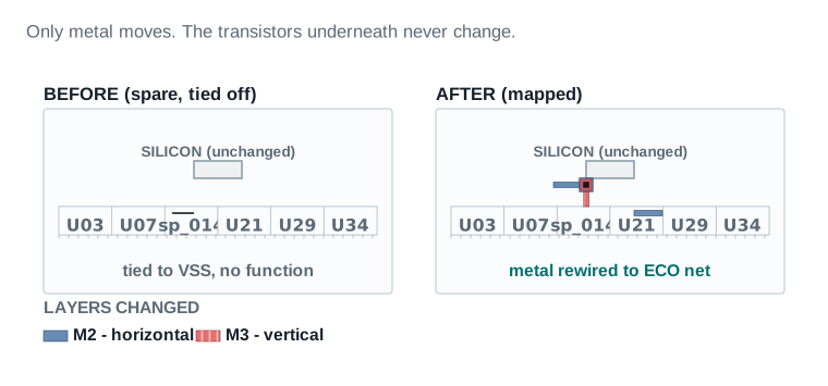
| Silicon (diffusion/poly) layers changed | 0 |
|---|---|
| Metal/via layers changed | M2, M3 only |
| Mask layers touched | 2 of the full mask set |
| Mask cost vs. a new tapeout | ~1 mask set vs. all layers |
This board would govern if the same ECO arrived after tapeout, when only metal may change. It is illustrative for that scenario, built on the same u_sens_tile numbers.
| Item | Evidence | Source command / report | Threshold | Status | Required action |
|---|---|---|---|---|---|
| Mapping outcome | |||||
| 1. ECO cells requiring mapping | 1 (the buffer insert) | check_ | — | PASS | — |
| 2. Mapped, same-name spare | 1 | map_ | — | PASS | — |
| 3. Mapped, LEQ change list | 0 | create_ | — | PASS | — |
| 4. Unmapped, requiring review | 0 | engineering review | 0 for this ECO to avoid a new mask set | PASS | — |
| PSC utilisation and mask layers | |||||
| 5. PSC utilisation, chip-level | 38% programmed, 62% headroom | PSC inventory | ≤ 70% programmed | PASS | — |
| 6. Mask layers touched | 2 (M2, M3 — metal and via only) | freeze-silicon change summary | 0 diffusion/poly layers touched | PASS | — |
Mapping verdict, freeze-silicon scenario: 1 of 1 ECO cells mapped same-name → 0 new mask layers required.
Read it: Row 1 is the whole story: because a same-name spare exists within the displacement budget, this ECO never needs the LEQ path (Figure 5's second branch) or an unmapped review (the third).
Field values are this chapter's illustrative teaching data; this board describes a freeze-silicon variant of the worked ECO, not the pre-tapeout flow used in Parts 2-5.
This is a two-tool chapter. Here is where the two tools hand off.
Signoff timing on Nimbus‑8 runs in PrimeTime, not ICC2. When PrimeTime's signoff analysis finds a violation — the worked ECO's −0.008 ns setup path on func_ss_0p72v_125c — the fix has to happen in PrimeTime too, because that is where the timing model lives. But the layout lives in ICC2. This Part is the loop that keeps both tools' pictures of the design true at once.
Shell discipline for this Part. Every command block below is marked with the shell it actually runs in. pt_shell> means PrimeTime. icc2_shell> means ICC2. Do not run a fix_eco_* command at an icc2_shell> prompt — it does not exist there.
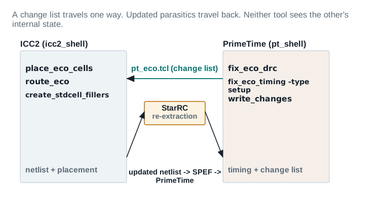
fix_eco_drc, fix_eco_timing, write_changes, and sends a change-list file, pt_eco.tcl, to ICC2. ICC2 runs place_eco_cells, route_eco, create_stdcell_fillers, and its updated netlist and placement go through StarRC for re-extraction, producing updated parasitics that flow back to PrimeTime. Neither tool ever reads the other's internal database directly — every arrow is a real file.The three PrimeTime fixing commands
The three core commands, all PrimeTime, all mandatory reading before you run your first signoff ECO:
fix_eco_drc PrimeTime
Fixing electrical-rule and noise violations, without regard to timing by default.
- 1Run at a
pt_shell>prompt:pt_shell> fix_eco_drc - 2It fixes max_transition, max_capacitance, max_fanout, static-noise, SI-bottleneck delta-delay and cell-electromigration violations by cell sizing and buffer or inverter-pair insertion.
- 3Crosstalk delta-delay fixing needs an explicit threshold, because there is no natural “delta-delay slack” to target automatically:
pt_shell> fix_eco_drc -type delta_delay -delta_delay_threshold 0.02
fix_eco_timing PrimeTime
Fixing the worked ECO's setup violation. The -type option is mandatory — there is no combined default.
- 1Fix setup, primarily by sizing (buffers are not inserted by default here, since more data-path delay is exactly what you do not want on a setup fix):
pt_shell> fix_eco_timing -type setup - 2Fix hold, by sizing and by inserting buffers or load cells (more delay is exactly what a hold fix needs):
pt_shell> fix_eco_timing -type hold - 3For a very small hold violation, prefer a dedicated load-capacitance cell over a buffer, using
-load_cell_list— see the sidebar below.
fix_eco_power PrimeTime
Recovering power and area on paths with slack to spare, without introducing new violations.
- 1Run with the default selection method, minimize area:
pt_shell> fix_eco_power - 2Downsizes on positive-setup-slack paths and removes buffers on positive-hold-slack paths — it spends margin the design already has, it does not create new margin.
Exporting the fix: write_changes
write_changes exports whatever fix_eco_drc, fix_eco_timing and fix_eco_power did as a Tcl change list, ready for ICC2 to source. pt_shell> write_changes -output pt_eco.tcl is the file Figure 12 shows crossing from PrimeTime to ICC2.
Logic-only versus physically aware
PrimeTime's ECO fixing can run in two modes. Logic-only works from the netlist and parasitics alone, with no placement awareness. Physically aware mode additionally reads real placement data, so fixes land only where physical room genuinely exists, and the change list records exact coordinates for fast, predictable implementation. Physically aware mode needs set_eco_options pointed at the design's physical data, and offers three placement strategies through -physical_mode:
| Value | Behavior | When to choose it |
|---|---|---|
occupied_ | Aggressive — may place or resize over existing neighbor cells, moving them later | Early-stage, high-utilization ECO where room is scarce |
open_ | Conservative — places only where room already exists, avoids moving existing cells | Late-stage, low-utilization ECO where minimal disturbance matters most |
freeze_ | Places changes only onto pre-placed programmable spare cells | Post-tapeout, when silicon may not change — the Part 6 flow |
A preview before committing: estimate_eco
estimate_eco gives a fast, approximate preview of a proposed size or buffer change's timing effect, before you pay for a full incremental update and a real report_timing re-evaluation — not exact, but fast enough to screen candidates before choosing one.
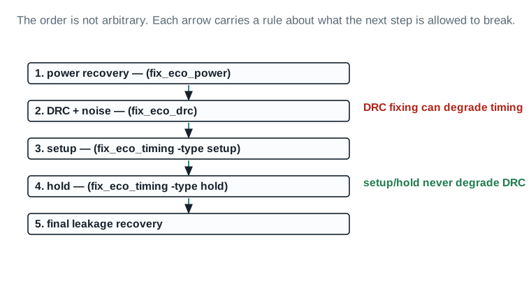
The fixing order, and why it is that order
Power recovery, then DRC and noise, then setup, then hold, then a final leakage-only power recovery — not arbitrary, but following directly from what each step is allowed to break.
The ICC2 side of the handoff
Once the change list arrives, ICC2's job is to source it and then place, fill and route exactly as the generic flow does, with one addition: legalization is explicitly told to minimize disturbance.
Sourcing a PrimeTime change list Verified
Applying pt_eco.tcl to the ICC2 design.
- 1Source the change list:
icc2_shell> source pt_eco.tcl - 2Legalize the changed cells, minimally:
icc2_shell> place_eco_cells -legalize_mode minimum_physical_impact \ -eco_changed_cells -legalize_only -displacement_threshold 10 - 3Rebuild filler and reroute, exactly as in Part 2:
create_stdcell_fillers -post_eco, thenroute_eco.
A single closing number hides whether the loop converged quickly or barely made it. This board keeps every iteration on the page.
| Item | Evidence | Source command / report | Threshold | Status | Required action |
|---|---|---|---|---|---|
| Iteration 1 (fix_eco_timing -type setup, then place/route) | |||||
1. WNS, func_, before fix | -0.008 ns | report_ | — | PASS | — |
2. WNS, func_, after fix + place/route | +0.004 ns | report_ | WNS ≥ 0 | PASS | — |
3. TNS, func_ | 0 ns | report_ | TNS = 0 | PASS | — |
| 4. DRC violations, this iteration | 0 | fix_ (not invoked, none present) | 0 | PASS | — |
| Iteration 2 (confirmation pass after re-extraction) | |||||
5. WNS, func_ | +0.004 ns (unchanged) | report_ | WNS ≥ 0, stable across iterations | PASS | — |
6. WNS, func_ | +0.017 ns (was +0.019 ns pre-ECO, the expected small hold shift) | report_ | WNS ≥ 0 | PASS | — |
| 7. Power delta | +0.6 µW dynamic (1 added buffer, illustrative) | check_ | ≤ 5 µW for a single-buffer ECO | PASS | — |
Loop verdict: converged in 2 iterations, both scenarios clean → signoff ECO loop closed.
Read it: Compare iteration 1 to iteration 2 on row 2: WNS moves from -0.008 ns to +0.004 ns in one pass, and DRC stays at 0 throughout, which is the fix-priority order (Figure 4) working as designed — DRC was never touched because it was never violated.
Field values are this chapter's illustrative teaching data.
The loop from Part 7 works. It does not always work cheaply enough.
A signoff ECO list is rarely one violation; it is often dozens, and running the full Part 7 loop — full extraction, full timing update — for each one is a schedule problem on a design Nimbus‑8's size. Incremental signoff ECO is the same loop, scoped to only what changed each time.
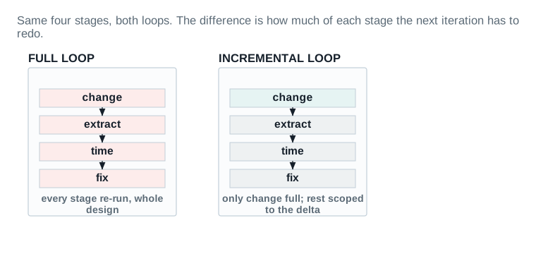
Recording, with a signature check: record_signoff_eco_changes
record_signoff_eco_changes records ECO changes for the incremental signoff flow across three calls: -start, an optional -init, and -stop.
record_signoff_eco_changes Verified
Recording the worked ECO's changes for incremental extraction.
- 1Start recording, checking the PrimeTime ECO Tcl file's signature against the current block before sourcing it:
If the signatures are inconsistent, or either side has no signature at all, the check fails and the command errors out — on success it automatically sources the file for you.icc2_shell> record_signoff_eco_changes -start -input pt_eco.tcl - 2Continue working — place, route, further PrimeTime timing ECO passes — while recording stays active.
- 3Stop recording and write the incremental design data, optionally in DEF form and compressed:
icc2_shell> record_signoff_eco_changes -stop -def -compress
Incremental extraction and incremental timing
Once record_signoff_eco_changes -stop has written the incremental design data, StarRC extracts only the changed portion of the design instead of the whole block, and PrimeTime updates timing incrementally against that partial extraction. A full-design extraction and analysis is reserved for the final signoff pass, not repeated on every intermediate iteration.
One command, both tools, no manual handoff
eco_opt is an ICC2 command that invokes PrimeTime timing and PrimeTime ECO under the hood, brings the changes back, and runs incremental place and route — the whole Part 7 loop, in one call. It is worth learning the manual loop first, in Parts 7 and 8, precisely so you can tell whether eco_opt did the right thing.
Setting up the PrimeTime connection: set_pt_options
Before eco_opt can invoke PrimeTime, ICC2 needs to know where PrimeTime lives and how to configure the session it starts. set_pt_options carries that configuration.
set_pt_options Verified
Pointing ECO Fusion at the PrimeTime executable and a pre-link setup script.
- 1Set the executable path:
icc2_shell> set_pt_options -pt_exec /tools/synopsys/primetime/bin/pt_shell - 2Add host distribution for parallel processing with
-host_option, and per-scenario constraint or script overrides with-scenario_scripts/-scenario_constraints. - 3Run setup before and after PrimeTime links the design with
-pre_link_scriptand-post_link_script, and let PrimeTime pick up its own local configuration from.synopsys_pt.setupin the working directory, exactly as it would in a standalone PrimeTime session.
StarRC inside the fusion flow
Extraction mode for the fusion flow is controlled by the extract.starrc_mode application option, defaulting to fusion_adv, with in-design and none as alternatives. set_starrc_options -config loads and validates a configuration file for running StarRC signoff extraction inside the PT ECO Fusion flow. The file names the StarXtract executable location, a corner-to-nxtgrd mapping file, a layer mapping file and a command file. -validate true checks that setup is correct before it is used.
The command itself: eco_opt
eco_opt optimizes the current routed design with PrimeTime timing and PrimeTime ECO. Run with no options, it defaults to fixing {setup hold drc total_power buffer_removal} — the full priority order from Part 7, in one call.
eco_opt Verified
Running the default fix set, then a preview-only run, on the worked ECO's block.
- 1Run with the default fixing types:
icc2_shell> eco_opt -types {setup hold} icc2_shell> check_pt_qor - 2Choose analysis effort with
-pba_mode none | path | exhaustive, the same graph-based-versus-path-based tradeoff covered in the PrimeTime User Guide. - 3Choose the physical strategy with
-physical_mode open_site | occupied_site— note thateco_opt's own list does not includefreeze_siliconthe wayfix_eco_timing's does; run a freeze-silicon ECO through the Part 6/7 manual path, not througheco_opt. - 4Preview without committing:
icc2_shell> eco_opt -types setup -write_change_file_onlywrites the PrimeTime ECO changes to a file instead of sourcing them — useful for review, but be aware the design status in ICC2 and in PrimeTime diverge until you do source it. - 5Supply a fully custom PrimeTime script instead of the built-in fix types with
-eco_script, which ignores-typesentirely when given.
Checking the result: check_pt_qor
check_pt_qor checks PrimeTime QoR — timing and power — against the current state. -type scopes the check to global_timing, summary, max_delay, min_delay, max_transition, max_capacitance, power or noise; -reset clears a prior baseline, and -report_script runs a custom reporting script.
The convergence warning: matching postroute settings
ECO Fusion's convenience depends on ICC2's postroute timing settings genuinely matching PrimeTime's. If they diverge, ECO Fusion will converge on a result that looks clean inside the fusion flow and disagrees with a standalone PrimeTime signoff run — which defeats the entire purpose of running signoff in PrimeTime in the first place.
check_consistency_settings Verified
Confirming ICC2's postroute settings agree with PrimeTime before trusting ECO Fusion's convergence.
- 1Compare against PrimeTime:
icc2_shell> check_consistency_settings -tool pt - 2Valid
-toolvalues arept,icc,icc2,pp/primepower,starrcandfusion_extraction— this command compares settings between ICC2 and any of PrimeTime, StarRC, PrimePower or IC Compiler, and also between Fusion extraction and StarRC in-design extraction. - 3Generate a correction script instead of applying changes silently:
-script fix_consistency.tcl, and review it before running-apply.
ECO Fusion power integrity
ECO Fusion extends past timing and DRC into voltage-drop-aware ECOs. rail.database is the application option pointing at a RedHawk-generated rail analysis database. analyze_rail -voltage_drop dynamic_vcd | dynamic_vectorless runs the drop analysis, and eco_opt -type power_integrity fixes what it finds — a fixing type that cannot be combined with the ordinary setup/hold/DRC types in the same call.
The heart of the chapter
place_eco_cells derives each ECO cell's placement from connectivity and delay, then legalizes it to the closest unoccupied site, leaving existing cells untouched by default. Every option this Part covers is a way of relaxing or tightening that default, and every one is a real trade between disturbing more and failing to place at all.
Choosing which cells to place
Three mutually exclusive ways to select the target cells: -cells names a specific collection; -unplaced_cells takes every cell with no location yet; -eco_changed_cells takes every cell whose eco_change_status attribute is create_cell, add_buffer, change_link, size_cell or add_buffer_on_route. That third option is exactly the set of edits Parts 3 and 4 taught you to make.
The three legalize modes, as a spectrum of disturbance
-legalize_mode takes one of three values, and the TCR's own description of each is worth reading verbatim, because it corrects a natural assumption: the default is not a fourth mode sitting alongside the other three. It is one of the three, named free_site_only.
| Mode | Behavior | Notes |
|---|---|---|
free_ (default) | Legalizes ECO cells on free sites only, without moving any other existing cell | Combine with -displacement_ to reject cells whose displacement would be too large rather than force a placement |
minimum_ | Tries free_ first; for any cell exceeding -displacement_, falls back to moving existing cells for just that cell | Requires -legalize_; the practical middle ground for most signoff ECOs |
allow_ | Legalizes every ECO cell on its nearest legal location, moving whatever existing cells are in the way | Cannot be combined with -displacement_ — there is no threshold to reject against, because moving cells is always allowed |
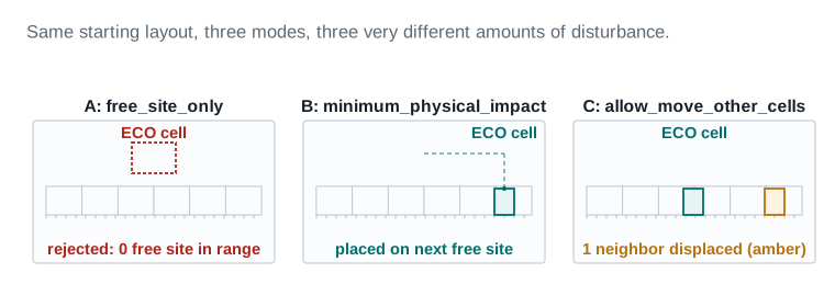
| A: default + threshold | 0 placed, 1 rejected (epl_legalizer_rejected_cells) |
|---|---|
| B: minimum_physical_impact | 1 placed, ECO cell offset 2.1 µm, 0 neighbours displaced |
| C: allow_move_other_cells | 1 placed, 1 neighbour displaced 0.6 µm |
Displacement thresholds, drawn as bands
-displacement_threshold sets the distance, in microns, beyond which the command will not legalize a cell — it keeps the cell's pre-legalization location instead and reports the rejected cell count. -max_displacement_threshold must be paired with it, and must be greater than or equal to it: it builds a collection, epl_max_displacement_cells, of ECO cells whose displacement exceeds even that outer band. That collection is a subset of the broader epl_legalizer_rejected_cells collection every rejected cell lands in.
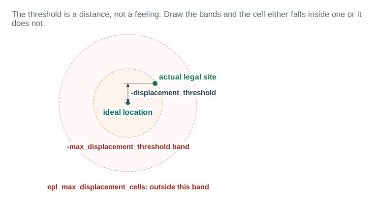
-displacement_threshold; the red band marks -max_displacement_threshold. The green dot is the actual legal site the tool found, dimensioned against the ideal location. Because that dot falls inside the amber band, the cell is placed, not rejected. A cell landing outside the red band would be added to epl_max_displacement_cells — not just rejected, but flagged as disruptive enough to reconsider the change itself.| ECO cell offset (ideal location to actual site) | 2.1 µm |
|---|---|
| -displacement_threshold | 3.0 µm (this ECO) |
| -max_displacement_threshold | 8.0 µm (this ECO) |
| Result | inside threshold — placed, not rejected |
Finding room before you need it: report_cell_feasible_space
report_cell_feasible_space reports feasible site spaces, scoped by -voltage_areas or -boundary, and can ignore specific filler references with -ignore_filler_references. Run it before committing to a change, to know whether the local neighborhood even has room, rather than discovering the answer from a rejected-cell report after the fact.
Shaping the coarse placement: net weight and virtual connections
Before legalization, place_eco_cells does a coarse, connectivity-based placement that decides roughly where each ECO cell should land. Three mechanisms let you shape that coarse placement:
-fixed_connection_net_weight— weights nets connected to a fixed point (an I/O pad or macro) more heavily, so the coarse placement pulls the ECO cell closer to that fixed point.-honor_user_net_weight, paired withset_eco_placement_net_weight -nets ... -weight ...(and inspected withreport_eco_placement_net_weight) — lets you set arbitrary per-net weights yourself before placement runs.-use_virtual_connection, paired withcreate_virtual_connection -name ... -pins ...— lets you define connections that do not exist in the real netlist, purely to bias the coarse placement, for cases where the real connectivity does not reflect the physical proximity you actually want.
All three support -channel_aware coarse placement, which additionally accounts for routing channels when deciding where an ECO cell should land.
place_eco_cells, the worked ECO's placement Verified
Legalizing the buffer insert with the middle-ground mode and a tolerance level.
- 1Place and legalize with the minimal-disturbance mode:
icc2_shell> place_eco_cells -eco_changed_cells \ -legalize_mode minimum_physical_impact -legalize_only \ -displacement_threshold 3.0 -max_displacement_threshold 8.0 \ -displacement_tolerance_level low - 2
-displacement_tolerance_level low | highis usable only with-legalize_mode minimum_physical_impact.lowis the default: prefer minimum displacement of the ECO cell itself, tolerating more movement of existing cells to get it.highreverses the preference: tolerate more ECO-cell displacement to keep existing cells still. Setting this option runsminimum_physical_impactwith the application optioneco.placement.optimized_legalizationset to true. - 3Bound how far the ripple of moved cells may extend with
-moveable_distance, usable only withminimum_physical_impactorallow_move_other_cells: only cells within this distance of an unlegalized ECO cell become movable at all.
Two more options round out the toolkit. -remove_filler_references tells legalization it may ignore and overlap unfixed filler cells of the named references, opening room without treating filler as an obstacle. And set_eco_placement_net_weight -reset clears any user net weights left over from a previous ECO, so they do not silently bias the next one.
The third spine question, answered with evidence
Parts 1 through 10 taught you how to make a minimal change. This Part is about proving, in numbers, that it stayed minimal. The commands here answer the chapter's third and final spine question directly.
Check before you place, not after: report_eco_physical_changes
report_eco_physical_changes reports the cell displacements and individual net-length changes resulting from size_cell, add_buffer and add_buffer_on_route. Run it before placement, on the change list you are about to source, not after placement has already happened. That ordering is deliberate: a report run after the fact can only tell you what already happened, while a report run before tells you what is about to.
report_eco_physical_changes Verified
Screening the change list for large displacement before committing to placement.
- 1Run before placement, filtered to changes above a minimum displacement worth reviewing:
icc2_shell> report_eco_physical_changes -min_displacement 2.0 - 2Scope to specific cells with
-cells, or by net-length ratio with-min_net_length_ratio, to find changes that will make a net disproportionately longer, not just displace a cell far. - 3Ignore filler references that are not real obstacles with
-ignore_filler_references, and group nearby ECO cells into clusters for review with-min_cluster_cell_distanceand-min_cell_number_in_cluster.
report_eco_physical_changes as a displacement histogram
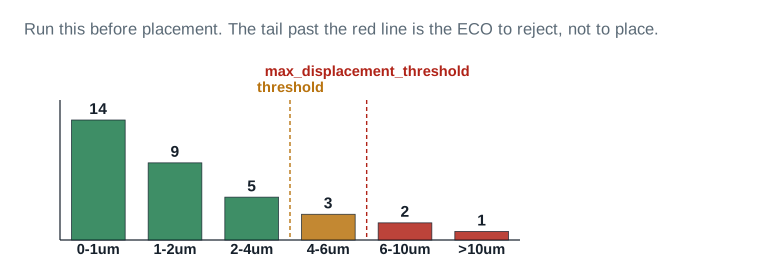
-displacement_threshold; the red dashed line marks -max_displacement_threshold. Every bar left of the amber line is a normal, expected placement. The two bars right of the red line, shaded red, are the ECO changes worth rejecting outright — not placing further out, rejecting.| Cells screened | 34 |
|---|---|
| Inside displacement_threshold (0-2µm) | 23 cells |
| Between the two thresholds (2-6µm) | 8 cells |
| Beyond max_displacement_threshold (>6µm) | 3 cells -- rejected, not placed |
Backing out a nonoptimal change: revert_eco_changes
revert_eco_changes -cells reverts ECO changes made by size_cell, add_buffer and add_buffer_on_route on the specified cells. Once report_eco_physical_changes or the displacement report from place_eco_cells itself flags a change as too costly, this is how you take it back cleanly, rather than hand-editing the netlist to undo it.
revert_eco_changes Verified
Backing out a buffer insert flagged by the displacement histogram as beyond the max threshold.
- 1Revert the flagged cells:
icc2_shell> revert_eco_changes -cells [get_cells eco_cell_7] - 2Re-derive the fix — a different buffer location, a load cell instead of a buffer, or a different legalize mode — and re-run
report_eco_physical_changesbefore placing again.
Keeping supply connections current: eco_update_supply_net
A buffer inserted by a timing ECO needs a real power and ground connection, and eco_update_supply_net is what keeps that connection current as ECO buffer trees grow. It covers cells added by add_buffer, add_eco_repeater, split_fanout and add_buffer_on_route — the same family of commands Part 4 taught. Left unspecified, -cells defaults to updating every cell any timing ECO command has added; specified, it updates just the named cells and the “ECO buffer tree” connected to them — a group of connected timing-ECO cells, bounded by any cell of a different type.
Recording exact layout changes: record_layout_editing
record_layout_editing records changes to the layout for a restricted set of objects and writes them to a Tcl script file. It is specifically documented as a command for final tapeout DRC fixing, not general ECO placement — which is why it belongs in this Part's evidence toolkit rather than earlier ones.
record_layout_editing Verified
The parallel-editing workflow: record a bounded shape edit and hand the result to a reviewer.
- 1Start recording:
icc2_shell> record_layout_editing -start - 2Make the edit — for instance, a manual shape fix for a final-tapeout DRC violation:
icc2_shell> remove_shapes RECT_32_0 - 3Stop and write the changes:
icc2_shell> record_layout_editing -stop -output change.tcl
The worked ECO, followed end to end
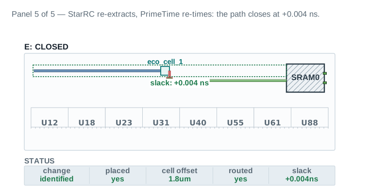
Every number this Part has introduced — identified, placed, cell offset, routed, slack — is a column in the same status strip, tracked across one region through the whole lifecycle of the worked ECO from Part 1. Five panels, same coordinate frame, same u_sens_tile boundary and the same SRAM0 macro in every one, so the only thing that changes panel to panel is the thing the caption says changed. Read the five status strips left to right and you are reading the chapter's whole spine acted out on one net.
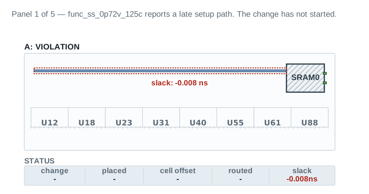
func_ss_0p72v_125c reports a late setup path at −0.008 ns, outlined in red. Nothing has been touched yet — every status-strip column reads a dash except slack.| Scenario | func_ss_0p72v_125c |
|---|---|
| Slack | -0.008 ns |
| Change / placed / cell offset / routed | - / - / - / - |
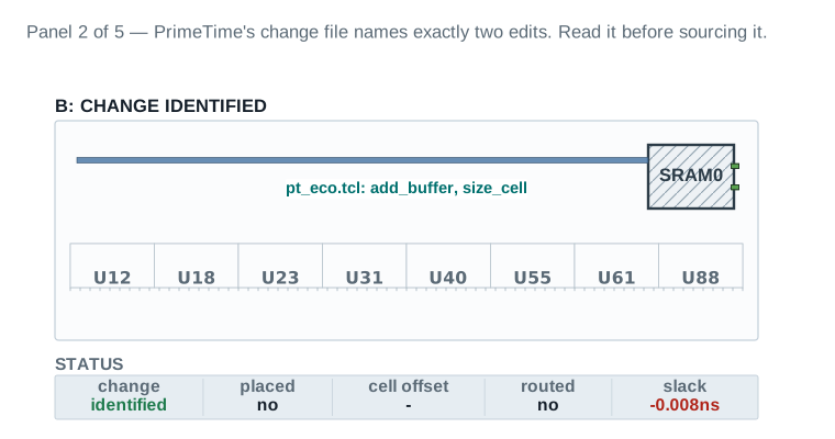
pt_eco.tcl, names exactly two edits — add_buffer and size_cell — identified, and read, before either is applied. Slack is unchanged.| Change file | pt_eco.tcl: add_buffer, size_cell |
|---|---|
| Placed / cell offset / routed | no / - / no |
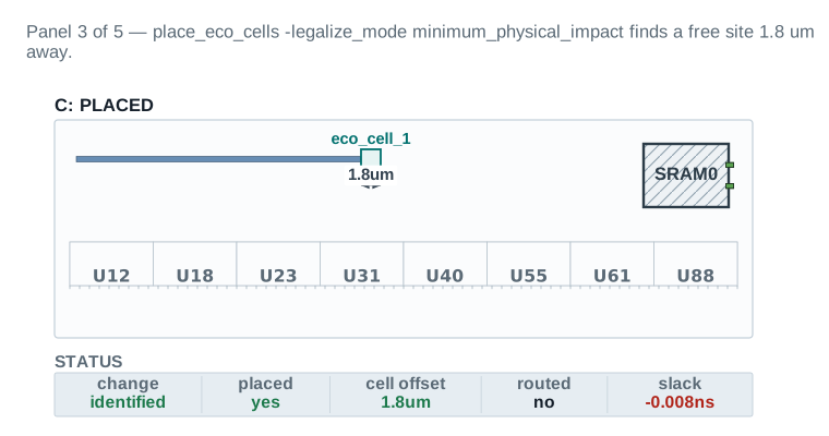
place_eco_cells -legalize_mode minimum_physical_impact finds a free site 1.8 µm away and legalizes the buffer there, dimensioned on the drawing. Still pre-route; slack unchanged.| Legalize mode | minimum_physical_impact |
|---|---|
| ECO cell offset | 1.8 µm |
| Neighbours displaced | 0 |
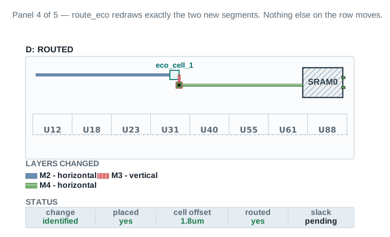
route_eco redraws exactly the two new segments, in M3 and M4, that the buffer split the original net into. Nothing else on the row moves. Slack is pending re-time.| Nets rerouted | 1, into 2 segments |
|---|---|
| Vias added | 1 |
| Final slack | +0.004 ns, func_ss_0p72v_125c |
|---|---|
| Total ECO cell offset | 1.8 µm (1 cell) |
| Neighbours displaced | 0 |
The evidence set: what a clean ECO looks like in numbers
Bring every number this Part produces together, and a clean ECO has a specific shape: displacement inside the threshold band, zero rejected cells, supply nets current on every new buffer, and a layout-editing record that lets a later engineer reconstruct exactly what happened. Dashboard 5, the blast radius board, is this Part's numbers assembled into one table.
This is the board that answers the chapter's second spine question directly: how little did this ECO disturb?
| Item | Evidence | Source command / report | Threshold | Status | Required action |
|---|---|---|---|---|---|
| Displacement | |||||
| 1. ECO cells placed off their ideal location | 1 (eco_cell_1's legalized site vs. its ideal location) | report_ | ≤ 5 cells for a single-buffer ECO | PASS | — |
| 2. Max ECO cell offset | 1.8 µm | report_ | ≤ 8.0 µm (max_displacement_threshold) | PASS | — |
| 2b. Neighbours displaced | 0 (minimum_physical_impact found a free site; no existing cell was pushed aside) | report_ | 0 under minimum_physical_impact / free_site_only | PASS | — |
| 3. Cells rejected by legalization | 0 (epl_legalizer_rejected_cells empty) | place_ | 0 rejected on the first placement attempt | PASS | — |
| Fill and density | |||||
| 4. Fillers removed to open room | 3 | create_ | Reinserted count + occupied count reconciles | PASS | — |
| 5. Fillers reinserted | 2 | create_ | — | PASS | — |
| 6. Density delta, local window | M1 61.4% → 61.3% (within rounding of Chapter 6's finishing exit value) | density window report | ≤ 0.5 point delta, local window | PASS | — |
| Routing and DRC | |||||
| 7. DRC markers created by the ECO | 0 | route_ | 0 new markers | PASS | — |
Blast-radius verdict: 8 of 8 rows inside budget → this ECO is minimal by every measure recorded here.
Read it: Row 2, max ECO cell offset, is the number to defend in review: 1.8 µm against an 8.0 µm max_displacement_threshold — that is how far eco_cell_1 itself landed from its ideal location, not how many other cells moved. Row 2b makes the second number explicit: 0 existing cells were pushed aside to make room for it. Row 6, density delta, shows chip-finishing's fill discipline survived the ECO untouched, which is the callback Part 5 promised.
Field values are this chapter's illustrative teaching data.
The closure gate for an ECO, and for the series
This Part closes two things at once: the worked ECO, and the eight-chapter guide it was chosen to demonstrate. Both close against the same gate, because an ECO's closure criteria are, in miniature, the same criteria the whole guide has been building toward since Chapter 1.
The closure gate for an ECO
- Timing re-verified on both scenarios. Not just the scenario that found the violation —
func_ss_0p72v_125candfunc_ff_0p88v_m40cboth, because a setup fix can shift hold, as Part 7's small-hold-violation lesson already warned. - DRC clean. The fixing order in Part 7 guarantees setup and hold fixes cannot reopen DRC — confirm that guarantee held, do not just assume it.
- Density unchanged. Chapter 6's signed-off fill and density windows, re-checked after the ECO's filler rebuild.
- Displacement inside budget. Every number Dashboard 5 tracked, still inside the thresholds set before placement.
- Change list archived. The PrimeTime change file, the layout-editing record, and the readiness and inventory dashboards, all kept together as one ECO record.
Every other board in this chapter feeds this one. This is the board a reviewer who has ten minutes should read, and the one that closes the series.
| Item | Evidence | Source command / report | Threshold | Status | Required action |
|---|---|---|---|---|---|
| Timing and DRC | |||||
1. Timing clean, func_ | WNS +0.004 ns, TNS 0 ns | report_ | WNS ≥ 0, TNS = 0 | PASS | — |
2. Timing clean, func_ | WNS +0.017 ns, TNS 0 ns | report_ | WNS ≥ 0, TNS = 0 | PASS | — |
| 3. DRC clean | 0 violations | fix_ report / route_eco DRC pass | 0 violations | PASS | — |
| Density, displacement, evidence archived | |||||
| 4. Density within signoff | M1 61.3%, within Chapter 6's signed-off band | density window report | Within Chapter 6's exit band | PASS | — |
| 5. Displacement within budget | max 1.8 µm of 8.0 µm budget | Dashboard 5 | ≤ budget | PASS | Dashboard 5 record |
| 6. Change list archived | pt_eco.tcl, reviewed and stored | write_ | Stored with the ECO record | PASS | pt_eco.tcl, archived |
| 7. Layout-editing record archived | record_layout_editing output stored alongside the change list | record_ | Stored with the ECO record | PASS | layout-editing.tcl, archived |
| Checkpoint and series close | |||||
| 8. Checkpoint saved | nimbus8_ | save_ | Exists and reopens clean | PASS | nimbus8_ |
| 9. Checkpoint confirmed to reopen | Reopened, 0 errors, timing matches archived values | checkpoint reopen test | 0 errors, timing matches | PASS | reopen log |
| 10. Series handoff note written | What the eight-chapter guide taught end to end, floorplan through ECO Flow | handoff review | Present | PASS | Part 12 close, this chapter |
Stage-exit verdict: 10 PASS, 0 REVIEW, 0 BLOCKER → GO. This ECO, and the eight-chapter guide it closes, are done.
Read it: Every row names the saved artifact that proves it. Row 9, the layout-editing record, is what lets a later engineer reconstruct exactly what changed and why without re-running the ECO.
Field values are this chapter's illustrative teaching data.
What the reader now knows, end to end
Eight chapters ago, this guide started with an empty library and a netlist. Floorplan shaped that netlist. Placement and optimization filled it with legally placed cells. Clock tree synthesis gave those cells a trustworthy clock. Routing and postroute optimization connected everything with real, rule-clean metal. Chip finishing and design for manufacturing made that metal signoff-clean and manufacturable. Hierarchical implementation showed how to do all of that at a scale too large for one flat run. And this chapter, ECO Flow, is what you do the day after all of that is declared done and something still needs to change.
That last sentence is the whole point of this being the final chapter and not an appendix. Every fact this chapter used, it borrowed from somewhere earlier: placement legality from Chapter 4 is what makes place_eco_cells's legalize modes meaningful. The clock trees Chapter 5 built are what Part 9's clock-network ECO fixing is careful not to disturb. The routing rules Chapter 6 signed off are what route_eco's blast radius in Figure 3 respects. The fill and spare cells Chapter 6's chip-finishing planted are what Part 5's cost ledger reconciles against, cell for cell. And the block boundaries Chapter 7's hierarchical implementation drew are the constraint a freeze-silicon or signoff ECO on a partitioned design must respect.
A reader who has followed this guide from Chapter 1 to here has built a chip and repaired it, in that order, with the same vocabulary and the same discipline throughout. That is what “end to end” means for this series, and this Part is where it closes.
45 questions, tiered, every answer grounded in this chapter
Forty-five questions across four tiers: 16 beginner, 15 intermediate, 9 advanced, and 5 senior/architect (16+15+9+5 = 45). Every answer draws only on what this chapter taught; illustrative numbers are labelled as such, and no command appears in an answer that was not verified in the body text. At least six questions cross back to earlier chapters, marked ↩ earlier chapter.
Beginner, 16 questions
- 1. What is an ECO?
- An incremental change to a complete or nearly complete design, used to fix functional, timing, noise and crosstalk violations without re-synthesizing, re-placing and re-routing the whole design.
- 2. What is a spare cell?
- A real, placed cell that is recognized as available for future use: it is not physical-only, all of its non-clock inputs are tied or unconnected, and its output is unconnected. It has a real logical function waiting to be wired in.
- 3. What does “freeze silicon” mean?
- A constraint, active after tapeout, under which the diffusion, poly and contact layers may not change at all — only metal and via layers may. A freeze-silicon ECO realizes its fix entirely by rewiring existing, already-manufactured transistors.
- 4. Which command places ECO cells?
place_eco_cells. It performs coarse placement from connectivity, then legalizes to the closest unoccupied site.- 5. What does
-post_ecosave, oncreate_stdcell_fillers? - It scopes the filler DRC check to only the cells the ECO placed, instead of checking every filler cell in the design, which saves real runtime on a large design.
- 6. Name the five ECO flows.
- Generic ECO flow, freeze silicon ECO, signoff ECO, incremental signoff ECO, and ECO Fusion.
- 7. What is the first question that decides which flow you are in?
- What are you still allowed to change — silicon and metal, or metal only — and whether the design has taped out at all.
- 8. Which command compares a working design against a golden reference?
eco_netlist, using either-by_verilog_fileor-by_block.- 9. What is
eco_cellandeco_net? - The default name prefixes
add_bufferandadd_buffer_on_routeuse for new cells and new nets they create. - 10. What are the three legalize modes for
place_eco_cells? free_site_only(the default),allow_move_other_cells, andminimum_physical_impact.- 11. What is a displacement threshold?
- A distance, in microns, beyond which
place_eco_cellswill not legalize a cell — it keeps the cell at its pre-legalization location instead, and reports it as rejected. - 12. Which PrimeTime command exports an ECO's changes for ICC2 to apply?
write_changes.- 13. What does
fix_eco_timing's-typeoption require? - It is mandatory: you must specify
setuporhold. There is no combined default that fixes both at once. - 14. What is a programmable spare cell (PSC)?
- A gate-array-style filler shape that can be programmed, by metal and via wiring alone, into one of several compatible functions at ECO time, rather than being committed to a single fixed function the way an ordinary spare cell is.
- 15. Which shell does
fix_eco_drcrun in? - PrimeTime's
pt_shell, not ICC2'sicc2_shell. - 16. What is the worked ECO used throughout this chapter?
- A late setup violation on a
u_sens_tileboundary path, fixed with one buffer insert (eco_cell_1) and one cell upsize (u_sens_tile/U88), alongside a small functional change adding a two-input gate.
Intermediate, 15 questions
- 17. Why does
place_eco_cellsleave existing cells untouched by default? - Its default legalize mode,
free_site_only, is built for minimal disturbance: it places ECO cells on free sites and never moves anything else, on the theory that the cheapest ECO is one that changes nothing beyond what it strictly needs to. - 18. What is in a change file, and why read it before sourcing it?
- Plain Tcl — ordinary netlist editing commands like
create_cell,connect_net,change_link. Reading it before sourcing is the single best habit this chapter teaches: it is the only way to confirm the change matches what you expect before it is applied to the design. - 19. Why must you tie a spare cell's inputs to a rail?
- A floating CMOS input is not electrically inert — it can drift near the switching threshold, causing leakage current and, under noise, oscillation. Tying unused inputs to a defined rail keeps an unmapped spare quiet until it is mapped.
- 20. What stops incremental signoff ECO tracking?
- A functional ECO change. Additional timing ECO changes may continue while
record_signoff_eco_changesis active, but a functional change ends the recording session. - 21. Why is
-respect_blockagesnot the default onadd_buffer_on_route? - Because respecting every blockage can push the search much further from the net's real route, making the wire longer instead of shorter. It trades placement legality against displacement distance, and the default leaves that trade to the engineer.
- 22. What happens to a cell a freeze-silicon ECO “deletes”?
- It is not removed from the design — silicon cannot be removed after tapeout. It is retired back to spare status and stays in the design, tied off, available for a future ECO.
- 23. What is the difference between logic-only and physically aware PrimeTime ECO fixing?
- Logic-only works from netlist and parasitics alone, with no placement awareness. Physically aware mode reads real placement data, so fixes land only where physical room genuinely exists, and the change list records exact coordinates.
- 24. Why is
-max_displacement_thresholddifferent from-displacement_threshold? -displacement_thresholddecides what gets legalized versus rejected.-max_displacement_thresholdbuilds a separate collection,epl_max_displacement_cells, of changes disruptive enough that the right response may be rejecting the ECO change itself, not just its placement.- 25. What does
-post_ecoactually change about howcreate_stdcell_fillersruns? - It scopes the DRC check step to the ECO-placed cells only, leaving the rest of the design's fillers unchecked because nothing about them changed.
- 26. Why must
eco_netlist -write_changesor-write_changes_per_modulebe specified? - The command requires exactly one of them: they are how the comparison result gets written out at all, and they are mutually exclusive because they represent two different output shapes — one combined file versus one file per module with a dependency-ordered source sequence.
- 27. What is a “buffer tree” in the context of
eco_update_supply_net? - A group of connected timing-ECO cells — added by
add_buffer,add_eco_repeater,split_fanoutoradd_buffer_on_route— bounded by any cell of a different type, treated as one unit when supply-net connections are updated. - 28. Why does
-displacement_tolerance_level hightolerate more ECO-cell displacement? - Because it inverts the usual preference. Instead of minimizing how far the ECO cell itself moves, at the cost of moving more existing cells to make room, it minimizes how much existing cells move — even if the ECO cell lands further from its ideal location.
- 29. What is the difference between a filler cell and a spare cell?
- A filler cell has no logical function — it exists to keep a standard-cell row continuous and hold density. A spare cell has a real function, simply unused, its inputs tied off until an ECO maps it. Neither is ever selected as an ECO target cell.
- 30. Why does
fix_eco_power's default selection method minimize area rather than power directly? - Because minimizing measured power requires PrimePower data from
update_powerfirst, via-power_mode; area minimization needs no such prerequisite and is available immediately, which is why it is the default rather than the more precise but more setup-dependent power-mode option. - 31. Why does editing an instance inside a multiply instantiated block uniquify it?
- So the edit applies only to that one instance's behavior, not to every sibling instance of the same module. The tool creates a private copy of the module, and its ancestors up to the first singly instanced level, specifically to contain the change.
Advanced, 9 questions
- 32. When do you choose
minimum_physical_impactoverallow_move_other_cells? - Choose
minimum_physical_impactwhenever a free site exists close enough to be acceptable — it tries free-site placement first and only falls back for the cells that need it. Reach forallow_move_other_cellsonly when the design genuinely has no room and failing to place is the worse outcome; it always succeeds, but every cell it moves is a disturbance you did not intend. - 33. Why is the fix order power → DRC → setup → hold → leakage?
- Because DRC fixing is allowed to degrade timing, while setup and hold fixing are guaranteed never to degrade DRC. Fixing DRC before timing means a later timing fix cannot silently reopen a DRC violation you already closed; reversing the order risks exactly that.
- 34. When is a load-capacitance cell the right hold fix instead of a buffer?
- For a very small hold violation, on the order of five picoseconds or less. A buffer adds a full logic stage of delay, which typically over-fixes a violation that small and can turn it into a new setup violation on the same path. A load cell adds just enough capacitance without adding a stage.
- 35. When do you reject an ECO change rather than the placement?
- When
report_eco_physical_changes, before placement, orepl_max_displacement_cellsafter it, shows a displacement so large it is telling you something about the change itself, not just this placement attempt. At that point,revert_eco_changesand re-deriving the fix is the right move, not tuning the legalize mode further. - 36. Why can't
-displacement_thresholdbe combined with-legalize_mode allow_move_other_cells? - Because
allow_move_other_cellsis defined to always find a legal location by moving whatever is in the way — there is no concept of “too far, so reject it” in that mode, since the mode's entire purpose is to never reject. A threshold has nothing to check against. - 37. Why does ECO Fusion need
check_consistency_settingsspecifically, and not just a cleaneco_optrun? - Because ECO Fusion's convenience depends on ICC2's postroute timing settings genuinely matching PrimeTime's. A clean
eco_optrun only proves the fusion flow's own view is self-consistent, not that it matches a standalone PrimeTime signoff run, which is the actual signoff authority. - 38. Why does the LEQ path exist, if same-name spare mapping is simpler?
- Because a same-name spare of the exact cell type is not always nearby, but a different-named cell computing the same logical function often is.
create_freeze_silicon_leq_change_listlets a freeze-silicon ECO succeed without an exact type match, at the cost of an extra generation step. - 39. What makes a PSC reduce mask cost compared to a fixed-function spare?
- A PSC's transistor-level shape is fixed at tapeout, same as any other cell; only the metal and via layers above it change when it is programmed. That metal-only change is exactly what a freeze-silicon ECO can make without a new mask set; a different fixed-function spare's silicon might force one.
- 40. Why is
eco.placement.optimized_legalizationrelevant even if you never set it directly? - Because setting
-displacement_tolerance_levelonplace_eco_cellsforces this application option totrueregardless of its prior value. A change made through one command's option can silently change a different command's default behavior later in the same session — which is why this chapter's command-verification discipline checks the full argument description, not just the option's name.
Senior / architect, 5 questions
- 41. How do you decide between a freeze-silicon ECO and a new mask set?
- Run
check_freeze_siliconfirst: if every ECO cell maps, same-name or by logic equivalence, the freeze-silicon path is almost always cheaper than a new mask set. The decision tips toward a new mask set when a meaningful fraction of cells come back unmapped — an engineering and cost decision, not a tool command. - 42. Who owns the decision that an ECO is too disruptive?
- The person who receives the
epl_max_displacement_cellsreport should not unilaterally push through withallow_move_other_cells. That decision belongs to whoever owns the schedule and physical-verification risk for the block — a disruptive change deserves design-review visibility, not a placement-option choice made alone at a terminal. - 43. How do you keep a signoff ECO loop from iterating forever?
- Fix in the documented priority order every time, so earlier steps cannot be silently reopened later. Use
estimate_ecoto screen candidates before a full incremental update, and track convergence explicitly — Dashboard 4's iteration-by-iteration WNS and TNS shows whether the loop is closing or oscillating, not just one final number. - 44. What do you archive so a later engineer can reconstruct what this ECO did and why?
- The PrimeTime change file (
pt_eco.tcl), the layout-editing record fromrecord_layout_editing -stop -output, the readiness and change-inventory dashboards from before the ECO started, and the blast-radius numbers from after. Together these let a later engineer reconstruct not just what changed, but why it was judged acceptable at the time. - 45. What did this chapter, and this guide, teach end to end?
- The guide taught how to build a chip: floorplan shapes it, placement and optimization fills it, clock tree synthesis gives it a trustworthy clock, routing and postroute optimization connects it, chip finishing makes it manufacturable, and hierarchical implementation shows how to do all of that at a scale too large for one flat run. This chapter taught what happens the day after that is declared done and something still has to change, using a fact one of the earlier chapters established at every step. Building and repairing a chip, in this guide, were never two separate skills.
Cross-chapter questions, gathered
Six questions above cross back to earlier chapters explicitly. Q19 depends on Chapter 6's chip-finishing fill discipline for why tied inputs matter electrically. Q29 depends on the filler/spare distinction Chapter 6 established during density signoff. Q32 and Q35 depend on the placement-legality vocabulary Chapter 4 built. Q41 depends on the block-boundary constraints Chapter 7's hierarchical implementation drew. And Q45 depends on all seven chapters at once, by design, as this chapter's closing question.