Detailed Design Analysis
Hierarchical Implementation in ICC2: A Mentor Guide
How a design too large to hold in one placement database gets cut into blocks, closed in parallel, and reassembled, partitioning, pin assignment, feedthroughs, timing budgeting, abstract views, ETMs, and top-level closure, taught from zero, the way a senior engineer would explain it to a new hire at their desk.
Why a finished, manufacturable design still needs this chapter
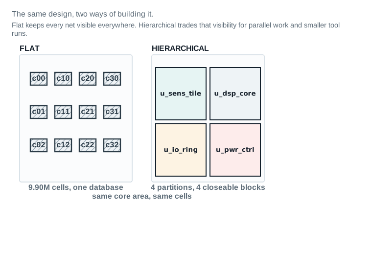
Picture a construction site big enough that no single supervisor can walk the whole thing in a day. The company does not hand one person the entire blueprint and a hard hat. It splits the site into zones, gives each zone its own foreman, its own crew and its own daily target, and agrees in advance exactly where each zone's walls meet its neighbour's. Nimbus‑8, at 9.90 million standard cells and 73 macros, is that site. Chapters 1 through 6 of this guide implemented a single zone, the u_sens_tile sensor partition, as if it were the whole chip. This chapter is about the rest of the site: how the whole thing gets divided, how the zones agree on their shared walls, and how the pieces come back together into one building that a foundry can pour.
A beginner arriving here usually assumes hierarchy is an optimization, something you turn on for a big design the way you might turn on multithreading. That is close, but it understates the cost. Hierarchy is a trade. You get parallel work and a tool run that finishes overnight instead of never. You pay for it in a permanent gap between what each block's model claims and what the real block does. This chapter's whole job is teaching you to see that gap, measure it, and keep it small enough that it never surprises you at the end.
What this chapter covers, in the order you will use it
The order matters and it is not arbitrary. You partition the design before you shape the blocks, because shape depends on what is inside each partition. You shape and assign pins before you write a timing budget, because a budget is a number attached to a real pin at a real location, not an abstract promise. You budget before you build an abstract, because an abstract's job is to prove the budget is achievable. And you do all of that before top-level closure, because closure is the step that checks whether every promise the earlier steps made turned out to be true. By the end of this chapter you will be able to decide how to partition a design and defend the decision. You will assign pins and push feedthroughs through a block correctly, and split and rebudget timing across a boundary. You will choose between an abstract, a frame and an ETM with reasons. You will run top-level closure, read why it failed when every block passed, and hand a closed hierarchical design to the next stage with a defined exit state.
| What enters this stage | What must leave it |
|---|---|
| A fixed Nimbus‑8 netlist, elaborated and linked, with 0 unresolved references (Part 3, Dashboard 1). | A defined partition set: every block named, sized and bounded, with its cell count and area reconciled to the Nimbus‑8 totals (Part 4). |
| Chip-level SDC and UPF, complete and checked (Part 3). | Every block's pins assigned at real pitch, on legal layers, with feedthroughs pushed down and accounted for (Part 5). |
| A fixed 3.20 × 3.20 mm core floorplan and a full macro inventory (Part 3). | A timing budget on every boundary-crossing path, split and later rebudgeted (Part 6). |
The u_sens_tile partition, already closed at block level in Chapters 5–6, as a fixed sub-block of the whole. | A top-level model, abstract, frame or ETM, chosen per block with its accuracy measured, not assumed (Parts 7–8). |
| A design planning flow available for hierarchical use (design planning UG Ch 1). | A top level closed on real timing, in every scenario, with the reason recorded if any block ever needed a second pass (Part 9). |
| — | A saved, reopenable top-level checkpoint and a written exit state for ECO Flow (Part 12). |
u_sens_tile, u_dsp_core, u_io_ring and u_pwr_ctrl, each with a heavy boundary, each closeable on its own. The core area and the total cell count are identical on both sides; only the organisation changes.| Runtime, one placement pass | flat: ~14 h | hierarchical block: ~50 min |
|---|---|
| Peak memory | flat: ~48 GB | hierarchical block: ~4 GB |
| Team parallelism | flat: 1 engineer | hierarchical: 4 blocks in parallel |
| Interface accuracy lost | 0 (flat sees everything) | up to 7 ps worst-case interface arc error (Dashboard 3) |
What hierarchy costs, stated honestly
Every stage boundary you draw creates a boundary a signal has to cross, and every boundary a signal crosses is a place where the tool's knowledge becomes less complete. Inside a block, the place-and-route engine can see every gate on a path. Across a block boundary, at top level, it can only see whatever model that block chose to publish, and that model, by design, throws most of the block away. This chapter's thesis, stated once here and proven with numbers for the rest of the book: hierarchy buys parallelism and capacity, and it pays for that with interface accuracy. Every model is a lie of a known size. Your job, from Part 4 onward, is to know the size.
The vocabulary of hierarchy, before any command
Every chapter before this one worked on a design you could open, place, route and inspect as a single object. That stops being practical somewhere between a few hundred thousand cells and a few million, and Nimbus‑8, at 9.90 million, is well past the line. This Part gives you the words for what happens next, in the order the rest of the chapter uses them.
Vocabulary
| Term | Definition |
|---|---|
| Block | A named, physically bounded sub-portion of the design, implemented and closed largely on its own. |
| Partition | The act, and the result, of deciding where block boundaries go. |
| Top level | The design level above every block: the level that instantiates the blocks and owns anything not assigned to one. |
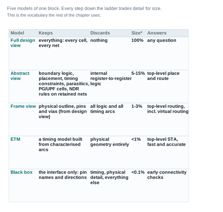
| Abstract view | A reduced model of a block that keeps only its boundary logic, PG, blockages and timing arcs, for use at the top level. |
| Frame view | An even smaller model: physical outline, pins and vias only, extracted from the design view, with no logic or timing at all. Every abstract needs a matching frame view to make top-level routing possible. |
| ETM (extracted timing model) | A timing-only model built from characterised arcs, with no physical geometry. |
| Black box | A module represented by its interface alone, pin names and directions, with no netlist, timing or physical content at all. |
| Pin (block pin) | Real, physical connection geometry on a block's boundary, at a pitch, on a layer, with a direction, not merely a name in a netlist. |
| Feedthrough | A top-level net that is routed through a block's interior rather than around it, borrowing the block's own tracks and pin sites. |
| Timing budget | A portion of a chip-level timing requirement, assigned to a block or to the top level, so each piece can be closed on its own number. |
| Rebudgeting | Revising a budget after a block's real optimization result is known, moving slack to wherever it is actually needed. |
| Top-level closure | The process of proving, with real top-level timing, that every block's model and every budget actually held. |
| Transparent hierarchy optimization (THO) | Concurrent optimization of the top level and selected subblock design views, in top-level timing context, with physical block boundaries honored throughout — it lets a boundary-crossing path be optimized once, end to end, without flattening the design. |
| Early data check (EDC) | A policy-driven check run before hierarchical work begins, to catch a design that is not ready to be partitioned. |
Before you cut a design into blocks, prove it is ready to be cut
This chapter restates Nimbus‑8's identity early, so it reads on its own. It is a fictional SoC teaching design: 9.90 million standard cells, 72 SRAM macros, one DDR PHY hard macro, and a 3.20 × 3.20 mm core. It runs four clocks (1.60 GHz, 1.10 GHz, 800 MHz, 200 MHz) and two named scenarios carried forward from every earlier chapter: func_ss_0p72v_125c (worst-case setup) and func_ff_0p88v_m40c (worst-case hold). Its u_sens_tile partition is already closed at block level from Chapters 5 and 6, and stays fixed: 46,200 cells, two SRAM macros, 0.70 × 0.62 mm, 79.6% utilized. This chapter defines the rest of the partition set around it.
The IC Compiler II design planning flow lists design partitioning, generating hierarchical constraints and allocating top-level timing budgets as the first stage of hierarchical work, run before any block is placed. This chapter follows that order: readiness, then partitioning, then everything downstream of it.
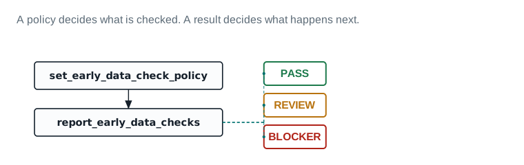
set_early_data_check_policy. The report is generated with report_early_data_checks. Its result routes to one of three outcomes: PASS proceeds, REVIEW needs a named owner and a decision before proceeding, and BLOCKER stops the flow until resolved. Dashboard 1 below is exactly this report, applied to Nimbus‑8.Partitioning is expensive to redo. This board exists so the decision to commit blocks is made on evidence, not on habit carried over from the RTL hierarchy.
| Item | Evidence | Source command / report | Threshold | Status | Required action |
|---|---|---|---|---|---|
| Netlist and constraint completeness | |||||
| 1. Netlist elaborated and linked | 0 unresolved references, 0 black boxes unaccounted for | report_ | 0 unresolved | PASS | — |
| 2. Chip-level SDC complete | All 4 clocks defined, all I/O delays set, 0 unconstrained ports | check_ | 0 unconstrained endpoints | PASS | — |
| 3. Chip-level UPF loaded | 1 power domain (single-voltage baseline), all supply nets defined | load_ | Loads with 0 errors | PASS | — |
| 4. RTL hierarchy inspected, not assumed | Hierarchy browser walked; 3 candidate cuts compared (Figure 2) | hierarchy browser session | At least one alternative to the RTL tree considered | PASS | — |
| Item | Evidence | Source command / report | Threshold | Status | Required action |
|---|---|---|---|---|---|
| Floorplan and macro maturity | |||||
| 5. Core area fixed | 3.20 x 3.20 mm, 10.24 mm^2 | initialize_ | Core area frozen before block shaping | PASS | — |
| 6. All 72 SRAM + 1 DDR PHY identified | 73 macros inventoried, sizes and pin sides known | macro inventory review | 100% of macros identified before shaping | PASS | — |
| 7. I/O placed | place_ run, 100% of I/O pads placed | place_ | 100% placed | PASS | — |
| 8. Utilization target sanity-checked | 81.9% chip-level, no single block target above 82% | arithmetic check against Nimbus-8 totals | No block above 85% (routing headroom) | PASS | — |
| Black boxes and UPF-across-hierarchy readiness | |||||
| 9. Netlist settle window closed | Last RTL change 2 days ago; team norm is a 5-day settle window before committing blocks | design change log | No RTL change in the settle window | REVIEW | Hold commit_ for 3 more days, or get written sign-off from the RTL owner that no further change is expected before then. |
| 10. Block-level UPF strategy defined | Only chip-level UPF exists today; per-block supply nets not yet split out | UPF review | Each planned block has an UPF strategy before shaping | REVIEW | Run split_ to generate block-level UPF alongside SDC once the partition set (Part 4) is final. |
| 11. Black-box references created for un-owned IP | 0 required — Nimbus-8 has no third-party black-box IP in this release | IP inventory | Every un-owned module has a black-box reference or is waived | PASS | — |
| 12. Hierarchy browser data flow reviewed | Data flow analysis run for macro-heavy candidate cuts | hierarchy browser, data flow view | Reviewed before committing blocks | PASS | — |
Readiness verdict for Nimbus-8: 10 PASS, 2 REVIEW, 0 BLOCKER → GO, with two items to close before block shaping begins.
Read it: Read gates 9 and 10 first — both are REVIEW, and both are exactly the kind of gap that looks harmless until a block is already committed. A netlist that has not settled and a UPF file that only exists at chip level are fixable now, cheaply. They are not fixable cheaply after commit_block.
Field values are this chapter's illustrative teaching data.
Reading the readiness verdict
Dashboard 1 is not a formality. It is the evidence that the decision to partition Nimbus‑8 was made on real checks, not on habit. Ten of twelve gates are PASS. Two are REVIEW: the netlist settle window and the block-level UPF strategy. Neither blocks the chapter from proceeding, both are closed explicitly before Part 4 commits the partition set, and the continuity ledger delta records that they were closed, not silently dropped.
Drawing the boundaries, and paying for every one of them
The design planning flow gives four factors to weigh when deciding on physical partitions. Size: group small blocks, split large ones. Function: partition along functional units, watching top-level connectivity and pin count. Floorplan style: an abutted layout implies a different physical hierarchy than a channeled one. And common hierarchy with the front-end tool, so SCANDEF exchanges cleanly between the two. None of those four factors is “whatever the RTL author already grouped together,” and that omission is deliberate.
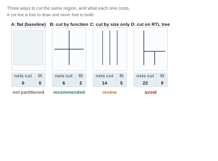
| A: flat (baseline) | 0 nets cut, 0 feedthroughs implied |
|---|---|
| B: cut by function (recommended) | 6 nets cut, 2 feedthroughs implied |
| C: cut by size only (review) | 14 nets cut, 5 feedthroughs implied |
| D: cut on RTL tree (avoid) | 22 nets cut, 9 feedthroughs implied |
Nimbus‑8's partition set
u_sens_tile is fixed: 46,200 standard cells, two SRAM macros, a 0.70 × 0.62 mm footprint, 79.6% utilized. Chapter 6 recorded those numbers publicly and they do not change here. But reconciling them against Nimbus‑8's chip-level totals surfaces something worth stating plainly, in the open, rather than quietly working around.
| Block | Std. cells | SRAM macros | Macro area | Footprint | Utilization |
|---|---|---|---|---|---|
u_sens_tile | 46,200 | 2 (large sensor-buffer, 0.159 mm² each) | 0.318 mm² | 0.70 × 0.62 mm | 79.6% (fixed, Ch. 5–6) |
u_dsp_core | 6,200,000 | 40 | 0.732 mm² | 2.42 × 2.30 mm (illustrative) | 80% (target) |
u_io_ring | 1,200,000 | 20 + 1 DDR PHY | 1.216 mm² | 1.90 × 1.31 mm (illustrative) | 78% (target) |
u_pwr_ctrl | 2,453,800 | 10 | 0.183 mm² | 1.66 × 1.25 mm (illustrative) | 80% (target) |
| Total | 9,900,000 | 72 + 1 DDR PHY | 2.449 mm² | — | 81.9% chip-level |
Cell counts sum to 9,900,000 exactly. Macro area sums to 2.449 mm² against a published 2.45 mm² (rounding on the per-macro average). Every other figure this chapter draws is built against this table, and it is repeated verbatim in qa/continuity-ledger-delta.md.
Committing the blocks
Once the partition set is decided, blocks are committed early in the floorplanning flow so abstract views can generate an initial floorplan and timing budget for the design. Design planning uses read_verilog_outline to read the design, initialize_floorplan to set up the core, place_io for I/O, and commit_block to fix the chosen partition boundaries. Block shaping follows in the same flow: set_macro_constraints constrains the hard macros and I/O cells inside a block (orientation, preferred location, alignment grid), create_keepout_margin adds margin around them, and shape_blocks then shapes and places every shaping object in the design as one set, with respect to constraints and utilization requirements — it is not called per block, it acts once on the whole design's shaping objects together.
Committing and shaping a block Verified
Design planning flow, constraining the two large sensor-buffer SRAM macros inside u_sens_tile (Part 4's reconciliation) before shaping the whole design.
- 1Read the outlined netlist:
read_verilog_outline. - 2Initialize the floorplan:
initialize_floorplan. - 3Explore the hierarchy and fix the boundary:
commit_block. - 4Constrain the hard macros, add keepout margin, then shape the design's shaping objects as a set:
icc2_shell> set_macro_constraints -allowed_orientations {R0 MX} \ [get_cells {u_sens_tile/u_sram_buf0 u_sens_tile/u_sram_buf1}] icc2_shell> create_keepout_margin -type hard_macro -outer {2.0 2.0 2.0 2.0} \ [get_cells {u_sens_tile/u_sram_buf0 u_sens_tile/u_sram_buf1}] icc2_shell> shape_blocks -pg_strategy nimbus8_sensor_pgset_macro_constraintsandcreate_keepout_marginboth take a positional object collection, not-blocks, and both operate on hard macros or I/O cells — not on the physical block itself.-outertakes a four-value margin list,{left bottom right top}, not a single number.shape_blockstakes no object list at all: it shapes every shaping object of the current design together.-pg_strategytakes the name of a strategy already created withset_pg_strategy, not a keyword —nimbus8_sensor_pgabove is that strategy's name, not an enum value.
A pin is geometry, and a feedthrough is a borrowed room
A netlist pin is a name and a direction. A physical pin is a rectangle of real metal, on a real layer, at a real coordinate, obeying that layer's preferred routing direction, and until it has all four of those properties, nothing at the top level can actually connect to it. This Part is about giving every block boundary that real geometry, and about the one mechanism, the feedthrough, that lets a top-level net cross a block it does not belong to.
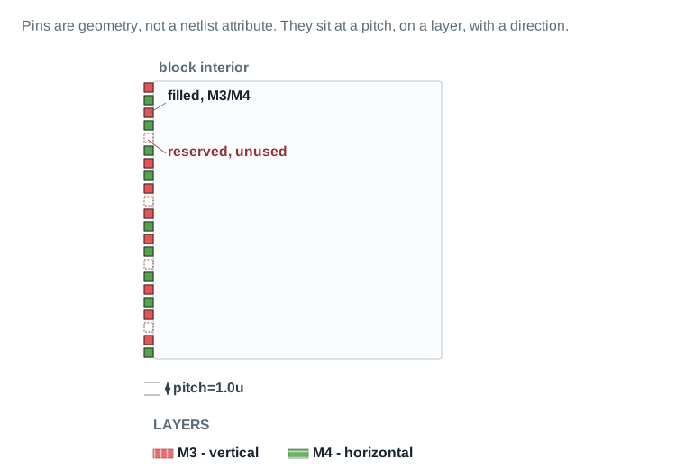
| Pins placed | 18 of 22 available slots on this edge |
|---|---|
| Pin pitch | 1.0 µm, M3/M4 |
| Slots reserved, unused | 4 (headroom for a later ECO) |
Pin constraints are set with create_pin_constraint before pins are actually placed with place_pins, which performs global routing for pin locations honoring individual and bundle constraints, layer, width, length and spacing requirements. A pin blockage can be created first with create_pin_blockage to reserve a region no pin may use.
Assigning pins on a block edge Verified
u_sens_tile's boundary, individual pin constraints.
- 1Constrain a pin's edge and layer:
create_pin_constraint. The edge and layer options are plural,-sidesand-layers, even for a single pin.icc2_shell> create_pin_constraint -type individual \ -pins {sens_data_out[0]} -sides {1} -layers {M3} - 2Repeat for every constrained pin, or leave the rest to the placer.
- 3Place pins for the current block:
place_pins. - 4Check legality:
check_legality.
Feedthroughs: with, and without
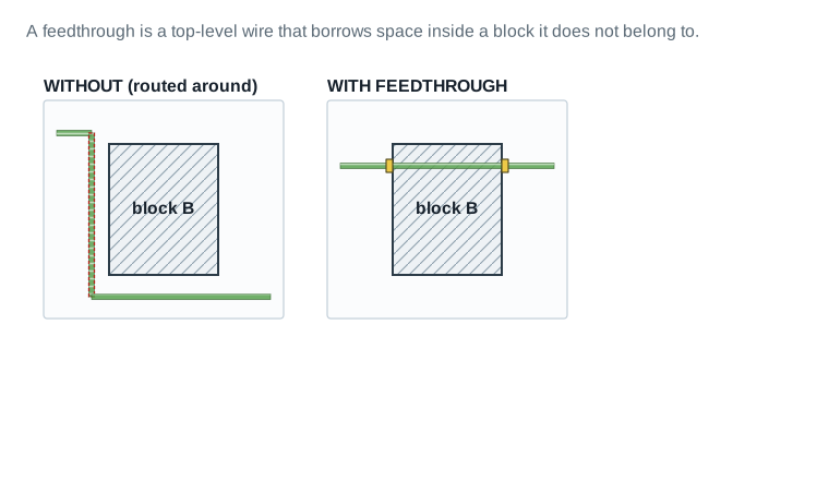
| Pins added to the block | +2 (routed around: 0) |
|---|---|
| Internal track consumed | +1 track through the block |
| Added wire length | +40 µm vs. the routed-around path |
| Added delay | +18 ps |
When a block contains feedthrough nets, push_down_objects creates an electrically equivalent port on the lower-level block where the net crosses it; specifying -allow_feedthroughs true with create_pin_constraint creates an actual feedthrough port in the lower block instead. Feedthroughs pushed down from the top carry the is_shadow attribute on their pins, nets and buffers, marking them as not the block's own logic.
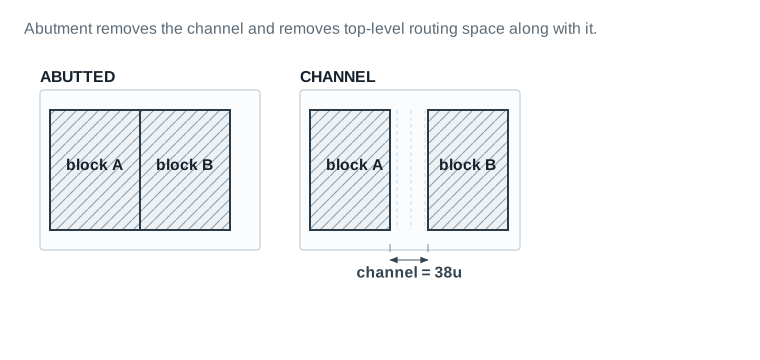
| Abutted: top-level routing space | 0 — no channel exists |
|---|---|
| Channel: top-level routing space | 38 µm wide channel, 5 tracks on M5 |
| Abutted: area saved | +38 µm x block height reclaimed |
Feedthrough sharing on a multiply instantiated block
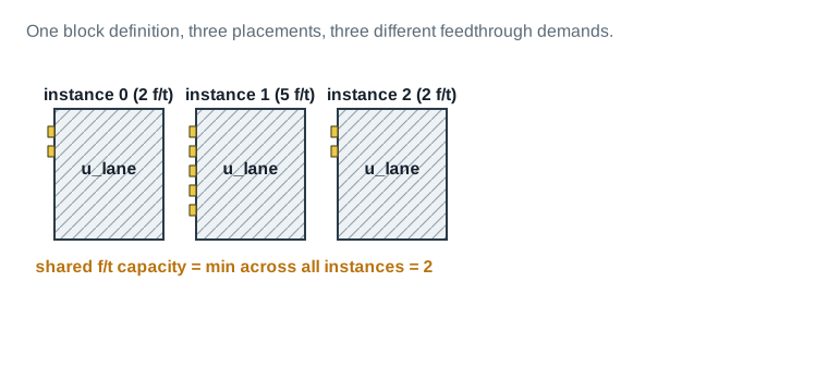
| Instance 0 feedthrough need | 2 |
|---|---|
| Instance 1 feedthrough need | 5 |
| Instance 2 feedthrough need | 2 |
| Shared feedthrough capacity | min(2, 5, 2) = 2 — instance 1 cannot use the shared definition as-is |
Feedthrough sharing in multiply instantiated blocks is constrained exactly this way: a shared block definition can only offer the feedthrough paths every instance can accommodate. Instance 1's extra three feedthroughs need either a second, dedicated definition or a top-level routing plan that does not depend on this block carrying them.
Splitting one number across blocks that cannot see each other
A path that starts in one block, crosses the top level, and ends in another block has one timing requirement as a whole, but no single tool run can ever see the whole path at once, because each block is closed largely on its own. Budgeting is the step that turns one chip-level requirement into pieces small enough for a block, working alone, to close against.
To support budgeting, chip-level SDC and UPF are partitioned into top-level and block-level files, using split_constraints when only chip-level constraints exist yet. The timing budgeter itself works in four steps: create lightweight timing abstracts for the blocks with create_abstract, virtually optimize each block with estimate_timing to get a realistic starting timing picture, apply any manual constraints with set_pin_budget_constraints and set_boundary_budget_constraints, update the computed budget with compute_budget_constraints, and write the result out with write_budgets. The budgeter is fully multimode, multicorner aware, and understands multiply instantiated blocks.
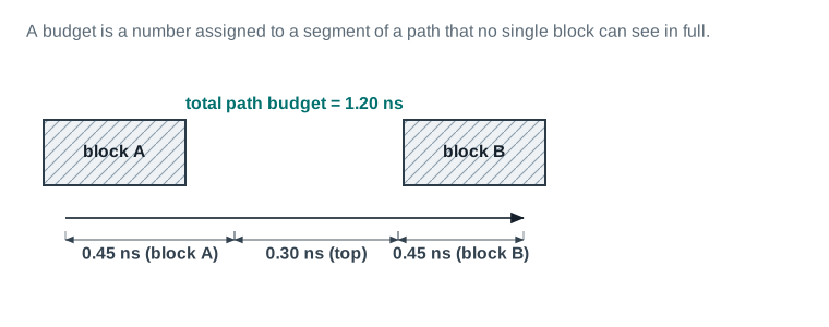
| Total path budget | 1.20 ns |
|---|---|
| Block A share | 0.45 ns |
| Top-level share | 0.30 ns |
| Block B share | 0.45 ns |
Generating a timing budget Verified
The four-step budgeter flow, applied chip-wide.
- 1Split chip-level constraints if needed:
split_constraints. - 2Create block timing abstracts:
create_abstract. - 3Virtually optimize each block:
estimate_timing. - 4Compute and write the budget. The pin list is positional, not
-pins, and the split is stated with-from_delay: this pin is the boundary a path arrives at, so 0.45 ns is the delay allocated from the start of the path up to this pin, with whatever remains left for the segment past it.icc2_shell> set_pin_budget_constraints -from_delay 0.45 {sens_data_out[0]} icc2_shell> compute_budget_constraints icc2_shell> write_budgets -output nimbus8_budgets_v1
Rebudgeting
A budget is a starting point, not a promise held in place forever. Once a block has actually been placed and optimized, its real result is known, and that real result almost never matches the initial split exactly.
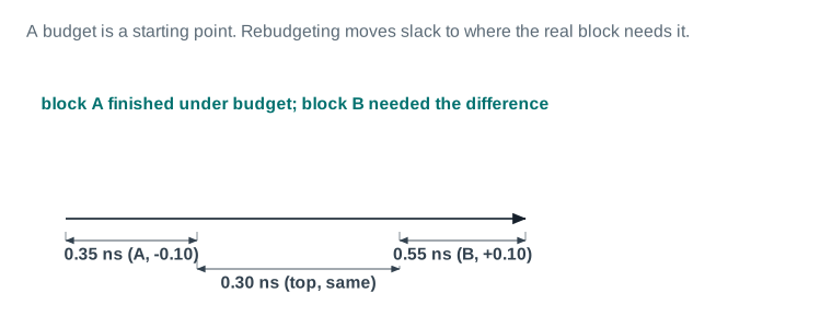
| Block A: budget vs. closed | 0.45 ns budget, closed at 0.35 ns (-0.10 ns to spend elsewhere) |
|---|---|
| Top-level share | 0.30 ns, unchanged |
| Block B: budget vs. closed | 0.45 ns budget, needs 0.55 ns (+0.10 ns moved from block A) |
An interface is not one property. It is six, and a block can be PASS on five of them and still be unusable at the top level because of the sixth.
| Item | Evidence | Source command / report | Threshold | Status | Required action |
|---|---|---|---|---|---|
| u_sens_tile (46,200 cells, 2 sensor-buffer SRAMs) | |||||
| 1. Pins assigned | 18 pins, pitch 1.0 um, M3/M4 | place_ | 100% of declared pins placed | PASS | — |
| 2. Pin-layer legality | 0 layer-direction violations | check_ | 0 violations | PASS | — |
| 3. Feedthroughs | 2 in, 0 out | push_ | Declared count matches top-level net list | PASS | — |
| 4. Budget assigned | 0.45 ns on the sensor-read critical path | set_ | Every timing-critical pin has a budget | PASS | — |
| 5. Constraints split | Block-level SDC and UPF generated | split_ | Block file exists and loads clean | PASS | — |
| 6. PG at boundary | Mesh continuity verified at abutment edges | PG connectivity check | 0 opens at the boundary | PASS | — |
| Item | Evidence | Source command / report | Threshold | Status | Required action |
|---|---|---|---|---|---|
| u_dsp_core (6,200,000 cells, 40 SRAMs) | |||||
| 7. Pins assigned | 212 pins, pitch 1.0 um, M3/M4 | place_ | 100% placed | PASS | — |
| 8. Pin-layer legality | 0 violations | check_ | 0 violations | PASS | — |
| 9. Feedthroughs | 6 in, 3 out | push_ | Declared count matches top-level net list | PASS | — |
| 10. Budget assigned | 0.60 ns worst-case on the DSP MAC path | set_ | Every timing-critical pin has a budget | PASS | — |
| 11. Constraints split | Block-level SDC and UPF generated | split_ | Block file exists and loads clean | PASS | — |
| 12. PG at boundary | Mesh continuity verified | PG connectivity check | 0 opens | PASS | — |
| Item | Evidence | Source command / report | Threshold | Status | Required action |
|---|---|---|---|---|---|
| u_io_ring (1,200,000 cells, 20 SRAMs, DDR PHY) | |||||
| 13. Pins assigned | 348 pins (incl. DDR PHY I/O), M3/M4/M5 | place_ | 100% placed | PASS | — |
| 14. Pin-layer legality | 0 violations | check_ | 0 violations | PASS | — |
| 15. Feedthroughs | 9 in, 5 out — highest in the design | push_ | Declared count matches top-level net list | REVIEW | 9 in / 5 out is high for one block. Review with the floorplan owner whether one feedthrough can move to an abutted path instead (Part 5). |
| 16. Budget assigned | 0.80 ns worst-case, DDR PHY calibration path | set_ | Every timing-critical pin has a budget | PASS | — |
| 17. Constraints split | Block-level SDC and UPF generated | split_ | Block file exists and loads clean | PASS | — |
| 18. PG at boundary | Mesh continuity verified | PG connectivity check | 0 opens | PASS | — |
| u_pwr_ctrl (2,453,800 cells, 10 SRAMs) | |||||
| 19. Pins assigned | 96 pins, M3/M4 | place_ | 100% placed | PASS | — |
| 20. Pin-layer legality | 0 violations | check_ | 0 violations | PASS | — |
| 21. Feedthroughs | 3 in, 2 out | push_ | Declared count matches top-level net list | PASS | — |
| 22. Budget assigned | 0.35 ns worst-case, power-switch enable path | set_ | Every timing-critical pin has a budget | PASS | — |
| 23. Constraints split | Block-level SDC generated; UPF strategy still pending (Dashboard 1, item 10) | split_ | Block file exists and loads clean | REVIEW | Close Dashboard 1 item 10 before this block's UPF is considered final. |
| 24. PG at boundary | Mesh continuity verified | PG connectivity check | 0 opens | PASS | — |
Interface verdict: 4 blocks, 22 PASS, 2 REVIEW, 0 BLOCKER → all four interfaces usable for top-level assembly, with 2 items to close before final closure.
Read it: u_sens_tile is the block carried over from Chapters 5 and 6; its feedthrough count (2) and budget (0.45 ns) are the numbers Figure 15C draws. u_io_ring carries the DDR PHY and shows the highest feedthrough count, which is expected of a periphery block that other blocks route through to reach pads.
Field values are this chapter's illustrative teaching data.
Keeping the boundary, discarding everything behind it
In an abstract view, a block's gate-level netlist is modelled by a partial netlist. That partial netlist keeps only the required interface logic: everything between an input port and the first register of each timing path, everything between the last register of a path and an output port, any pure input-to-output combinational logic, and the clock connections and clock trees that drive the preserved registers. Register-to-register logic in the interior is discarded entirely.
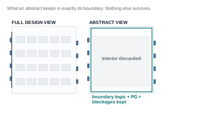
| Cells kept | boundary-adjacent logic only, ~5-15% of the block |
|---|---|
| Cells discarded | all register-to-register interior logic |
| File size vs. full view (illustrative) | ~8% for u_sens_tile's abstract |
| Measured interface error | 4 ps worst-case arc (Dashboard 3) |
Creating an abstract uses create_abstract. Its options preserve power information, keep signal electromigration data, preserve minimum pulse-width analysis, and handle multiple levels of physical hierarchy. The one setting that matters most for how much of the interface an abstract actually keeps is -timing_level, covered below. create_abstract -preserve_block_instances false and read-only variants exist for specific top-level closure needs. report_abstract_inclusion_reason explains, for a given included object, why it was kept — it reports inclusion only, never discards, and it does not report for hierarchical cells or pins on hierarchical cells. It is useful when an abstract's size looks larger than expected: you find out why the things that are there are there, not why something you expected is missing.
Creating and reading an abstract Verified
u_sens_tile, once its pins and budget are final.
- 1Confirm pins and budget are final (Parts 5–6). Do not build the abstract before this.
- 2Create the abstract:
create_abstract -timing_level compact. - 3Check why an object was included:
report_abstract_inclusion_reason. Reported reason codes come from a fixed legend —mvfor MV logic,compfor compact interface logic,cellfor cell inclusion — and one object can carry several.icc2_shell> report_abstract_inclusion_reason [get_pins \ -of_objects [get_cells sens_buf_reg*]]get_pinstakes-of_objects, plural — the User Guide prints-of_object, singular; the Tool Command Reference spelling above is authoritative. - 4Save the block:
save_block.
Choosing a timing level
create_abstract -timing_level none(deprecated)|boundary|compact|full_interface is the fidelity dial that decides how much boundary timing an abstract keeps, and it trades memory and runtime against accuracy directly. none is marked deprecated and slated for removal in the Tool Command Reference, so the table below covers only the three settings actually worth choosing between:
| Setting | What it keeps | When to use it |
|---|---|---|
boundary | Boundary cells only, one level of logic per boundary port, plus feedthrough data paths, feedthrough combinational clock paths, and internal clock logic driving output ports. | Fixing DRC violations at the top level. |
compact — default | Timing for the critical setup and hold paths of the interface logic only. | Preferred for top-level design closure; this is what u_sens_tile uses. |
full_interface | Timing for all interface logic, not just the critical paths. | Multiply-instantiated blocks (MIBs), when the constraints for different MIB instances differ at the top level. |
This connects straight back to Part 4's MIB material. A MIB placed at three sites can face three different top-level timing contexts, and compact only carries the critical paths against one of them. full_interface is what lets every instance's own constraints show up in its own abstract's timing, which is exactly the mismatch Figure 8 and interview questions 18 and 31 are built around. -blocks / -all_blocks create lower-level abstracts in bulk, -force_recreate rebuilds even when the tool thinks an abstract is current, and -include_objects forces specific objects into the abstract that the timing level alone would not keep. -target_use planning | implementation changes the tool's internal settings based on how the abstract will be used. -read_only works the opposite way from what its name suggests: a read-only abstract leaves the block's own design view editable, while the default (not read-only) makes the design view read-only once an abstract references it.
If a block changes after its abstract was created, the abstract has to be regenerated, it is not automatically kept in sync. Abstract views can also be shrunk further while maintaining timing accuracy on the arcs they still carry, and the PG structure can be recreated on an existing abstract without rebuilding the whole thing from the design view. A frame view goes one step further: physical outline, pins and vias only — blockage, pin, and via information extracted from the design view, with no logic or timing arcs at all — created with create_frame. Every abstract view must have a corresponding frame view to perform top-level routing, including virtual routing, which is the reason a frame view exists at all, not just a lighter-weight convenience for congestion estimation.
Linking abstracts at the top level
At the top level, report_abstracts reports which abstract views the design is linking to. Because the tool does not currently modify abstract contents during top-level closure, abstracts used this way can be created read-only. If a block needs to change between its abstract and its full design view, the command is change_abstract -view design|abstract -references <block>. Switching a block to its design view is not a one-line swap: it requires removing the scenarios, modes and corners built against the abstract, then re-applying the full-chip timing constraints, because the design view exposes internal structure the abstract's constraints were never written against.
icc2_shell> remove_scenarios -all
icc2_shell> remove_modes -all
icc2_shell> remove_corners -all
icc2_shell> change_abstract -view design -references u_sens_tile
icc2_shell> source full_chip_scenario_creation.tcl
link_block -rebind is a different operation: it relinks a reference after the label switch list has been changed with set_label_switch_list, not after an abstract/design view switch. Switching between an ETM and an abstract is a third command again, set_reference (Part 8). Also available: change_abstract -reload reloads a changed abstract from disk; report_abstracts reports which abstracts the design links to; remove_abstract removes an abstract and returns the design view to editable.
A model is a lie of a known size. This board is where the size gets written down, so a stale model is caught before it costs a top-level closure cycle.
| Item | Evidence | Source command / report | Threshold | Status | Required action |
|---|---|---|---|---|---|
| Model choice and what it omits | |||||
| 1. u_sens_tile | Abstract — small, stable interface, top-level route needs real boundary geometry | create_ | Omits: all register-to-register logic inside the tile | PASS | — |
| 2. u_dsp_core | Abstract — large block, top-level place and route still needs its physical boundary | create_ | Omits: all internal DSP datapath logic | PASS | — |
| 3. u_io_ring | Abstract — DDR PHY pin geometry must be visible for top-level pad-ring routing | create_ | Omits: PHY calibration logic interior | PASS | — |
| 4. u_pwr_ctrl | ETM — small block, high pin-to-logic ratio, top-level STA needed fast and accurate more than physical detail | extract_model (ICC2) | Omits: physical geometry entirely | PASS | — |
| Measured error and staleness | |||||
| 5. u_sens_tile error vs full view | 4 ps worst-case interface arc (Figure 15D) | abstract-vs-full timing comparison | ≤ 10 ps on any interface arc | PASS | — |
| 6. u_dsp_core error vs full view | 7 ps worst-case interface arc | abstract-vs-full timing comparison | ≤ 10 ps on any interface arc | PASS | — |
| 7. u_io_ring error vs full view | 6 ps worst-case interface arc | abstract-vs-full timing comparison | ≤ 10 ps on any interface arc | PASS | — |
| 8. u_pwr_ctrl error vs full view | 3 ps worst-case interface arc | ETM-vs-full timing comparison | ≤ 10 ps on any interface arc | PASS | — |
| 9. u_sens_tile regenerated vs changed | Regenerated 1 day after last block edit | model timestamp vs block edit log | Regenerated within 14 days of any edit | PASS | — |
| 10. u_pwr_ctrl regenerated vs changed | ETM regenerated 9 days after last block edit | model timestamp vs block edit log | Regenerated within 14 days of any edit | REVIEW | Still inside policy, but close to it. Schedule the next ETM regeneration for this block first. |
Fidelity verdict: 4 models in use (3 abstract, 1 ETM), 3 PASS, 1 REVIEW → usable for top-level closure, with one regeneration due.
Read it: The Regenerated vs Changed column is the one to watch. u_pwr_ctrl's ETM is 9 days older than the block's last edit — still inside this project's 14-day staleness policy, but close enough to flag.
Field values are this chapter's illustrative teaching data.
When an abstract is not accurate enough
An extracted timing model, or ETM, is a timing-only model with no physical geometry at all, built instead from characterised timing arcs across every mode and corner the block needs. It is more accurate than an abstract for pure timing questions, because it is not derived from geometry at all; it is measured, arc by arc, against the real block.
ETMs can be created directly in the ICC2 tool with extract_model, after a frame view is created for library preparation and PrimeTime options are set; StarRC parasitic extraction can be selected explicitly. The same command combines timing extraction and cell-library packaging in one step. Alternatively, ETMs can be created per scenario in the PrimeTime tool itself, reading the block's netlist and parasitics, applying UPF and mode/corner constraints, and calling extract_model -library_cell -format db; for multicorner-multimode designs, one ETM is required per scenario. A third path builds ETM cell libraries in the Library Manager tool, combining PrimeTime-created ETMs with physical information.
Creating an ETM in the ICC2 tool Verified
u_pwr_ctrl, chosen for an ETM over an abstract (Dashboard 3).
- 1Open the block and create a frame view:
create_frame. - 2Set PrimeTime options and a post-link script.
- 3Optionally select StarRC extraction:
set_app_options -name extract.starrc_mode -value true. - 4Create the ETM and its cell library:
extract_model.
Errata: the User Guide printsicc2_shell> create_frame icc2_shell> set_pt_options -pt_exec <path> -work_dir ETM_work_dir icc2_shell> extract_model-pt_exec_path; the Tool Command Reference spells it-pt_exec, confirmed in its own worked examples. The Tool Command Reference is authoritative — use-pt_exec.
Choosing a model: abstract, frame or ETM
Return to Figure 2's model ladder. An abstract is the right default when the top level still needs real boundary geometry, place and route, congestion, physical DRC near the boundary. A frame is the right choice when even abstract-level timing is more than is needed, typically early floorplanning. An ETM is the right choice when a block's pin-to-logic ratio is high, its physical detail rarely matters to the top level, and top-level STA speed and accuracy both matter more than geometry, exactly Nimbus‑8's u_pwr_ctrl, per Dashboard 3.
Proving every promise the earlier Parts made was true
Every block in Nimbus‑8's partition set can close cleanly at block level and the top level can still fail. That is not a contradiction. It is the direct, structural consequence of every block being closed against a model of its neighbours rather than against the neighbours themselves.
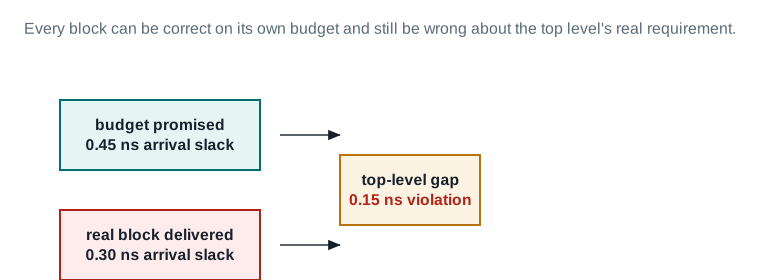
| Budget promised | 0.45 ns arrival slack |
|---|---|
| Real block delivered | 0.30 ns arrival slack |
| Top-level gap inherited | 0.15 ns violation |
Preparing for top-level closure with abstracts means checking designs with abstracts for top-level-closure issues before running full closure, check_hier_design -stage timing is the check used at the top-level design. Once abstracts are in place, top-level synthesis, placement, optimization, clock tree synthesis, routing and postroute optimization can all run using the same commands supported at block level.
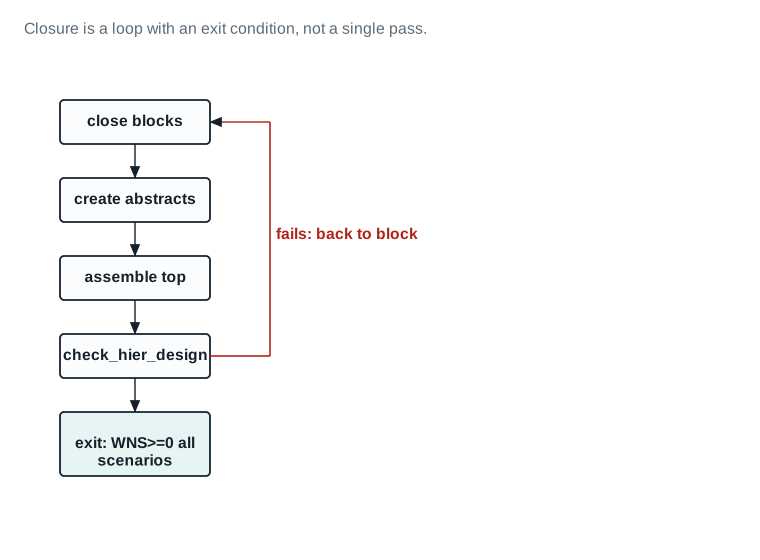
check_hier_design. If the check fails, the red path returns to a block for another pass. If it passes with WNS ≥ 0 in every scenario, the loop exits. This is a loop with a real exit condition, not a single one-way pass.Top-level closure loop Verified
- 1Check for closure issues before assembling:
check_hier_design -stage timing. - 2Assemble and optimize the top level using abstracts, then re-check.
- 3Report where a boundary still violates:
report_timing,report_qor. - 4If a block needs another pass, return to it, close, regenerate its abstract, and re-assemble.
Transparent hierarchy optimization
Rebudgeting fixes a stale split. It does not fix a boundary path whose real delay never had a chance to be seen by either optimizer, because each side only ever worked from a guess about what the other side would deliver. Transparent hierarchy optimization (THO) closes that gap without giving up the hierarchy: it opens selected subblock design views and optimizes them together with the top level, in the context of top-level timing, so an interblock or block-to-top path is optimized once, end to end, by one engine, with CCD, AWP and PrimeTime delay calculation available across it. THO honors the physical block boundaries throughout. It does not move logic across a boundary, it does not change a subblock's shape, and it does not change the physical hierarchy. By default it does not even move pins — there is an option to let it reassign pin locations to improve QoR, and that is the only boundary-adjacent thing it may touch. Because the hierarchy never flattens, signoff extraction and PrimeTime STA can still run hierarchically, and late ECOs stay easier to implement.
THO runs at two points in the flow: during the final_opto stage of place_opt, and during route_opt or hyper_route_opt at postroute. Both are points where placement, and later routing, are settled enough that a cross-boundary path has a real delay to optimize against — running it earlier would mean optimizing against geometry that has not converged yet.
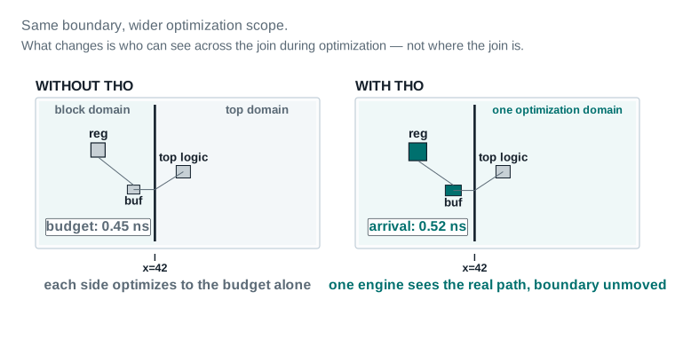
| Optimization scope | block-only → top level + block, concurrent |
|---|---|
| Boundary geometry | unchanged — same position, both panels |
| Pin locations | honored (default; not reassigned) |
| Path WNS, before → after | -0.07 ns → +0.006 ns, this boundary |
Applying THO Verified
- 1Open the libraries in edit mode:
open_lib top.nlib -ref_libs_for_edit. The design view of each participating block must be editable. - 2Switch the blocks you want to optimize from abstract to design view:
change_abstract -view design -references <blk>(see Part 7 for the full constraint-removal sequence this requires). - 3Enable editing on those blocks:
set_editability -blocks {u_sens_tile u_dsp_core} -value true, and verify withreport_editability -blocks [get_blocks -hierarchical]. - 4Set the scope:
set_hierarchy_options -optimize_interface_only trueopens only the interface logic for optimization;falseopens the whole subblock.set_hierarchy_options -optimize_shared_logic unrestrictedalso opens logic shared between the interface and register-to-register paths. Report the settings withreport_hierarchy_options. For distributed subblock work, addset_host_optionsandset_hierarchy_options -host_option— without them, subblock operations run serially in the main process. - 5Run THO at the final optimization stage:
icc2_shell> init_hier_optimization -flow pre_route icc2_shell> place_opt -from final_opto -to final_opto icc2_shell> commit_hier_optimizationinit_hier_optimizationis what turns THO on for the run that follows, and it also triggers automatic promotion of block-level CCD useful-skew and latency offsets into the top-level timing context.commit_hier_optimizationwrites the result back. Skip either one andplace_opt -from final_optois an ordinary optimization pass, not THO. - 6Rebudget. After a THO
place_opt, block interface timing no longer matches the standalone implementation, so the blocks need updated constraints beforeclock_opt. CCD balance-point offsets may have moved and must be made block-context-specific. - 7Run THO at postroute, on the same bracketing pattern:
ECO routing after optimization runs on every subblock that is open for editing.icc2_shell> init_hier_optimization -flow post_route icc2_shell> route_opt ;# or hyper_route_opt icc2_shell> commit_hier_optimization
This is the board that decides whether the loop in Figure 11 exits or sends a block back.
| Item | Evidence | Source command / report | Threshold | Status | Required action |
|---|---|---|---|---|---|
| Top-level timing per scenario | |||||
1. WNS, func_ | +0.006 ns | report_ | WNS ≥ 0 | PASS | — |
2. TNS, func_ | 0 ns | report_ | TNS = 0 | PASS | — |
3. WNS, func_ | +0.011 ns | report_ | WNS ≥ 0 | PASS | — |
4. TNS, func_ | 0 ns | report_ | TNS = 0 | PASS | — |
| Interface violations by block | |||||
| 5. u_sens_tile interface | 0 violations | check_ -stage timing | 0 | PASS | — |
| 6. u_dsp_core interface | 0 violations | check_ -stage timing | 0 | PASS | — |
| 7. u_io_ring interface | 1 violation, 0.008 ns, before rebudgeting | check_ -stage timing | 0 | PASS | Resolved by the rebudgeting pass in Part 6 (Figure 10); 0 remaining. |
| 8. u_pwr_ctrl interface | 0 violations | check_ -stage timing | 0 | PASS | — |
| Item | Evidence | Source command / report | Threshold | Status | Required action |
|---|---|---|---|---|---|
| Feedthrough timing and clock trunk arrival | |||||
| 9. Feedthrough delay, worst case | +18 ps, u_io_ring feedthrough (Figure 6) | top-level timing report on feedthrough net | Within the block's assigned budget | PASS | — |
| 10. Clock trunk arrival at u_sens_tile boundary | 0.312 ns insertion delay, 6 ps skew to sibling | clock trunk report | Within clock-tree budget for this level | PASS | — |
| 11. Clock trunk arrival at u_dsp_core boundary | 0.298 ns insertion delay, 5 ps skew to sibling | clock trunk report | Within clock-tree budget for this level | PASS | — |
| Transparent hierarchy optimization | |||||
| 12. THO applied during place_opt final_opto | u_io_ring/top boundary optimized concurrently; boundary unmoved, pins honored (Figure 14) | init_ -flow pre_route | Applied wherever a boundary path benefits from concurrent top+block optimization | PASS | — |
| 13. THO applied during route_opt | 0 changes needed — place_opt's pass closed the gap | route_ | — | PASS | — |
Closure verdict: WNS +0.006 ns / TNS 0 ns on func_ss_0p72v_125c, WNS +0.011 ns / TNS 0 ns on func_ff_0p88v_m40c → top-level closure PASS, both scenarios.
Read it: The top-level WNS is positive but small — +0.006 ns on the tighter scenario. That is the margin the budgets in Part 6 were built to protect. Read it as a result that is correct, not as one that is comfortable.
Field values are this chapter's illustrative teaching data.
u_sens_tile through the whole hierarchical flow, one region, four panels
u_sens_tile is the one partition this guide has followed since Chapter 5. This Part follows it through the rest of the hierarchical flow, the same region, the same coordinates, in every panel, pairing what the block's structure is at each stage against what it costs.
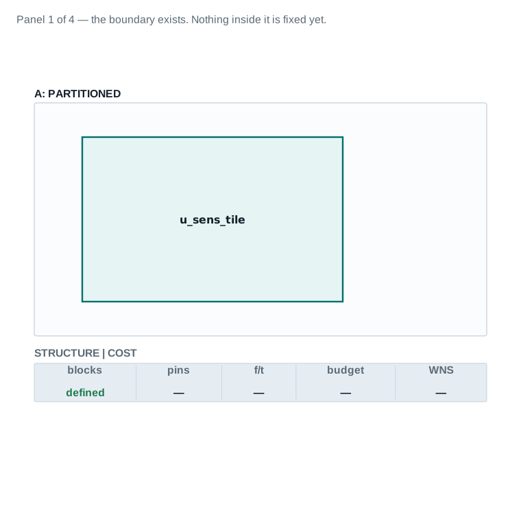
u_sens_tile is fixed, from Part 4's partition set. The status strip shows blocks defined; pins, feedthroughs, budget and WNS all show —, not yet decided.| Blocks defined | yes |
|---|---|
| Pins / f/t / budget | not yet |
| Interface slack / model error / top WNS | n/a / n/a / n/a |
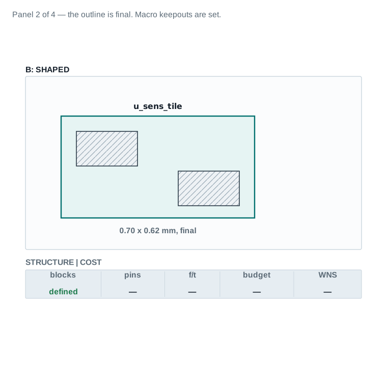
| Shape final | yes, 0.70 x 0.62 mm |
|---|---|
| Pins / f/t / budget | not yet |
| Interface slack / model error / top WNS | n/a / n/a / n/a |
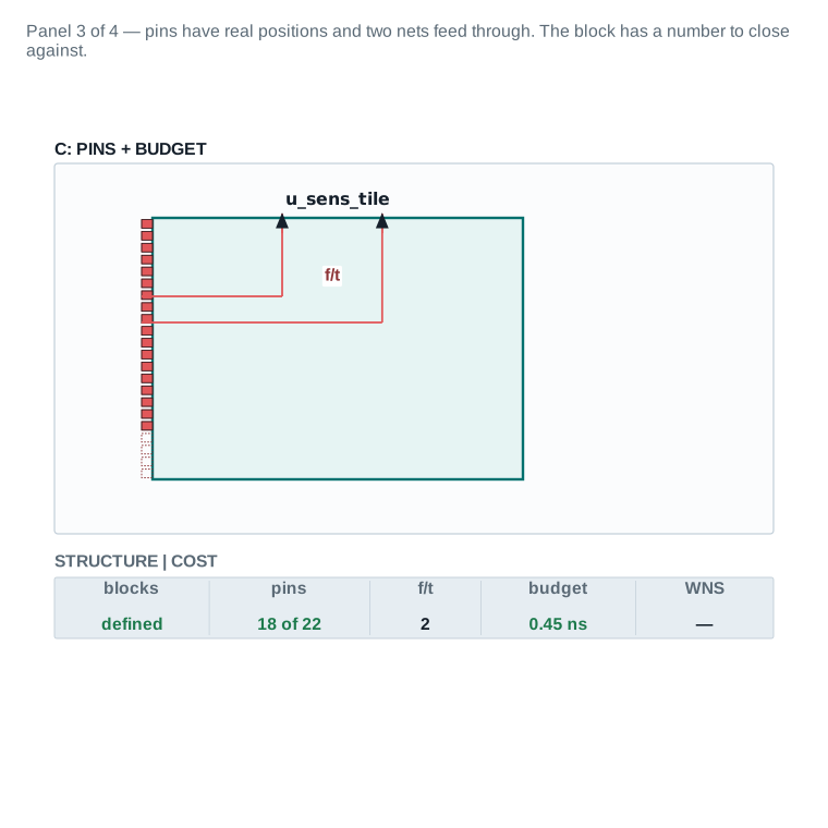
| Pins assigned | 18 of 22 slots |
|---|---|
| Feedthroughs | 2 |
| Budget assigned | 0.45 ns |
| Interface slack | +0.04 ns |
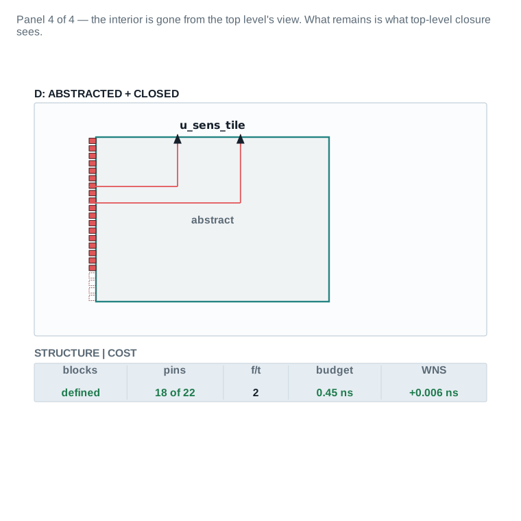
| Model | abstract |
|---|---|
| Size (illustrative) | ~8% of full view |
| Top-level check | PASS |
| Model error | 4 ps worst-case arc |
| Top-level WNS | +0.006 ns |
Read the four panels as one continuous story. A boundary with nothing decided (15A) becomes a shaped outline (15B). That outline becomes a block with real pins, two feedthroughs and a real number to hit (15C). It finally becomes the reduced model the top level actually sees, checked and passing (15D). The same five status-strip fields — blocks, pins, f/t, budget, WNS — run across all four panels, filling in left to right as the block moves through the flow. Every number in 15C and 15D traces back to a figure or dashboard earlier in this chapter; nothing here is invented for the worked example alone.
Partition, pin, budget and close a block yourself
Here is the orientation for this Part. Reading about a budget split is not the same as watching one actually fail to add up. This lab is built around one small region, taken through the whole flow, with one deliberate mistake in the middle of it.
Exercise 1, Compare three candidate cuts before choosing one
Using the hierarchy browser, pick a region of your design with at least two natural sub-blocks. Propose three different ways to cut it: by function, by size alone, and along the RTL module tree, matching Figure 4. For each, count the nets crossing the cut and the feedthroughs implied.
Close with: three candidate cuts, each with a net-crossing count. PASS if you can state, in one sentence, why your chosen cut beats the other two.
Exercise 2, Commit and shape a block
Commit your chosen block boundary with commit_block, constrain its hard macros with set_macro_constraints and their keepouts with create_keepout_margin, then run shape_blocks once for the whole design — it shapes every shaping object together, it is not called per block. Record the resulting footprint.
Close with: a committed, shaped block and its footprint dimensions. PASS if the shaped outline respects every macro keepout you declared.
Exercise 3, Assign pins and push one feedthrough through
Assign pins on your block's boundary with place_pins. Then identify one net that would naturally cross your block's footprint, and push it through as a feedthrough with push_down_objects, rather than routing it around.
Close with: a pin count, and one feedthrough with its added pin count, track and length recorded, matching Figure 6's ledger format. PASS if the feedthrough's cost is stated in the same four numbers Figure 6 uses.
Exercise 4, Budget a boundary-crossing path
Pick one timing path that crosses your block's boundary. Split its total requirement into a block segment, a top-level segment and (if it crosses two blocks) a second block segment, using set_pin_budget_constraints and compute_budget_constraints.
Close with: a budget split that sums to the path's total requirement. PASS if the three segments add up exactly.
Exercise 5, The deliberate mistake
This is the exercise that teaches the chapter. You are going to build an abstract before the block's pins are actually final, on purpose.
- Assign pins as in Exercise 3, and build an abstract from that state with
create_abstract. Record the abstract's pin count. Call this A. - Now, without rebuilding the abstract, move one pin, change its side or layer, as if a late floorplan change forced it.
- Report the abstract's pin count again. Call this B.
- Now rebuild the abstract with
create_abstractand report the pin count a third time. Call this C.
You will find that B equals A, and C does not. Moving the real pin did nothing to the already-built abstract, it kept reporting the old geometry. Only rebuilding it produced a model that matched the real block. Any top-level work done against B's abstract in between was done against geometry that no longer existed.
Close with: three pin counts, A, B and C, and one sentence explaining why B was unsafe to use. PASS if C differs from A and you can say why B was the dangerous one, not C.
Exercise 6, Run a top-level closure loop and force one failure
Assemble a small top level using your block's abstract. Run check_hier_design -stage timing. Then deliberately set one boundary budget slightly tighter than what Exercise 4 showed the block could actually deliver, and re-run the check.
Close with: one clean closure result, and one deliberately forced failure, with a one-sentence diagnosis of which mechanism from Figure 12 caused it. PASS if your diagnosis names the specific budget-versus-real-block gap, not a vague “timing failed.”
Exercise 7, Write the exit state
Using Part 12's checklist, write a one-page exit state for your lab block: model type, top-level status, checkpoint name, and what a downstream ECO engineer would need to know.
Close with: a written exit state matching Figure 16's four fields. PASS if every field is filled with a real value, not a placeholder.
What leaves this stage, stated once, completely
Chapter 8, ECO Flow, needs more than a checkpoint file. It needs to know, per block, what closed, what model represents it, what the top level's real timing is, and which saved artifact proves each of those claims. This Part writes that down once, completely, rather than leaving it implicit in a folder of files.
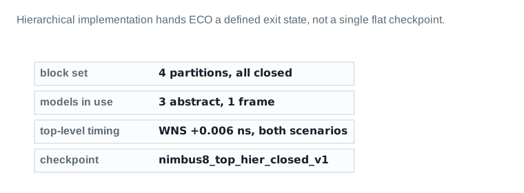
nimbus8_top_hier_closed_v1.Every other board in this chapter feeds this one. This is the board a reviewer who has ten minutes should read.
| Item | Evidence | Source command / report | Threshold | Status | Required action |
|---|---|---|---|---|---|
| Exit criteria and their evidence | |||||
| 1. All 4 blocks closed at block level | 0 setup/hold violations, all blocks, both scenarios | report_ | 0 violations, per block | PASS | nimbus8_<block>_closed_v1 checkpoints |
| 2. Top-level closed | WNS +0.006 ns / +0.011 ns, TNS 0 ns, both scenarios | report_ | WNS ≥ 0, TNS = 0, both scenarios | PASS | nimbus8_top_hier_closed_v1 checkpoint |
| 3. Models regenerated within policy | 4/4 blocks within the 14-day staleness policy | Dashboard 3 | 100% within policy | PASS | Dashboard 3 record |
| 4. Feedthroughs accounted for | 20 feedthrough nets total, all pushed down and budgeted | push_ | 100% accounted for | PASS | Dashboard 2 record |
| 5. PG continuous at every boundary | 0 opens, all 4 blocks | PG connectivity check | 0 opens | PASS | Dashboard 2 record |
| 6. Early data checks clear | 0 BLOCKER, 0 REVIEW outstanding | report_ | 0 BLOCKER at exit | PASS | EDC report, saved |
| 7. Partition arithmetic reconciled | 9.90M cells / 2.45 mm^2 macro area, sums verified | arithmetic check | Sums to Nimbus-8 totals exactly | PASS | qa/continuity-ledger-delta.md |
| 8. Stream-out-ready checkpoint saved | nimbus8_top_hier_closed_v1 | save_ | Checkpoint exists and reopens clean | PASS | nimbus8_top_hier_closed_v1 |
| 9. Handoff package written for ECO Flow | Block set, models, constraints, checkpoint names (Figure 16) | handoff review | All four items present | PASS | qa/continuity-ledger-delta.md |
Stage-exit verdict: 9 PASS, 0 REVIEW, 0 BLOCKER → GO. Nimbus-8 hierarchical implementation is handed to ECO Flow.
Read it: Every row names the saved artifact that proves it, not just a claim. A reviewer who does not trust the claim can open the named checkpoint or report and check it directly.
Field values are this chapter's illustrative teaching data.
Exit checklist
| Item | Evidence | Status |
|---|---|---|
| Partition set defined and reconciled | Part 4 table; qa/continuity-ledger-delta.md | PASS |
| Every block's pins assigned and legal | Dashboard 2 | PASS |
| Every boundary-crossing path budgeted | Dashboard 2, Part 6 | PASS |
| Every block has a chosen, current model | Dashboard 3 | PASS |
| Top level closed, both scenarios | Dashboard 4 | PASS |
| THO scope and result recorded, where applied | Dashboard 4, item 12 | PASS |
| Checkpoint saved and reopens clean | nimbus8_top_hier_closed_v1 | PASS |
| Exit state written for ECO Flow | This Part; delta file | PASS |
Every row above is PASS. Three earlier boards carried a REVIEW: the netlist settle window and block-level UPF strategy in Dashboard 1, the DDR PHY feedthrough count in Dashboard 2, and the ETM staleness margin in Dashboard 3. Each was closed explicitly before this checklist was written. The closure is recorded in qa/continuity-ledger-delta.md, not silently dropped.
40 questions, tiered, every answer grounded in this chapter
Forty questions across four tiers: 14 beginner, 14 intermediate, 8 advanced, and 4 senior/architect. Every answer draws only on what this chapter taught; illustrative numbers are labelled as such, and no new command is introduced in an answer that was not already verified in the body text.
Beginner, 14 questions
- 1. What is a block abstract, and what does it contain?
- An abstract is a reduced model of a block containing only its interface logic: paths from input ports to the first register, from the last register to output ports, pure input-to-output combinational logic, the clock connections and clock trees that drive the preserved registers, and the physical boundary itself, pins, PG and blockages. Everything else, all register-to-register interior logic, is discarded.
- 2. Why can a design be too large to implement flat?
- A flat placement database has to hold every cell, net and timing arc at once, and every optimization pass touches a meaningful fraction of it. At Nimbus‑8's scale, 9.90 million cells, that makes each flat pass slow enough that a full flow can take far longer than a team's schedule allows. Partitioning does not shrink the design; it shrinks the unit of work each tool run has to handle.
- 3. What is a feedthrough?
- A feedthrough is a top-level net that is routed through a block's interior instead of around it, entering on one boundary pin and exiting on another, using the block's own internal track. It borrows space inside a block for a signal that is not the block's own logic.
- 4. Name the four factors used to decide on a physical partition.
- Size (group small blocks, split large ones), function (partition along functional units, watching top-level connectivity and pin count), floorplan style (abutted versus channeled layouts imply different hierarchies), and common hierarchy with the front-end tool, so SCANDEF and similar data exchange cleanly between front-end and back-end.
- 5. What is a black box, in the design-planning sense?
- A black box is a module with no netlist, only a partial netlist, or one that is not yet bound to a higher-level module. It lets design planning continue on a design that has un-owned or not-yet-available IP, without waiting for every module to be complete.
- 6. What does “pin pitch” mean for a block boundary pin?
- Pin pitch is the fixed spacing between consecutive pin positions along a block edge, on a given layer. A pin is real metal geometry, not just a name, and it has to sit at a legal position on that pitch, on a layer with a stated preferred direction, before anything can actually route to it.
- 7. What is a timing budget?
- A timing budget is the portion of a chip-level timing requirement assigned to one block or to the top level, so a path that crosses more than one implementation database can still be closed piece by piece. A single path's total requirement is split into segments, one per block or top-level portion it crosses.
- 8. What is the difference between an abstract view and a frame view?
- An abstract keeps boundary logic, PG, blockages and timing arcs. A frame view keeps only the physical outline, pins, PG and blockages, with no logic or timing arcs at all, smaller and faster to use than an abstract, at the cost of any timing information.
- 9. What is an ETM?
- An extracted timing model: a timing-only model built from characterised arcs across the modes and corners a block needs, with no physical geometry at all. It is created either directly in ICC2 with
extract_model, or in PrimeTime per scenario. - 10. What does top-level closure check that block-level closure does not?
- Block-level closure checks only that a block meets the budget it was given, using its own internal optimizer's view of itself. Top-level closure checks the real, assembled top-level timing across every block's boundary together, which is the only place a mismatch between a budget and a block's real result, or between two blocks' independently-chosen budgets, can actually be caught.
- 11. What is an early data check, and when does it run?
- An early data check is a policy-driven set of checks run before a design is committed to a partition set, covering netlist stability, constraint completeness and similar readiness gates. It runs early because a problem found before blocks are committed is cheap to fix, and the same problem found after is not.
- 12. Why does
u_sens_tile's abstract discard its interior logic safely? - The top level never needs to know how
u_sens_tilecomputes its outputs internally, only how long the computation takes at its boundary and where its pins sit. The abstract keeps exactly the boundary timing arcs and physical geometry the top level actually reads, so discarding the interior logic does not remove anything the top level was using. - 13. What command assigns real pin geometry to a block's boundary?
place_pins, after pin constraints are declared withcreate_pin_constraint.place_pinsperforms global routing for pin locations, honoring individual and bundle constraints along with layer, width, length and spacing requirements.- 14. What is transparent hierarchy optimization, in one sentence?
- Concurrent optimization of the top level and selected subblock design views, in top-level timing context, available during the final stage of
place_optand duringroute_opt/hyper_route_opt— physical block boundaries are honored throughout, and pin locations are honored by default.
Intermediate, 14 questions
- 15. An abstract was created before the block's pins were finalised. What goes wrong, and when do you find out?
- The abstract keeps whatever pin geometry existed at the moment it was built. If the real pins move afterward, the abstract silently keeps reporting the old geometry, nothing flags it as stale. You find out only when top-level place-and-route, or top-level timing, is built against the mismatched abstract and produces results that do not match the real block, usually much later and further from the original pin change than is convenient to trace.
- 16. Why does a timing budget have to exist before a block is implemented rather than after?
- A block's own place-and-route optimization needs a target for every boundary-crossing path from its first placement pass onward; without one it has no basis for judging whether a given boundary delay is acceptable. Budgeting after implementation means discovering, once the block is already closed, that its interface timing does not fit the rest of the chip, and reopening a closed block is expensive.
- 17. What does a frame view give you that an abstract does not?
- Mostly, speed and size: a frame strips out timing arcs and logic entirely, keeping only the outline, pins, PG and blockages, so it is faster to generate and lighter to use than an abstract for tasks, typically early floorplanning and congestion estimation, that never needed timing accuracy in the first place.
- 18. Why is feedthrough sharing constrained on a multiply instantiated block?
- All instances of a multiply instantiated block share one physical definition, so the feedthrough capacity that definition can offer is limited to what every instance can accommodate, the minimum across all placements, not the maximum any one instance happens to need.
- 19. What does
split_constraintsactually produce? - It partitions chip-level SDC and UPF into a top-level constraint file (top-level and top-to-block boundary timing, no block-internal constraints) and block-level constraint files (internal constraints for each block), so budgeting and block-level optimization each have the right scope of constraint to work against.
- 20. What is rebudgeting, and why is it normal rather than a failure signal?
- Rebudgeting is revising a budget split after a block's real, closed timing is known, moving slack from a block that closed comfortably to a neighbour that needed more. It is normal because the initial split is only an estimate; a design where every block's real result matched its initial budget exactly would be a coincidence, not evidence of good budgeting.
- 21. Why would you choose an ETM over an abstract for a given block?
- When the block has a high pin-to-logic ratio, its physical detail rarely matters to top-level work, and top-level STA speed and accuracy both matter more than physical geometry, an ETM gives measured, characterised timing rather than timing derived from geometry, at the cost of losing all physical information for that block.
- 22. What does
report_abstract_inclusion_reasondo, and when would you use it? - It reports the reasons a netlist object was included in an abstract, one reason code per object against a fixed legend, and it does not report anything for objects that were discarded, nor for hierarchical cells or pins on hierarchical cells. You would use it when an abstract's size looks larger than expected, to see exactly why the things that are there are there, then judge from that whether the inclusion is legitimate.
- 23. What is
set_editabilityused for, and why does it matter more with more than two hierarchy levels? - It marks which blocks or design levels are editable at the current level of work. With only a top level and blocks, this is simple; with three or more physical hierarchy levels, a lower level's editability has to be explicitly enabled or disabled for planning at a given level, or work at one level can accidentally change data another level depends on.
- 24. Why does
u_io_ringshow the highest feedthrough count in Nimbus‑8's partition set? - As the periphery block carrying the DDR PHY, other blocks' top-level nets that need to reach the pads naturally route through or near its footprint, so more feedthroughs are expected there than in an interior-only block like
u_pwr_ctrl. It is a REVIEW item in Dashboard 2 precisely because a high count still deserves a second look, not automatic acceptance. - 25. What is the practical difference between an abutted and a channeled block pair?
- Abutted blocks share an edge directly, with no space between them for top-level routing, any top-level net between them has to feed through one of the two blocks. A channel leaves a dedicated gap with its own tracks for top-level routing, at the cost of the chip area the channel occupies.
- 26. Why is the netlist settle window a readiness gate rather than a formality?
- Every downstream artifact of partitioning, the boundaries, the pin assignment, the budget, is built against a specific netlist. If the RTL is still changing, everything built against today's version may need to be redone against tomorrow's, so committing blocks before the netlist has genuinely settled risks rework across the whole partition set, not just one item.
- 27. What does
check_hier_design -stage timingcheck, specifically? - It checks a top-level design that uses abstracts for closure-blocking issues before top-level assembly and optimization proceed, catching problems with the hierarchical setup itself, separately from running the full top-level timing closure loop.
- 28. Why does THO apply only during specific stages rather than throughout optimization?
- THO runs in
final_optoand inroute_opt/hyper_route_optbecause those are the points where placement, and later routing, are settled enough that a cross-boundary path has a real, meaningful delay to optimize against. Running it earlier would mean optimizing a boundary path against geometry that has not converged, which wastes the concurrent-optimization machinery on a number that is about to change anyway.
Advanced, 8 questions
- 29. Every block closed timing at block level and the top level fails. Give three distinct mechanisms that produce this, and say how you would tell them apart.
- First, a budget mismatch: the block's real, closed arrival slack differs from what the budget promised (Figure 12), check by comparing the budget file's value against the block's own closed timing report at the same pin. Second, a stale model: the abstract or ETM in use does not match the block's current state (Dashboard 3), check the model's regeneration timestamp against the block's last edit. Third, a genuine interblock arithmetic error: two neighbouring blocks' independently-set budgets do not actually sum to the shared path's total requirement, check by adding the segments back up against the original chip-level constraint. All three produce the same symptom, a top-level violation on a path whose blocks each individually passed; only tracing the specific number back to its source distinguishes them.
- 30. When would you spend the time to build an ETM instead of using an abstract, and what does that decision cost you?
- Build an ETM when a block's pin-to-logic ratio is high and top-level timing accuracy and STA runtime both matter more than the top level's need for that block's physical geometry, Nimbus‑8's
u_pwr_ctrlis exactly this case. The cost is real: an ETM has to be built once per mode/corner scenario, using either the ICC2extract_modelpath or a PrimeTime-based flow, and it has to be rebuilt whenever the block's closed timing changes, which is a heavier maintenance burden than an abstract's rebuild-on-pin-change trigger. It also discards all physical geometry, so it cannot serve any top-level step that needs to route around or check blockages against that block. - 31. A multiply instantiated block needs 5 feedthroughs at one placement and only 2 at its other two placements. What are your options, and what does each cost?
- One option is to give the 5-feedthrough instance a separate, dedicated block definition, losing the reuse benefit of a shared definition for that one instance but letting each instance's feedthrough needs be met exactly. A second option is to route the extra 3 feedthroughs around that instance at the top level instead of through it, keeping one shared definition but adding top-level routing length and possibly congestion near that instance. Which is cheaper depends on how much area and routing headroom exists around that specific instance, it depends, and the chapter deliberately does not pick a universal answer, because the right choice is a floorplan-specific trade-off.
- 32. Nimbus‑8's
u_sens_tilewas reconciled to carry two large sensor-buffer SRAMs rather than two average-sized ones. What would have happened if that reconciliation had not been done? - Either the partition set's macro-area arithmetic would not sum to Nimbus‑8's published 2.45 mm² total, or the block's own utilization (79.6%, fixed from Chapters 5–6) would not be achievable with only its stated 46,200 standard cells and two average-sized SRAMs, one of the numbers already published would have to silently change to make the rest work, which the guide explicitly refuses to do. Stating the reconciliation in the text instead keeps every previously published number true and shows a reader how to resolve a real discrepancy rather than hiding it.
- 33. Why might a design deliberately choose a channel over abutment even though abutment reclaims area?
- A channel gives top-level routing dedicated space that does not have to feed through either neighbouring block, which matters when the top-level net count between two blocks is high enough that feedthrough capacity, pin-side congestion, or interior track consumption inside either block would become the bottleneck instead. It depends on the actual top-level net count and each block's spare feedthrough and pin capacity, a channel trades area for headroom, and whether that trade is worth it is a per-boundary judgment, not a fixed rule.
- 34. A THO
place_optpass just ran on a boundary path and closed it. What has to happen to the block's own budget as a result, and why? - The block has to be rebudgeted before
clock_optruns again, because THO optimized the interface logic together with the top level, against the real end-to-end path, not against the block's standalone budget target. The block's interface timing after a THO pass no longer matches what a standalone implementation would produce, and CCD balance-point offsets may have shifted and need to be made block-context-specific again. Treating the pre-THO budget split as still valid would apply a number to a state of the block that THO has already changed. - 35. How would you decide between fixing a top-level violation by rebudgeting versus by reaching for THO?
- Rebudgeting is the cheaper move: if slack exists in a neighbouring block or segment of the same path, redistributing it keeps each side's optimization independent and costs nothing structurally. THO is worth reaching for when the path's real delay depends on how the logic on each side of the boundary is actually shaped, not just on how the budget is split, because rebudgeting only reallocates a number, while THO lets one engine see and optimize the real path across the join. It is not a last resort gated behind rebudgeting failing; it is the tool for boundary-limited paths specifically, used at the stage where placement or routing has settled enough to optimize against.
- 36. A block's abstract shows a 4 ps measured error against its full view, well inside this project's stated tolerance. Is that error acceptable on every scenario, or does it need re-checking per scenario?
- It depends on whether the error was measured across every mode/corner scenario the design actually uses, or only on one. An abstract's boundary timing arcs can differ in accuracy from corner to corner, so a single favourable measurement does not guarantee the same margin on, for instance, a hold-dominated corner versus a setup-dominated one. The honest answer is to re-verify the measured error per scenario before trusting it chip-wide, not to assume one good number covers all of them.
Senior / architect, 4 questions
- 37. You are handed an RTL hierarchy and asked to partition on it. When would you refuse, and what would you propose instead?
- I would refuse when the RTL grouping was made for design and verification convenience rather than physical size, function or floorplan style, the exact situation Figure 4 draws, where the RTL-tree cut crosses more nets and implies more feedthroughs than either physically motivated alternative. I would propose walking the hierarchy browser with the four design-planning criteria explicitly in hand, size, function, floorplan style, and common-hierarchy needs with the front-end tool, and presenting at least one alternative cut with its net-crossing count measured, the way this chapter's own worked comparison does, so the decision is made on evidence rather than on whatever grouping happened to already exist.
- 38. How would you structure block ownership and model regeneration across a twelve-week schedule so top-level closure is not a cliff at the end?
- I would assign one owner per block from the partition-set decision onward, each responsible for their block's pins, budget, model and its regeneration, not just its internal timing. I would put a model-fidelity board like Dashboard 3 under continuous tracking from week one, with a staleness policy enforced automatically rather than checked once near the end, and run a lightweight top-level closure pass on a fixed weekly or biweekly cadence throughout the schedule, using whatever models are current at that point, rather than only at the end. The goal is that every top-level closure failure in week eleven is a small, already-anticipated adjustment, because the interface between budget and reality has been checked continuously, not a first discovery that every block's own local view was individually correct and the assembled whole was not.
- 39. A block owner wants to skip building a frame view and go straight from full design view to abstract, to save time. When would you allow it, and when would you not?
- I would allow it on a block whose floorplanning and congestion estimation needs were already satisfied by other means, for instance, a block shaped early and unchanged since, where nothing at the top level still needs the frame's lighter-weight physical-only view. I would not allow it on a block still under active floorplan iteration, where the top level needs fast, frequent physical-only updates and building a full abstract for every iteration would waste time on timing detail nobody is using yet. It depends on what the top level actually needs from that block at that point in the schedule, not on a blanket rule either way.
- 40. Design an ownership boundary for UPF and PG continuity across block boundaries. Who owns what, and what would you refuse to let a block owner change unilaterally?
- I would have the top-level power architect own the chip-level UPF and the PG mesh's continuity requirements at every block boundary, with each block owner responsible only for their block's internal supply structure conforming to that shared boundary contract. I would refuse to let a block owner unilaterally change a boundary-adjacent supply net's naming, voltage domain assignment, or PG mesh pitch at the block edge, because any of those changes can silently break continuity with a neighbouring block that has no visibility into the change, that decision belongs with whoever owns the chip-level power intent, not with an individual block owner acting alone.