CHAPTER EIGHT
Managing Design Blocks: A Named Module Becomes a Thing You Can Hand Off
By the end of this chapter you will be able to read a logical hierarchy the way a floorplan engineer reads it; to draw a module boundary whose size comes from utilisation rather than from hope; to commit that module so it becomes a physical block in a library; to replace the block’s insides with a placement abstract the parent can plan against; to change a block’s shape without leaving its origin behind; and to push, pop and ECO the objects that must move with the handoff — including the cases where a legal command produces an empty, misleading success.
Why this chapter matters in a real project
Seven chapters have treated Nimbus-8 as one die with named regions. Those names were a plan. They were not a handoff. A module in a netlist is a folder. A block in a library is a parcel you can give to another engineer, freeze, abstract, budget, and shape. Until you commit, there is nothing to give.
The reason that matters is ownership. The CPU cluster will be implemented by one team, the two NPU cores by another, the ISP by a third. Each team needs a rectangle, a netlist of what lives inside it, a constraint file that belongs to it, and a stand-in the top-level engineer can place without loading nine million standard cells. This chapter is the moment those four things start to exist.
It is also the chapter where a legal result is most often a wasted afternoon. You can commit a module that has no boundary. The command returns a collection. The GUI shows an outline. The instance sits outside the core with every cell unplaced. Nothing failed. Everything is wrong. That pattern — a quiet success that is not the success you wanted — is the thread this chapter adds to the book.
Prerequisites
Chapter 1, for logical against physical hierarchy and the four-step sketch this chapter now performs. Chapter 3, for split_constraints and the constraint mapping file that placement abstracts require. Chapter 4, for the die, the core, utilisation, and the fact that read_verilog_outline does not partition — commit_block and expand_outline do. Chapter 5, for black-box abstracts, which are a different object: they stand in for missing logic, not for a committed block you already own. Chapter 2, for set_host_options, the run monitor, and how to ask a command what else it can do.
Chapter 7 is not required. An active die was a boundary plus an interface. A committed block is the same idea one level down, on one piece of silicon.
How to read the numbers and the notation in this chapter
This is the same table that opens every chapter, with the entries this chapter actually needs.
| You will see | Read it as | What you need to know |
|---|---|---|
| µm | microns, or micrometres | A length. Typed into every command in this chapter. 1 mm = 1,000 µm. |
| mm and mm2 | millimetres and square millimetres | Used when a floorplan should feel like an object. Every area is printed twice: mm2 for the human, µm2 for the tool. 1 mm2 = 1,000,000 µm2. |
| module | a logical hierarchy cell | A name in the netlist. Not a block. Never interchangeable with “block” in this book. |
| module boundary | a movable planning rectangle | Created by explore_logic_hierarchy. Still not a block. Its default size comes from the top-level floorplan utilisation. |
| block | a physical hierarchy design | Created by commit_block. Lives in a library. Has an origin, a boundary, keepouts, and (later) an abstract. |
| MIB | multiply instantiated block | One reference, more than one cell. Commit the drawing once; every instance shares it. Expanded at first use in every chapter that needs it. |
| .outline / .design | two representations of one block | current_design tells you which you have. Abstracts need the design, not the outline. |
| is_shadow | a Boolean attribute | True on objects created by a push or a pop. Pair it with shadow_status. |
Learning objectives
After this chapter you will be able to:
- Open the Hierarchy Browser and say, for any cell, its utilisation, pin count, hard-macro count and standard-cell count through the entire hierarchy beneath it.
- Create, nest, organise and remove module boundaries, and state the default size rule and the default 0.03 size threshold.
- Commit a module that has a boundary inside the core, and explain what happens if you commit a module that has none.
- Create a placement abstract for every committed child, after expanding an outline and pointing at the constraint mapping file.
- Change a block’s boundary and origin together, and explain why editing the outline in the GUI is not enough.
- Set push-down options, report them, check them, push, and query the resulting shadow netlist.
- Choose among
write_split_net_eco,write_push_down_ecoandwrite_spare_ports_ecoby the structure you actually need to move. - Name ten ways a legal command in this chapter can still be the wrong result, including one case where the symptom points at the wrong cause.
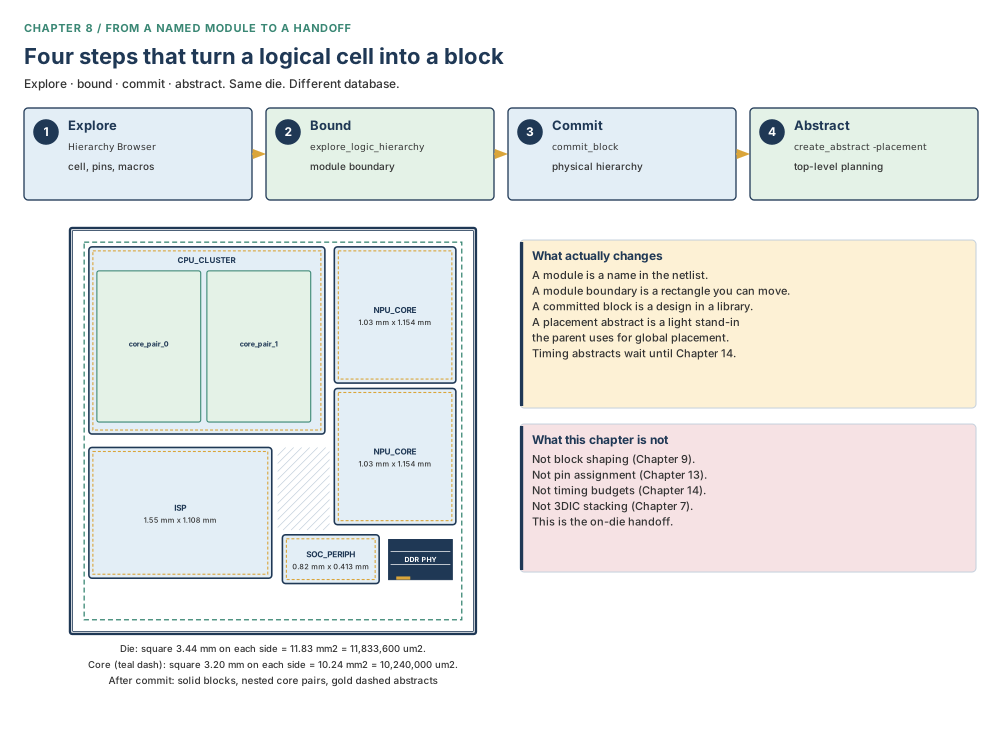
-nested. Gold dashed insets are placement abstracts. Timing abstracts, pin assignment, and block shaping are later chapters. Teaching purpose: one picture of the whole job before any command is typed.The beginner’s mental model
A named floor is not yet a locked flat
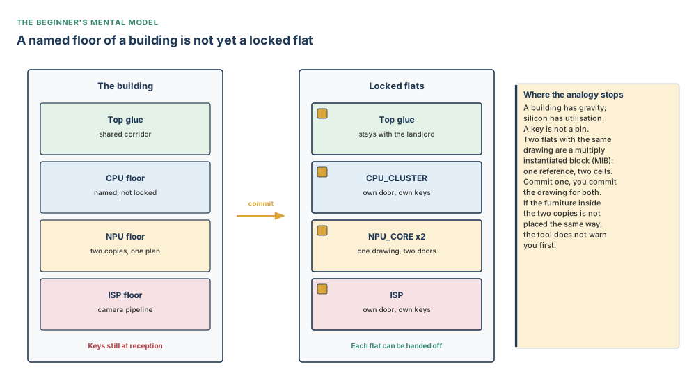
Imagine an office building whose directory lists “CPU floor”, “NPU floor”, “ISP floor”. Those names tell a visitor where to walk. They do not give anyone a key, a lease, or a door that closes. Until Facilities converts a named floor into a locked flat, the furniture can still be shuffled into the corridor, and you cannot hand the floor to a tenant.
A logical module is the name on the directory. A module boundary is a piece of tape on the floor, sized from how densely you intend to pack. A committed block is the locked flat: it has a door (the boundary), a coordinate system (the origin), a keep-out at the walls, and a place in a library you can give to somebody else. A placement abstract is the fire-escape plan you pin in the lobby so the rest of the building can be designed without walking through every room.
The precise engineering model
The design database holds a logical hierarchy: cells that instantiate other cells, ending in standard cells and hard macros. None of that is a physical partition. A module boundary is a planning object attached to a logical cell. Its area is, by default, the cell’s content divided by the utilisation of the top-level floorplan. You can move it, nest it, group it, or throw it away. The netlist does not change.
commit_block turns a logical cell into a physical hierarchy block: a separate design, written to a library you name (or to the current design library). The GUI then shows outline views of those designs. What the new block looks like depends on whether the cell’s hierarchy type was module boundary or plain module. That fork is not a preference. It is the difference between a block that sits in the core with its cells placed, and a default square parked outside the core with its cells unplaced.
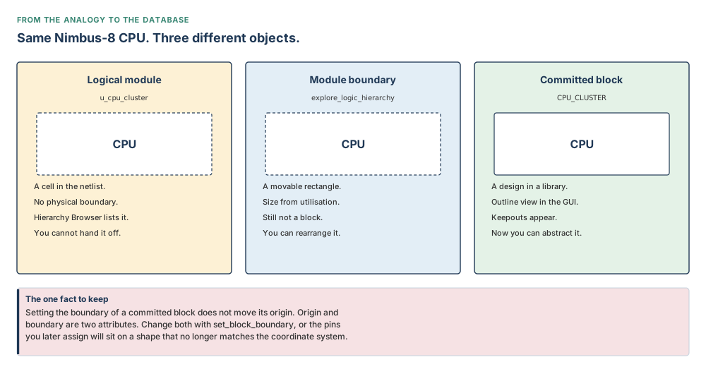
Sit with those three objects before you type. The name in the netlist does not know about millimetres. The tape on the floor does not live in a library. The locked flat does. If you treat the GUI rectangle as all three, you will commit the wrong thing and then wonder why the command “worked”.
A placement abstract is a third representation of the same block. It keeps the hard macros, remembers the original standard-cell count and area, and keeps enough standard cells and registers to represent the I/O interfaces. It does not keep the timing graph. That is a different abstract, taught in Chapter 14. Chapter 5’s black-box abstract is different again: it stands in for logic you do not have yet.
Do not confuse these
| This | Is not this | Why the mix-up is expensive |
|---|---|---|
| Module | Block | A module is logical. A block is physical, after commit. Planning a module’s utilisation is not handing it off. |
| Module boundary | Committed boundary | The first is tape. The second is the block’s shape, with keepouts, origin and site arrays. |
| Outline view | Design view | current_design reporting .outline means the Verilog has not been expanded. Abstracts built from that are the wrong object. |
| Placement abstract | Timing abstract | -placement does not trace paths to ports. Timing levels (boundary, compact, full_interface) are Chapter 14. |
| Placement abstract | Black-box abstract (Ch. 5) | A black box stands in for missing logic. A placement abstract stands in for a block you already committed. |
| Boundary attribute | Origin attribute | Reshaping the outline does not move the origin. Pins you assign later sit in the old coordinate system. |
| Push-down of routing | Push-down of a cell tree | push_down_objects cannot push an OR-gate tree. That is write_push_down_eco. |
| Electrically equivalent port | Feedthrough port | Default push creates the first. A feedthrough needs create_pin_constraint ... -allow_feedthroughs true. |
| Shadow netlist | Front-end netlist | write_verilog includes shadows by default. A synthesis netlist often should not see them. |
Concepts built from first principles
Part 1 — Explore the hierarchy you actually have
Open View > Hierarchy Browser. Each row is a cell. Sit with the columns before you invent a partition:
- Cell name — the folder in the netlist. Still a name, not a rectangle.
- Utilisation — how full that folder would be if you drew a box around everything beneath it, using the area you have not drawn yet. A healthy colour here can hide a child that will not fit.
- Pin count — how many wires must leave the box. That is tomorrow’s channel demand.
- Hard macros — SRAMs and PHYs. They do not fold. They dictate the box more than standard cells do.
- Standard cells in the entire hierarchy — the number that must later sit inside the keepouts, not just in this level of the folder.
Expand and collapse. Rearrange columns. Click a block name to select it in the layout. This is a census, not a floorplan. Census first.
You are about to invent physical partitions. The Hierarchy Browser is the cheapest way to see whether a candidate is a block or a folder of leftovers. Pin count predicts channel demand. Hard-macro count predicts whether the rectangle is a sea of standard cells or a parking lot of SRAMs. Standard-cell count through the entire hierarchy is the number that will later have to fit inside the keepouts.
Part 2 — Draw a module boundary before you commit
A module boundary is how you try a partition on for size without changing the netlist. The command is explore_logic_hierarchy. The option that creates the rectangles is -create_module_boundary.
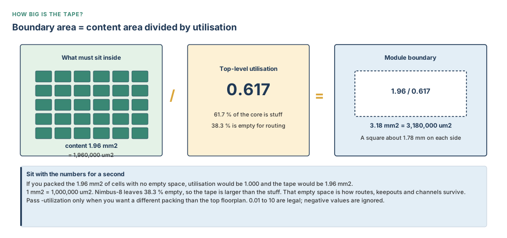
Default size uses the utilisation of the top-level floorplan. Nimbus-8’s core is a square 3.20 mm on each side, so an area of 10.24 mm² = 10,240,000 µm², at utilisation 0.617. That 0.617 means: of every 1,000 µm² of core, 617 µm² is allowed to hold cells and macros, and 383 µm² is left empty so routes can breathe.
Walk one example slowly. A module whose contents occupy 1.96 mm² = 1,960,000 µm² receives a boundary of 1.96 ÷ 0.617 ≈ 3.18 mm² = 3,180,000 µm² unless you pass -utilization. A square of that area is about 1.78 mm = 1,780 µm on each side. You can still drag it into a rectangle that is not square. Valid utilisation values are between 0.01 and 10. A value less than zero is ignored and the design utilisation is used.
Without -cell, -create_module_boundary removes every existing module boundary and rebuilds them for all top-level logical hierarchies, ignoring any hierarchy smaller than the threshold. The default threshold is 0.03 — three per cent of total size — and is also stored in plan.explore.default_threshold. On Nimbus-8 that is 3 per cent of 10.24 mm² = 0.307 mm² = 307,000 µm². A wrapper smaller than that vanishes without a row in the log you will remember. If the threshold is negative the tool warns and uses zero. If you name cells with -cell, the threshold is ignored: you asked for those cells by name.
# Nimbus-8: tape on the floor for the four top-level candidates
icc2_shell> explore_logic_hierarchy -create_module_boundary \
    -cell {u_cpu_cluster u_npu_core_0 u_isp u_soc_periph}
# keep the parent, add a child inside it
icc2_shell> explore_logic_hierarchy -create_module_boundary -nested \
    -cell {u_cpu_cluster/u_core_pair_0 u_cpu_cluster/u_core_pair_1}
After creation the layout typically shows the original floorplan, I/Os above it, unplaced macros above the module boundaries, and the new rectangles themselves piled toward the lower right. Sit with that pile. You have not placed anything. You have taped names. Use the GUI assistants (View > Assistants > Hierarchy Exploration, or Floorplan Preparation > Hierarchy Exploration in the Task Assistant) and the context-menu item Create Module Boundary when you want to do the same thing with a mouse.
-organize moves those rectangles, the unplaced macros, and the unplaced pads back into three predefined regions, and resets the boundaries to rectangles after you have been dragging them. -remove deletes all module boundaries, or only those named with -cell. Macros from a removed boundary are placed to the upper-right of the design boundary.
By default nested boundaries are not allowed: you cannot create A and A/B in one breath. -nested keeps the parent and adds the child. -expand removes a parent boundary and builds children that pass the threshold. -collapse does the reverse. -place tries to pack boundaries into the floorplan; committed blocks and boundaries marked fixed stay put. Add -rectangular if you must forbid rectilinear shapes. Without it, -place may create non-rectangular boundaries to reduce overlap. -use_existing_placement is valid only with -place.
You omit -cell on a real netlist? Every top-level hierarchy larger than three per cent of the design is taped. Tiny wrappers vanish without a row in the log you will remember. That is not a failure. It is the threshold doing its job, and it is the usual reason a candidate “never got a boundary”.
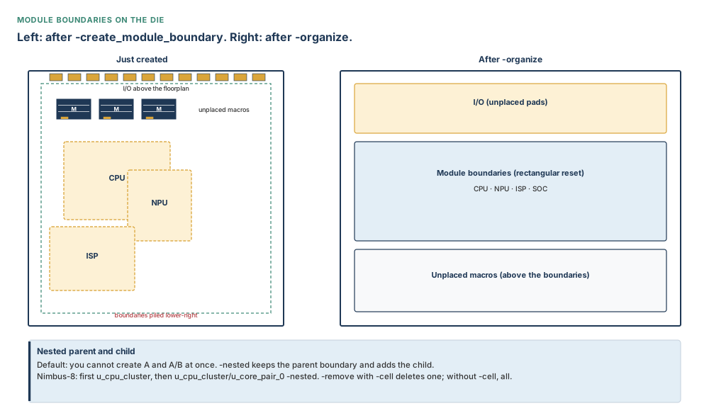
-organize sorts the pile into three regions so you can start placing. Nested children need -nested on purpose. Teaching purpose: show the GUI layout the command actually produces, not a tidy textbook floorplan.Flat designs: virtual hierarchies and move bounds
Some netlists arrive already flattened. Names remain — u_cpu_cluster_alu_0 and so on — but there is no logical cell to attach a module boundary to. Set plan.place.hierarchy_by_name to true. The same command then extracts virtual hierarchies by name and creates move bounds. Existing module boundaries are removed first.
# flattened netlist: one bound per named virtual hierarchy
icc2_shell> set_app_options -list {plan.place.hierarchy_by_name true}
icc2_shell> explore_logic_hierarchy -create_module_boundary -cell {modA}
# or one bound that groups several modules
icc2_shell> explore_logic_hierarchy -name group1 -virtual_group {modA modB}
icc2_shell> get_attribute [get_bounds group1] -name flat_hier_names
-virtual_group must be paired with -name. The members need not share a logical parent. Report them with flat_hier_names on the bound. This is still not a commit. It is tape with a different backing.
Part 3 — Commit: the moment a module becomes a block
This is the lock. Until now you were taping names. Optional, but this is how a block is distributed to another engineer: create a library, save it, add it as a reference, then commit into it.
# optional distribution library, then commit the CPU reference
icc2_shell> create_lib cpu_cluster.dlib
icc2_shell> save_lib cpu_cluster.dlib
icc2_shell> set_ref_libs -add cpu_cluster.dlib
icc2_shell> commit_block -library cpu_cluster.dlib CPU_CLUSTER
Without -library, the new design is created in the current design library. -library must name the design library or one of the current reference libraries. -cells and the module-name argument are mutually exclusive: specify one. If you name a reference with -cells, the command commits that module and uses the named cell’s boundary for every MIB instance.
The shape depends on hierarchy type:
- module boundary, placed in the core: the command has a physical boundary and an origin. Member cells are placed in the new reference so that their geometry relative to the block origin matches their geometry relative to the lower-left of the old module boundary. The instance sits on that origin.
- module (no boundary): a default square is invented from leaf-cell and child-block counts. Member cells are left unplaced. The instance is placed outside the top-level core. Site arrays may not align with the top, because there was no overlap; later shaping is expected to repair that.
- module with multiple fixed-placed children: a bounding box of those children is derived, origin at its lower-left, orientation R0. Further MIB instances are placed from a fixed-placed reference child. You must confirm that every MIB copy’s fixed children agree. The command does not pre-check this. Inconsistent copies produce unpredictable rooms.
During commit, routing on module-owned nets is propagated; move bounds enclosed by the module boundary whose cells belong only to that module are propagated; group bounds and relative-placement groups whose members belong exclusively to the module are propagated. Placement blockages and route guides that lie completely inside the module boundary are propagated; without a module boundary, they are not.
If the committed instance overlaps top-level site arrays, copies of those arrays are created in the block. By default a hard inner keepout margin is created, equal to one row height, and a default outer keepout equal to twice the minimum wire-track width. On Nimbus-8 the inner keepout is therefore 0.576 µm — one teaching-library row, about six tenths of a micron. Sit with that stripe: it is paint along the inside of the wall so standard cells cannot sit on the pins. You type it with a unit character, for example 0.576um. Do not convert it to millimetres and drop the unit: the option will not guess. You can change the paint. You cannot pretend it is not there after a default commit. Read the outer keepout back from the block; do not assume it equals twice the M2 pitch of 0.048 µm. Control both with:
# sizes need a unit character: 0.3um, not a bare 0.3
icc2_shell> set_app_options -list {plan.commit.inner_keepout_margin hard}
icc2_shell> set_app_options -list {plan.commit.inner_keepout_margin_size 0.3um}
icc2_shell> set_app_options -list {plan.commit.outer_keepout_margin hard}
icc2_shell> set_app_options -list {plan.commit.outer_keepout_margin_size 0.1um}
# or suppress both
icc2_shell> set_app_options -list {plan.commit.inner_keepout_margin none}
icc2_shell> set_app_options -list {plan.commit.outer_keepout_margin none}
Distance values must include a unit character. These application options persist in the database. If the parent has SAIF map data, the committed block loads a block-level SAIF map from it.
The command fails if the library is not the design library or a current reference library; if the module does not exist or is not a hierarchical logic cell; or if the library already contains a design of that name. Reverse a commit with uncommit_block — confirm the options on your build with man uncommit_block before you rely on a flag.
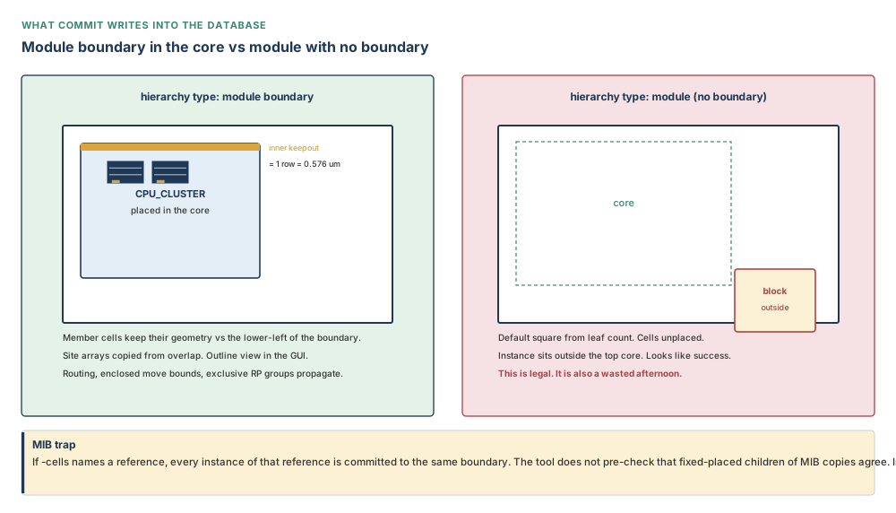
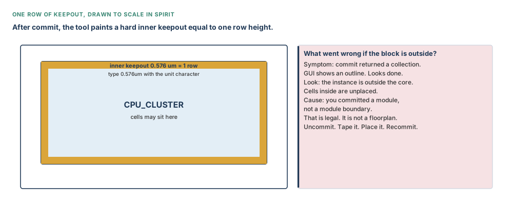
commit_block returns a collection of committed cells. That return value means the write succeeded, not that the block is in the core with its cells placed. Look at the instance. If it is outside the core, you committed a module, not a module boundary.
Part 4 — Placement abstracts: a light stand-in for the parent
After commit, the parent still sees full blocks unless you replace them with abstracts. A placement abstract is the stand-in this chapter owns. Prerequisite: load the full netlist of the top level, without the details of the committed children. If current_design reports lib:BLOCK.outline rather than .design, expand first.
# mapping file from split_constraints (Chapter 3)
icc2_shell> set_constraint_mapping_file split/mapfile
icc2_shell> sh cat split/mapfile
# Verilog must still sit at the path read_verilog_outline used, or on search_path
icc2_shell> expand_outline
icc2_shell> save_lib -all
icc2_shell> set_host_options -name block_script ...
icc2_shell> check_host_options -host_options block_script -target ICC2
icc2_shell> create_abstract -placement -host_options block_script -all_blocks
Omit -host_options to run locally. Use -blocks {list} instead of -all_blocks for a subset. The two are mutually exclusive. With neither, the command abstracts the current design. -work_dir holds generated scripts and logs; default is the host option’s directory, or ./work_dir. -force_recreate rebuilds an abstract of the same type; without it, an existing abstract of the requested type is left alone. -placement always produces an editable abstract and overrides -read_only.
In a multi-level physical hierarchy, only one level of physical hierarchy can be an abstract view at a time. By default -all_blocks abstracts the lowest-level block that is allowed to have an abstract. abstract.allow_all_level_abstract true lets you abstract a child at any level if that child’s plan.flow.design_view_only is false. False (the planning default) means only the lowest-level block with plan.flow.design_view_only false. -target_use planning applies that rule; -target_use implementation allows abstract creation at any physical-hierarchy level. -preserve_block_instances defaults to true; false flattens nested physical hierarchy into the abstract.
The readiness gate is check_design -checks {dp_pre_create_placement_abstract}: the mapping file has UPF for all blocks, and outline netlists are in place. The Verilog files expand_outline rereads must still be at the original read_verilog_outline path, or on search_path. -force rereads even if they look unchanged; use it with care, because modules are found by the original line numbers. Insert a comment, and expansion can fail. -keep retains the outline in memory. -no_def skips DEF during expansion. -strip removes path prefixes when searching.
All leaf cells of a block must be mapped before abstract creation. The command also saves the current block to disk.
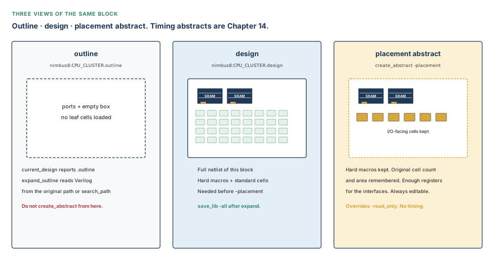
CPU_CLUSTER. Abstracts need the middle column. The left column is a silhouette. The right column is what the parent should plan against. Teaching purpose: connect current_design’s .outline/.design suffix to a picture of what is loaded.Top-level global placement needs connectivity and area, not nine million standard-cell shapes. A placement abstract is that compromise. Using it for timing closure is a category error: there is no timing graph. Using a black-box abstract here is the other category error: you do have the logic; you committed it.
create_abstract -placement. An abstract built on an outline is a silhouette of a silhouette.Part 5 — Boundary and origin are two attributes
Editing a committed block’s outline in the GUI writes the boundary attribute. It does not write origin. The pins, the keepouts and every child coordinate still speak the old origin. The command that writes both is:
# teaching L-shape; every number is micrometres
# 50 um = 0.050 mm. This is not the Nimbus-8 CPU size.
icc2_shell> set_block_boundary -cell u_cpu_cluster \
    -boundary {{50 50} {300 50} {300 200} {150 200} {150 300} {50 300}} \
    -origin {50 50} -orientation R0
-boundary is a polyrect: a list of coordinates in the current design. Table 8.1 still holds: you type micrometres. Sit with the two attributes. The outline is the wall. The origin is the (0, 0) of every pin, keepout and child that will be written later. If you omit -origin, origin is derived from orientation: R0 uses the lower-left of the bounding box; MX uses the upper-left; and so on. Message DPP-057 confirms the write.
move_block_origin -to {500 500} is a different job. It moves the current top-level origin relative to the current origin. On a square 1,000 µm = 1.000 mm on each side whose origin is (0, 0), so an area of 1.00 mm² = 1,000,000 µm², -to {500 500} places the origin at the centre. It does not reshape a child.
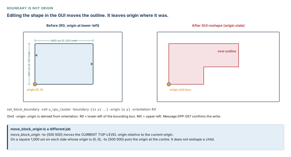
set_block_boundary and an explicit origin. A GUI outline is only half the write.Part 6 — Push down, pop up, and the shadow netlist
Objects you drew at the top — PG straps, signal routes, guides, blockages, bump regions — often belong inside a child once the child exists. Sit with the sequence before you type it: set the options, report them so you can see what you set, optionally check, then push. Skipping the report is how a clean check of the wrong options becomes a wasted afternoon.
icc2_shell> set_push_down_object_options \
    -object_type {pg_routing signal_routing} \
    -top_action remove \
    -block_action {copy create_pin_shape}
icc2_shell> report_push_down_object_options
icc2_shell> check_objects_for_push_down
icc2_shell> push_down_objects
Object types: pg_routing, signal_routing, routing_guide, routing_corridor, blockage, pin_guide, pin_blockage, cells, charging_station, bump_region, marker_layer. Top actions: keep or remove. Block actions depend on type: center_pin_from_wire, copy, create_blockage, create_pin_shape, create_route_blockage_from_cell, retain_obsolete_ports. For PG routing, copy, create_blockage and center_pin_from_wire are mutually exclusive; create_pin_shape may combine with the others. Default block action for PG routing is create_pin_shape. center_pin_from_wire makes a pin from any wire in the interior — use it on a limited set, then turn it off.
Other options: -routing_overlap_check; -ignore_misalignment (MIB PG); -allow_multi_rail_cells; -collinear_margin (PG only; default −1, overlapping parallels only; 0 means abutting; greater than zero copies parallels within that distance into the child and leaves the original at the top); -pin_meet_fatwire_rule; -location_based_terminal_naming; -create_pg_feedthrough. Confirm current defaults with report_push_down_object_options and man set_push_down_object_options.
Pushed objects are named with suffix _PUSHDOWN_n unless you set plan.pins.new_port_name_tag (ports and nets) or plan.pins.new_cell_name_tag (cells). After a push, is_shadow is true and shadow_status is pushed_down. Other status values: copied_down, copied_up, normal, pulled_up, virtual_flat. Feedthroughs that were pushed down tag the pins, nets and buffers.
check_objects_for_push_down looks at collinear routes and vias, physical routing incompatible with a logical net, incomplete top-level routing, and charging stations for UPF. It uses the options you just set. Zero problems with default options is not zero problems with the options you meant to set. The readiness gate dp_pre_push_down is the MIB alignment check.
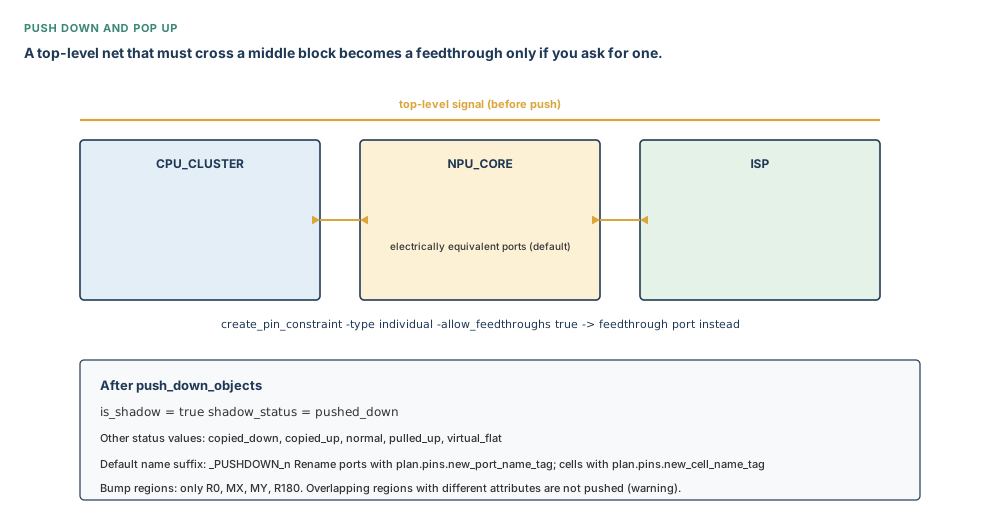
Bump regions, feedthroughs, and a via as a pin
Pushing a bump region recalculates boundary, pattern offset, orientation, pitches and staggers so the region looks the same from the top; cuts overlapping block boundaries; checks MIB alignment; refuses overlapping regions that have different attributes (warning, not pushed); and maps TSV information onto pseudo bumps. After the push the net matrix is kept or mapped, and top regions stay anchored. Allowed orientations: R0, MX, MY, R180 only.
Default push of a signal creates an electrically equivalent port on the lower block. To create a feedthrough port instead:
icc2_shell> create_pin_constraint -type individual \
    -nets [get_nets * -filter "net_type == signal"] \
    -allow_feedthroughs true
Full pin-constraint teaching is Chapter 13; this chapter needs only that option. A routing corridor’s nets, pushed down, produce a pure feedthrough in a middle block and physical pins where a detailed route meets a boundary.
Pins default to block edges. To use a via as the pin location (which limits pin count on MIBs), set block actions to {copy create_pin_shape} and push the via:
icc2_shell> push_down_objects [get_vias VIA_S_5] -cells {u1 u2}
Pop up
The reverse sequence: set_pop_up_object_options, report_pop_up_object_options, pop_up_objects. Same object types. Block action is keep or remove. -routing_overlap_check applies to PG and signal. -pins_as_terminals creates top-level terminals. After a pull-up, shadow_status is pulled_up.
Child bump regions become separate top regions, not merged. Geometry is recalculated; TSV mapping is copied. Keep leaves the original; remove deletes the child. Top action for bump regions is only copy. Shadow status is copied_up or pulled_up according to the block action.
Part 7 — When the netlist must move, not the geometry
push_down_objects moves physical objects. Three ECO commands move netlist structure the push cannot touch.
write_split_net_eco pushes the branching of a physical multiple-fanout net — a net that connects more than one physical block — as high in the hierarchy as it can go, including through logic wrappers. Default: all such nets. -nets selects. -filename writes a file; without it, the script prints to the console. source the file to apply it.
write_push_down_eco pushes a tree of standard cells (an OR-gate tree is the teaching case) one physical level. The tree must completely fit in the block. New ports are created; original ports are not reused; unused inputs are tied to VSS. One ECO file per block; default directory push_down_eco_scripts; -dir overrides. Source the top-level Tcl.
write_spare_ports_eco creates spare or dummy feedthrough ports and the top-level nets that connect them. Specify the cell_list. -name defaults to dummyFT. -direction is in, out or inout, and is required. -bits is a start index and an end index, both non-negative: {0 4} is bits 0, 1, 2, 3 and 4 — five bits. Default directory create_spare_ports. Source the top-level script; it calls the others.
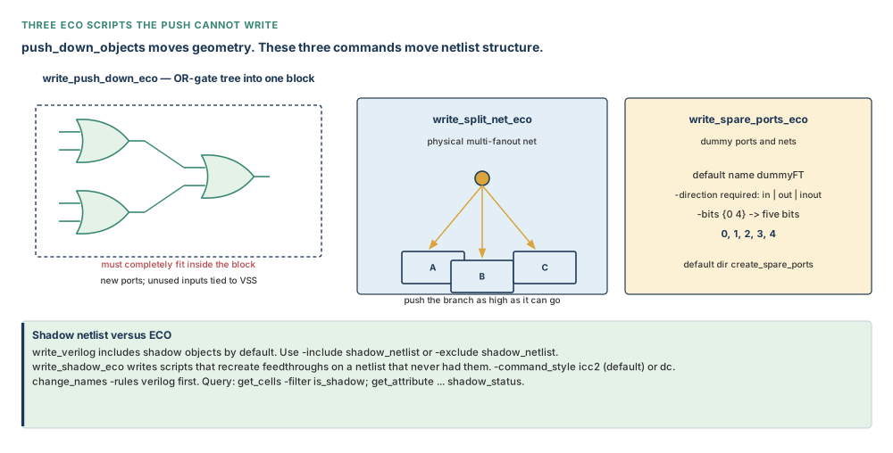
write_verilog includes shadow objects by default. Use -include shadow_netlist or -exclude shadow_netlist when you mean it. To give a front-end the feedthroughs without the shadow attributes, run change_names -rules verilog then write_shadow_eco. -command_style icc2 is the default; dc writes a flavour a synthesis session can consume — and will error if net and port names were allowed to diverge. Query:
icc2_shell> open_block
icc2_shell> get_cells -filter is_shadow
icc2_shell> get_nets -filter is_shadow
icc2_shell> get_attribute [get_nets * -filter is_shadow] shadow_status
Inputs, outputs, and readiness
| Stage | Needs | Writes |
|---|---|---|
| Explore | A linked design with a floorplan utilisation | Nothing persistent. A census. |
| Module boundaries | Named logical cells, or plan.place.hierarchy_by_name on a flat netlist | Planning rectangles (or move bounds). Netlist unchanged. |
| Commit | A hierarchical logic cell; preferably a module boundary in the core; a library that does not already hold that design name | A physical block in a library; keepouts; propagated routing and bounds; outline views in the GUI. |
| Expand | Verilog still at the original path or on search_path | A .design representation. Outline closed unless -keep. |
| Placement abstract | Full top netlist, mapping file, mapped leaf cells, host options if distributed | An editable placement abstract; parent switched onto it; block saved. |
| Push / pop | Options set and reported; MIB alignment for bump regions | Child geometry; shadow attributes; optional top removal. |
| ECO scripts | The structure that actually exists (fanout, tree, or spare) | Tcl under the stated directory. Nothing changes until you source it. |
Preflight checklist
- Hierarchy Browser: every candidate has a pin count and a hard-macro count you believe.
- Top-level utilisation is the utilisation you want the boundaries sized from, or you will pass
-utilization. - MIB copies: fixed-placed children agree, because commit will not check.
- Target library exists, is a reference library, and does not already contain the new design name.
split_constraintsmapping file lists UPF for every block you will abstract.- Verilog files have not moved, and have not gained a comment that shifted line numbers, unless you intend
expand_outline -force. current_designreports.designbeforecreate_abstract -placement.check_design -checks {dp_pre_create_placement_abstract}is clean, thendp_pre_push_downbefore a bump-region push.
A module boundary sized from a stale utilisation. A commit of a bare module that “succeeds” outside the core. An abstract created while current_design still says .outline. A push-down check that reports zero because the options were never set. A write_verilog the front-end accepts that still contains every shadow object. None of these are crashes. All of them are the wrong database.
Guided tool workflow
Numbered path from a linked Nimbus-8 floorplan to a parent that plans against placement abstracts, with the objects that belong in the children pushed down.
- Census: Hierarchy Browser. Record utilisation, pins, macros, standard cells for
u_cpu_cluster,u_npu_core_0,u_isp,u_soc_periph. - Tape:
explore_logic_hierarchy -create_module_boundary -cell {...}, then nested core pairs with-nested. Drag into the core.-organizeif the pile takes over. - Commit each reference into its library (or the current design library). Confirm each instance sits in the core and that cells inside are placed.
- Point at the mapping file.
expand_outlineif needed.save_lib -all. - Gate:
check_design -checks {dp_pre_create_placement_abstract}. create_abstract -placement -all_blocks(distributed or local).- If a child’s outline is wrong,
set_block_boundarywith origin and orientation. Confirm DPP-057. - Set push-down options, report,
check_objects_for_push_down,push_down_objects. Queryis_shadow. - Where the structure is a tree, a multi-block fanout, or a spare port, write the matching ECO and
sourceit.
Eight-point treatment of the commands that matter
For every important command: purpose, syntax, prerequisites, a small example, expected result, verification, common mistakes, and how to discover more. Additional options: man <command> and help <command>, as in Chapter 2. Do not invent flags from memory.
| Command | The eight points |
|---|---|
| explore_logic_hierarchy |
|
| commit_block |
|
| expand_outline |
|
| create_abstract |
|
| set_block_boundary |
|
| move_block_origin |
|
| set_push_down_object_options / push_down_objects |
|
| write_split_net_eco / write_push_down_eco / write_spare_ports_eco |
|
One continuous worked example — Nimbus-8
Situation. The floorplan from Chapter 4 is still one physical design. The four named regions are modules. Two NPU instances share one reference. The CPU cluster has two core pairs you intend to keep nested. You must produce libraries the block owners can take, and a top level that can be planned against placement abstracts.
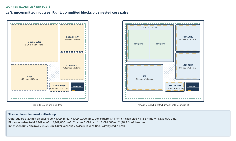
Initial conditions. Library nimbus8.dlib, top NIMBUS8. Core a square 3.20 mm on each side, so 10.24 mm² = 10,240,000 µm², utilisation 0.617. Die a square 3.44 mm on each side, so 11.83 mm² = 11,833,600 µm². Block-boundary total we are aiming at: 8.149 mm² = 8,149,000 µm²; channel 2.091 mm² = 2,091,000 µm² (20.4 per cent of the core). Row height 0.576 µm. Mapping file from Chapter 3 at split/mapfile.
# 1. tape the four top-level candidates, then nest the core pairs
icc2_shell> explore_logic_hierarchy -create_module_boundary -cell \
    {u_cpu_cluster u_npu_core_0 u_isp u_soc_periph}
icc2_shell> explore_logic_hierarchy -create_module_boundary -nested -cell \
    {u_cpu_cluster/u_core_pair_0 u_cpu_cluster/u_core_pair_1}
# drag into the core; NPU instance 1 shares the NPU_CORE drawing
icc2_shell> explore_logic_hierarchy -organize
Place the CPU boundary at 2.00 mm × 1.586 mm = 3.172 mm² = 3,172,000 µm², the NPU at 1.03 mm × 1.154 mm = 1.189 mm² = 1,189,000 µm² (both instances), the ISP at 1.55 mm × 1.108 mm = 1.717 mm² = 1,717,000 µm², the SoC periphery at 0.82 mm × 0.413 mm = 0.339 mm² = 339,000 µm². The block-boundary total we are aiming at remains 8.149 mm² = 8,149,000 µm²; the leftover channel is 2.091 mm² = 2,091,000 µm². Confirm the two NPU rectangles are congruent. If they are not, stop: commit will not fix furniture that already disagrees.
# 2. commit references. NPU is one MIB reference, two cells.
icc2_shell> commit_block -library nimbus8.dlib CPU_CLUSTER
icc2_shell> commit_block -library nimbus8.dlib NPU_CORE
icc2_shell> commit_block -library nimbus8.dlib ISP
icc2_shell> commit_block -library nimbus8.dlib SOC_PERIPH
Expected: four outline views. Each instance in the core. Inner keepout 0.576 µm. Member cells placed, because these were module boundaries. The two NPU cells share one reference. Nested core pairs remain children of CPU_CLUSTER if you committed the parent with those boundaries present; if you needed them as their own physical blocks, commit the children before abstracting the parent, and read abstract.allow_all_level_abstract before you abstract a mid-level block.
# 3. full top netlist, then placement abstracts
icc2_shell> set_constraint_mapping_file split/mapfile
icc2_shell> current_design
# if the reply contains .outline:
icc2_shell> expand_outline
icc2_shell> save_lib -all
icc2_shell> check_design -checks {dp_pre_create_placement_abstract}
icc2_shell> create_abstract -placement -all_blocks
Interpret the abstract: hard macros remain; most standard cells vanish; interface registers remain; the parent’s global placer now sees area and connectivity, not nine million shapes. This is an estimate of congestion, not a signoff.
# 4. a child outline that must become rectilinear, origin included
# 1550 um = 1.550 mm; 1108 um = 1.108 mm. Same ISP you just placed.
icc2_shell> set_block_boundary -cell u_isp \
    -boundary {{0 0} {1550 0} {1550 1108} {0 1108}} \
    -origin {0 0} -orientation R0
# 5. push PG and signal routing that already exists at the top
icc2_shell> set_push_down_object_options -object_type {pg_routing} \
    -top_action keep -block_action {copy create_pin_shape}
icc2_shell> report_push_down_object_options
icc2_shell> check_design -checks {dp_pre_push_down}
icc2_shell> check_objects_for_push_down
icc2_shell> push_down_objects
icc2_shell> get_nets -filter is_shadow
Engineering judgement — what a senior engineer inspects next. Not the log. The instances: in the core, congruent MIBs, keepouts present. Then current_design’s suffix. Then whether the abstract still shows every SRAM you counted in the Hierarchy Browser. Then whether the front-end has asked for a shadow ECO or a clean Verilog. Then, and only then, Chapter 9’s question: are these rectangles the right shape?
Failure modes and debugging
Major-chapter bar: ten realistic mistakes, including one misleading symptom. Warnings are not hard errors. A poor-quality-but-legal result is the usual failure mode in this chapter.
| Symptom | Likely cause | Check | Correction | Prevention |
|---|---|---|---|---|
| Candidate never got a boundary | Default 0.03 threshold, and you omitted -cell | Size against 3 per cent of the design | Name it with -cell, or lower plan.explore.default_threshold | Always name the cells you mean |
| Nested child refused | -nested omitted | Parent already has a boundary | Rerun with -nested | Treat nesting as opt-in |
| Commit “worked”; block sits outside the core, cells unplaced | Hierarchy type was module, not module boundary | Is the instance outside the core? | uncommit_block, create a boundary in the core, recommit | Never commit tape you have not placed |
| MIB instances look different after commit | Fixed-placed children disagreed; no pre-check | Compare child origins before commit | Uncommit, align furniture, recommit from one reference | Congruence check is yours |
| Library already contains that design | Name collision | List designs in the target library | New library, or remove the stale design on purpose | One reference name per drawing |
| Abstract looks empty | current_design was still .outline, or Verilog moved | current_design; search_path | expand_outline, then recreate with -force_recreate | Gate on dp_pre_create_placement_abstract |
expand_outline fails after a “harmless” edit | Line numbers moved; -force cannot invent modules | Diff the Verilog against the outline’s recorded lines | Restore the file, or re-read the outline from scratch | Do not comment a netlist the outline still points at |
| Push-down check is clean, PG is wrong in the child | Options never set; check used defaults | report_push_down_object_options | Set, report, recheck, push | No check before a report |
| Bump region not pushed, warning only | Orientation not in {R0, MX, MY, R180}, or overlapping regions with different attributes | Region orientation and attributes | Fix orientation or attributes, push again | Treat the warning as a skip, not a success |
| Front-end rejects nets that “exist” | write_verilog included shadows, or net/port names diverged for -command_style dc | get_nets -filter is_shadow | write_verilog -exclude shadow_netlist or write_shadow_eco -command_style dc after change_names -rules verilog | Ask which file the front-end is actually going to read |
| OR-tree still at the top after a push | push_down_objects cannot move that tree | Do the cells completely fit in the child? | write_push_down_eco, then source | Geometry push versus netlist ECO is a classification, not a retry |
| Pins sit off the new outline | GUI reshaped boundary, left origin | Report both attributes | set_block_boundary with -origin | Never reshape without origin |
The rose row is the misleading symptom. The apparent cause is “commit failed to place the block”. The real cause is that you never gave it a boundary to place. The command did exactly what a bare module is specified to do.
Hard errors: missing module, library name collision, library not a reference. Warnings: skipped bump regions, threshold replacements. Poor-quality-but-legal: everything else in that table.
Hands-on mini lab — Orion-5
Goal. On a tiny synthetic die, create one module boundary, commit it, expand if needed, build a placement abstract, and prove the origin survived a reshape.
Supplied assumptions. Core a square 1,200 µm = 1.200 mm on each side, so 1.44 mm² = 1,440,000 µm². Utilisation 0.70. Two logical cells: u_core (placeable content 0.490 mm² = 490,000 µm²) and u_glue (stays at the top). Teaching row height 0.576 µm. Verilog at orion5.v, mapping file split/mapfile. No proprietary data.
Steps.
- Compute the default module-boundary area for
u_core: 0.490 ÷ 0.70 = 0.700 mm² = 700,000 µm². Side of a square: √700,000 ≈ 836.7 µm = 0.837 mm. explore_logic_hierarchy -create_module_boundary -cell {u_core}. Place that rectangle in the core.commit_block ORION5_CORE(or-libraryof your design library). Confirm the instance is inside the core and the inner keepout is one row, 0.576 µm.current_design. If the suffix is.outline,expand_outlinethensave_lib -all.set_constraint_mapping_file split/mapfilethencheck_design -checks {dp_pre_create_placement_abstract}thencreate_abstract -placement.- Reshape with
set_block_boundary -cell u_core -boundary {{0 0} {900 0} {900 780} {0 780}} -origin {0 0} -orientation R0. Those numbers are micrometres: 900 µm = 0.900 mm, 780 µm = 0.780 mm, so an area of 0.702 mm² = 702,000 µm² — a hair larger than the 0.700 mm² default square, and rectangular on purpose. Confirm DPP-057. Report origin: it must still be (0, 0), not a stale corner from a GUI drag.
Expected observations. Boundary area before commit near 0.700 mm² = 700,000 µm². After commit, instance in the core, cells placed, keepout 0.576 µm. Abstract retains macros and interface cells. Origin matches the lower-left of the new 900 µm × 780 µm = 0.900 mm × 0.780 mm rectangle.
Verification checklist. Instance inside core; .design before abstract; mapping file set; DPP-057; origin report; get_cells -filter is_shadow empty until you push.
Stretch. Add a second instance of the same reference. Mis-place one child’s dummy macro on purpose, commit, and write down what each instance looks like. Then uncommit and explain why the tool was allowed to do that.
Interview preparation
1. What is the difference between a module and a block?
A module is a logical hierarchy cell. A block is a physical hierarchy design, created by commit_block.
The directory name versus the locked flat. Until commit, there is nothing to hand off, abstract, or shape.
2. Where does a module boundary’s default size come from?
The utilisation of the top-level floorplan. Override with -utilization (0.01 to 10). Negative values fall back to design utilisation.
Nimbus-8 at 0.617. Content 1.96 mm² = 1,960,000 µm² becomes about 3.18 mm² = 3,180,000 µm² of tape.
3. What does the default 0.03 threshold do?
Without -cell, hierarchies smaller than 3 per cent of total size are ignored when creating or expanding boundaries. Named cells ignore it.
plan.explore.default_threshold holds the default. Negative input is warned and replaced by zero.
4. What does current_design reporting lib:CPU_CLUSTER.outline mean for create_abstract?
You have a silhouette. expand_outline first, then abstract. Placement abstracts need the full top netlist.
The Verilog must still be at the read_verilog_outline path or on search_path.
5. Inner keepout after commit: what is the default, on Nimbus-8?
A hard inner keepout equal to one row height: 0.576 µm. Outer keepout is twice the minimum wire-track width; read it back.
plan.commit.inner_keepout_margin and _size override it. Values persist.
6. Name the four steps of this chapter, in order.
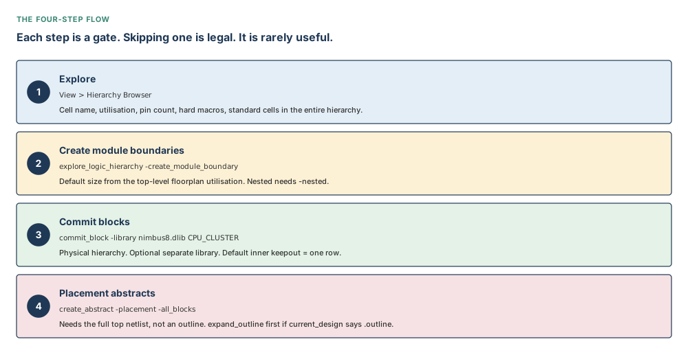
Explore hierarchy; create module boundaries; commit blocks; create placement abstracts.
Each step is a gate. Skipping is legal and usually expensive.
7. You commit a module with no boundary. What should you expect to see?
A default square from leaf counts, cells unplaced, instance outside the top core. The command still returns a collection.
This is specified behaviour, not a crash. Site arrays may not align until later shaping.
8. Compare a placement abstract with a Chapter 5 black-box abstract and with a timing abstract.
Placement: stand-in for a committed block, macros plus interface cells, no timing graph, always editable. Black box: stand-in for missing logic. Timing abstract: Chapter 14, traces paths, timing_level compact/full_interface/boundary.
-placement overrides -read_only and sets timing_level none (deprecated name, same idea).
9. Tradeoff: commit every MIB instance from a named -cells reference, versus committing after checking congruence.
Naming a reference applies one boundary to every instance — fast, and wrong if furniture disagrees. The tool does not pre-check. Checking first costs an hour and saves a respin.
dp_pre_push_down is alignment at push time, not at commit time.
10. Tradeoff: keep versus remove as top_action on PG push-down.
keep leaves the top straps in place (parent still sees them); remove deletes them at the top (child owns them). Collinear copies with collinear_margin leave the original at the top even when the child gets a copy.
Quality: IR drop wants continuity; hierarchy wants ownership. Both can be true if you copy and keep.
11. What does abstract.allow_all_level_abstract change?
True: you may abstract a child at any level if that child’s plan.flow.design_view_only is false. False: only the lowest-level block with that flag false. Planning target_use uses the stricter default.
Only one physical-hierarchy level can be an abstract view at a time.
12. What would you do if commit_block returns a collection but the instance is outside the core?
Do not celebrate. Uncommit. Create a module boundary in the core. Confirm hierarchy type. Recommit. Then look at cell placement and keepouts.
The collection means the write succeeded. It does not mean the floorplan did.
13. What would you do if create_abstract -placement finishes in seconds and the parent still looks full of standard cells?
current_design suffix, mapping file, whether -all_blocks saw any eligible child, whether an old abstract of the same type blocked recreation without -force_recreate, whether you abstracted the parent instead of the children.
Seconds can be a cache hit, not a success.
14. What would you do if write_verilog is accepted by the front-end but many nets ‘do not exist’ in a later ECO?
Those nets were shadows, or net and port names diverged. Query is_shadow. Exclude shadows, or write_shadow_eco -command_style dc after change_names -rules verilog.
Two consumers, two files. Ask which file they sourced.
15. A push of bump regions warns and skips one region. The log is otherwise clean. Next action?
Treat the warning as a skip. Check orientation (only R0, MX, MY, R180) and whether overlapping regions have different attributes. Fix, then push that region again. Do not proceed to RDL as if the field were complete.
A clean log plus a skip is an incomplete field.
16. You need an OR-tree inside a child. push_down_objects left it at the top. Why, and what instead?
The push moves geometry, not a standard-cell tree. If the tree completely fits, write_push_down_eco (new ports, unused inputs tied to VSS), then source the top Tcl. If it does not fit, reshape or split first — that is Chapter 9 meeting this chapter.
Classification before retry.
Chapter close
Sign-off checklist for this stage of planning
- Every intended partition is a committed block in a library, sitting in the core, cells placed.
- MIB instances are congruent; you checked, because the tool did not.
- Inner keepout is the keepout you wanted (default one row), not an accident.
current_designis.designwhere you will abstract.- Placement abstracts exist for the children the parent will plan against; SRAMs still visible; timing not claimed.
- Boundary and origin match on every block you reshaped. DPP-057 on file.
- Push-down options were reported before they were checked. Shadows query as expected.
- Front-end file flavour is agreed: shadows in, shadows out, or a shadow ECO.
- ECO scripts that were needed (split, tree, spare) have been sourced, not only written.
- The rectangles are now ready to be shaped. That is the next chapter, not this one.
Key-concept flashcards
Module: logical cell. Block: physical design after commit_block, in a library.
Movable tape. Default area = content ÷ top utilisation. Not a handoff.
Unnamed hierarchies under 3 per cent of total size are ignored. -cell bypasses it.
Default square, cells unplaced, instance outside the core. Legal. Wrong.
One reference, many cells. Commit the drawing once. Congruence is your check.
Default hard, one row height. Nimbus-8: 0.576 µm. Persistent application options.
current_design suffix. Abstracts need .design. expand_outline rereads Verilog by line number.
Macros, original cell count and area, interface cells. No timing graph. Always editable.
Two attributes. GUI reshape writes one. set_block_boundary writes both.
Set options, report, check, push. Shadows: is_shadow, shadow_status, _PUSHDOWN_n.
Default push: equivalent port. Feedthrough: create_pin_constraint -allow_feedthroughs true.
Split a multi-block fanout. Push a fitting cell tree. Create spare dummyFT ports. Then source.
Compact glossary
| Term | Meaning as used in this book |
|---|---|
| Block | A physical hierarchy design produced by commit_block, stored in a library, with origin, boundary and keepouts. |
| Electrically equivalent port | The default port push_down_objects creates on a child where a top net meets the boundary. Not a feedthrough. |
| Feedthrough port | A port that carries a net through a block. Requires -allow_feedthroughs true on an individual pin constraint. |
| Hierarchy Browser | The GUI census of cells: utilisation, pins, hard macros, standard cells in the entire hierarchy. |
| Move bound | On a flattened netlist with plan.place.hierarchy_by_name true, the planning rectangle that stands in for a virtual hierarchy. |
| Module | A logical hierarchy cell. A name. Not a block. |
| Module boundary | A planning rectangle attached to a module, created by explore_logic_hierarchy. |
| Multiply instantiated block (MIB) | One block reference instantiated more than once. One drawing, several cells. |
| Outline view | A representation that holds ports and a silhouette, not the leaf netlist. current_design reports .outline. |
| Placement abstract | A lightweight, always-editable stand-in for a committed block used in top-level global placement. No timing graph. |
| Shadow netlist | Objects created by push, pop or feedthrough insertion, tagged is_shadow with a shadow_status. |
| Shadow status | One of pushed_down, copied_down, copied_up, normal, pulled_up, virtual_flat. |
Five-question self-check
A new design, Pegasus-4. Core a square 800 µm = 0.800 mm on each side, so 0.64 mm² = 640,000 µm², utilisation 0.50. Three logical modules with content 0.200 mm² = 200,000 µm², 0.150 mm² = 150,000 µm² and 0.010 mm² = 10,000 µm². Row height 0.576 µm. You will name only the first two cells if a threshold would drop the third. A later reshape of the first committed block must keep origin at the lower-left of a 500 µm × 400 µm = 0.500 mm × 0.400 mm rectangle.
- Without
-cell, which modules receive a boundary at the default threshold, and why? - With
-cellnaming all three, what boundary area does each module receive at the default utilisation? - You commit the first module after placing its boundary in the core. What inner keepout do you expect, and where should the instance sit?
- You then commit the third module without a boundary. What legal result should you refuse to accept as done?
- Write the
set_block_boundarycommand that makes the first block 500 µm × 400 µm with R0 origin at the lower-left, and say what a GUI-only reshape would get wrong.
Answers.
1. Three per cent of 0.64 mm² is 0.0192 mm² = 19,200 µm². The 0.200 mm² = 200,000 µm² and 0.150 mm² = 150,000 µm² modules are larger; the 0.010 mm² = 10,000 µm² module is smaller and is ignored. The third module “never got a boundary” because of the threshold, not because it is missing from the netlist.
2. Default utilisation 0.50. Areas: 0.200 ÷ 0.50 = 0.400 mm² = 400,000 µm²; 0.150 ÷ 0.50 = 0.300 mm² = 300,000 µm²; 0.010 ÷ 0.50 = 0.020 mm² = 20,000 µm². Naming them with -cell bypasses the threshold, which is why the tiny one now has tape.
3. Inner keepout = one row = 0.576 µm, hard by default. The instance sits in the core on the origin of that module boundary, with member cells placed relative to its lower-left.
4. A default square parked outside the core, cells unplaced, command still returning a collection. That is specified behaviour for hierarchy type module. Uncommit, tape it, place it, recommit.
5. set_block_boundary -cell u_pegasus_a -boundary {{0 0} {500 0} {500 400} {0 400}} -origin {0 0} -orientation R0. Those numbers are micrometres: 500 µm = 0.500 mm, 400 µm = 0.400 mm, so an area of 0.200 mm² = 200,000 µm². A GUI-only reshape would move the outline and leave the origin on the old lower-left, so later pins would not sit on the new edges. Look for DPP-057.
Why Chapter 9 follows
You now have rectangles that are real designs in a library. They are not yet the right rectangles. A committed block can be too square for its SRAMs, too tight on a side that will carry a bus, too generous on a side that will starve the channel. The next chapter takes these blocks and shapes them — constraints, relative placement, keepouts, arrays, channels, grids — without undoing the handoff you just made. Do not shape a module. Shape a block. That is why this chapter had to come first.