CHAPTER NINE
Shaping Blocks and Placing Macros: The Rectangle You Committed Is Not Yet the Room You Need
By the end of this chapter you will be able to constrain the hard macros that must sit inside a committed block; to paint keepouts that travel with those macros; to shape the block so the corridor between rooms is a number, not a hope; to sit the furniture down with create_placement -floorplan; and to tell a quiet legal success from a floorplan you would actually hand to the next engineer.
Why this chapter matters in a real project
Chapter 8 gave you locked flats. Each named module became a physical block in a library, with an origin, a boundary, and a keepout stripe. That was the handoff. It was not the room. A rectangle 2.00 mm × 1.586 mm is a claim about area. It is not yet a claim about where seventy-two SRAMs will sit, or whether the bus from the CPU cluster to the NPU will have a corridor, or whether two copies of the same NPU drawing will still share a grid after you flip one of them.
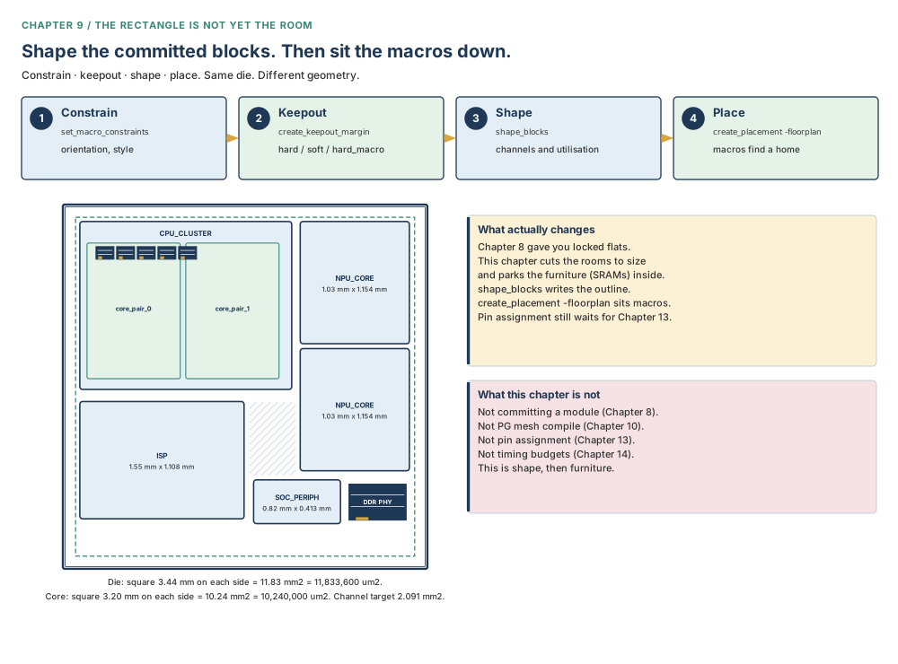
Sit with the die you already know. Nimbus-8’s core is a square 3.20 mm on each side, so an area of 10.24 mm² = 10,240,000 µm², at utilisation 0.617. The die is a square 3.44 mm on each side, so 11.83 mm² = 11,833,600 µm². The committed block boundaries occupy 8.149 mm² = 8,149,000 µm². The leftover channel is 2.091 mm² = 2,091,000 µm² — a fifth of the core, left empty on purpose so routes can breathe. Those numbers do not place a single SRAM. This chapter is the moment the furniture is constrained, the paint is applied, the walls are cut, and the macros find a home.
It is also the chapter where a return value of 1 is most often mistaken for a review. shape_blocks can return 1 with flylines that would embarrass a senior engineer. create_placement -floorplan can return without a crash while DPP-403 reports a macro overlapping a block. Nothing failed. Everything still needs a report. That pattern — a quiet success that is not the success you wanted — is the thread this chapter adds to the one you met at commit.
Prerequisites
Chapter 8, because you shape a block, never a module. A module is a name in the netlist. A block is a physical design in a library. If you have not committed, there is nothing here to cut. Chapter 4, for the die, the core, utilisation, and the site arrays the macros must stay inside. Chapter 2, for application options, man, and the habit of reporting what you just set. Chapter 1, for logical against physical hierarchy and the reason a multiply instantiated block (MIB) is one drawing with more than one cell.
Chapter 10 is not required. Defining a power-plan strategy so a block grid can be derived is not compiling the mesh. The straps wait.
How to read the numbers and the notation in this chapter
This is the same table that opens every chapter, with the entries this chapter actually needs.
| You will see | Read it as | What you need to know |
|---|---|---|
| µm | microns, or micrometres | A length. Typed into every command in this chapter. 1 mm = 1,000 µm. Offsets, keepouts, channels and grid steps are micrometres. |
| mm and mm2 | millimetres and square millimetres | Used when a floorplan should feel like an object. Every area is printed twice: mm2 for the human, µm2 for the tool. 1 mm2 = 1,000,000 µm2. |
| module | a logical hierarchy cell | A name in the netlist. Not a block. You never shape a module. |
| block | a physical hierarchy design | Created by commit_block in Chapter 8. This is the object shape_blocks cuts. |
| MIB | multiply instantiated block | One reference, more than one cell. Commit the drawing once; align every instance to the same block grid. Expanded at first use in every chapter that needs it. |
| bl / br / tl / tr | bottom-left, bottom-right, top-left, top-right | The four named corners for set_macro_relative_location. Miss one and the SRAM jumps. |
| keepout | paint that travels with a macro or block | Not a placement blockage. Hard does not stop other hard macros. Confirm the extra types with man. |
| flyline crossing | a count of net crossings between block pairs | The product the report prints, not a feeling. Smaller is better. A return of 1 is not this number. |
| plan.macro.style | an application option | Values include on_edge, freeform, islands, hybrid. Read it back. Do not memorise a corrupted default. |
Learning objectives
After this chapter you will be able to:
- Set and report macro constraints — allowed orientations, preferred location, pin-to-track or grid alignment, and per-macro style under hybrid — and resolve a documented default conflict by setting the value you mean.
- Place one SRAM relative to another, or to its parent, with named corners, an offset in micrometres, and the scalable-offset formula.
- Create the four keepout types the flow uses, compute a tracks-based margin from pin count and M2 pitch, and state that a hard keepout does not stop other hard macros.
- Shape committed blocks with session-persistent
set_shaping_optionsand non-persistentshape_blocksoptions, then judge the result withreport_block_shaping -flyline_crossingrather than a return value of 1. - Write a shaping constraint file and Tcl shaping groups, turn on Tcl import (default false), create a channel object, then assign it.
- Build a block grid for a multiply instantiated block (MIB), set a snap point, and snap cells — after defining a power-plan strategy, without compiling the mesh.
- Run
create_placement -floorplan, read the placement style back, interpret DPP-403 and DPP-405, and photograph gaps withidentify_channels. - State what machine-learning macro placement can and cannot replace, and name ten legal-but-wrong outcomes, including one whose symptom points at the wrong cause.
The beginner’s mental model
A locked flat is not yet a furnished room
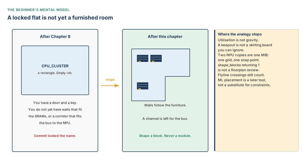
Sit with a flat you have just been handed the keys to. Chapter 8 locked the door. The directory downstairs now says CPU_CLUSTER, NPU_CORE, ISP, SOC_PERIPH. You can give the key to another engineer. You cannot yet put the beds in, because the rectangle you committed is a landlord’s sketch, not a furniture plan. The SRAMs are beds that do not fold. The channel is the corridor the fire code demands. Shaping cuts the rooms so the corridor exists. Placement sits the beds down. Keepout is the paint around each bed so nobody puts a desk on the mattress.
A module is still only a name on the directory. You do not shape a name. You shape a block — the locked flat. If you skip from “I committed” to “the SRAMs look tidy in the GUI”, you have skipped the corridor, the paint, and the report that counts crossings. The analogy stops being silicon in four places: utilisation is not gravity; a keepout is not a wall the other beds respect unless you asked for hard_macro; two identical NPU drawings are a multiply instantiated block (MIB), one grid, two cells; and a return value of 1 is not a fire-safety certificate.
The precise engineering model
The design database now holds physical hierarchy blocks. Each block has a boundary, an origin, site arrays, and — if you committed a module boundary that already sat in the core — member cells placed relative to that origin. Hard macros inside those blocks are still, until this chapter, unconstrained furniture. They have library-legal orientations. They do not yet have a keepout, a relative offset, or a placement style.
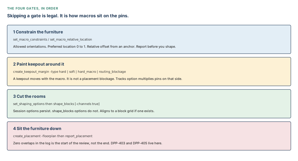
Sit with four gates, in order. First you constrain the macros: allowed orientations, a preferred location in the unit square, optional pin-to-track or grid alignment, optional relative location from an anchor. Second you paint keepouts that travel with the macro — not placement blockages, even though they behave like them. Third you shape the committed blocks: session options that persist, a shape_blocks call whose own options do not persist, channels, utilisation slack, optional constraint file or Tcl groups. Fourth you sit the furniture down with create_placement -floorplan, then you read a report that can print DPP-403 (cell overlaps a block) and DPP-405 (hard macro overlaps hard macro).
Skipping a gate is legal. It is how macros sit on the pins. It is how a channel of 2.091 mm² = 2,091,000 µm² on paper becomes a tangle of flylines in the report. The tool will not refuse. The next engineer will.
Do not confuse these
| This | Is not this | Why the mix-up is expensive |
|---|---|---|
| Module | Block | A module is logical. A block is physical, after commit. You shape a block. You never shape a module. |
set_shaping_options | Options on shape_blocks | The first persist for the session. The second die with the call. Yesterday’s -channels false is gone unless you type it again. |
Keepout type hard | Keepout type hard_macro | Hard stops standard cells. It does not stop other hard macros. The channel between SRAMs is hard_macro. |
| A return value of 1 | A clean shaping or placement report | shape_blocks returning 1 means the command finished. Flylines and DPP-403 live in the report. |
| Constraint file | Tcl shaping groups | The file is passed with -constraint_file. Tcl groups are ignored until plan.shaping.import_tcl_shaping_constraints is true (default false). |
Command heading create_shaping_constraint | Syntax line create_shaping_constraints | Follow the heading (singular). Confirm with man on your build. Do not invent a plural command from the Syntax line. |
boundary_channels (plural) | boundary_channel (singular) | The command type list is plural. Flow examples also wrote the singular. Use the plural in new Tcl. Confirm with man. |
on_edge / freeform / islands / hybrid | One remembered default | The application-option text is corrupted in one source. Read plan.macro.style back. Timing-driven floorplan placement only applies if the style is on_edge. |
| Defining a PG strategy | compile_pg | A block grid can be derived from a strategy you have defined. Compiling the mesh is Chapter 10. |
place_macro_ml | Constraints and keepouts | Machine learning is not a substitute for orientations, relative locations, or hard-macro keepouts. It honours them; it does not invent the ones you skipped. |
Concepts built from first principles
Part 1 — Constrain the macros before you cut the rooms
Before block shaping, you tell the tool how the furniture is allowed to sit. Collect the hard macros. Sit with the filter: is_hard_macro and not is_physical_only. Physical-only fillers are not the SRAMs you mean.
# Nimbus-8: every real hard macro, not physical-only fillers
icc2_shell> set macro_cells [get_cells -physical_context \
    -filter "is_hard_macro && !is_physical_only" -quiet]
icc2_shell> set_macro_constraints -allowed_orientations {R0 R180} $macro_cells
icc2_shell> report_macro_constraints
The report has two orientation columns. Allowed is what you just set. Legal is what the reference library already permitted. For hard macros, -allowed_orientations further restricts the library. For I/O cells it overrides the library. Sit with that fork before you copy a list from an SRAM onto a pad.
Other options, used when you mean them:
-preferred_location {x y}— each value from 0 to 1. (0, 0) is the lower-left of the block bounding box; (1, 1) is the upper-right. A teaching SRAM you want near the top ofu_cpu_clustermight be{0.5 0.9}.-align_pins_to_tracksor-alignment_grid— one, not both. Align signal pins to the tracks of their layer, or align the macro to a named placement grid.-alignment_point {x y}— a point in the master that must sit on-grid. Default is the origin. Ignored unless you also pass-alignment_grid.-alignment_orientation_set—all(default),R0meaning {R0, R180, MX, MY}, orR90meaning {R90, R270, MXR90, MYR90}. Requires the grid or pin-track option.-style on_edge | freeform | auto— only whenplan.macro.styleis hybrid. Here lives a conflict you must not silently pick.
The command Syntax for set_macro_constraints -style defaults to freeform. The flow text that describes the same option lists auto | on_edge | freeform and calls auto the default — the tool decides, from macro size and blocked routing layers, whether a macro goes on-edge or freeform. One Arguments note even spells the application option plan.macro.stype. The option you set is plan.macro.style.
Do not memorise either default. Set the value you mean. Then:
icc2_shell> report_macro_constraints -style
icc2_shell> report_app_options plan.macro.style
icc2_shell> man set_macro_constraints
Optional switches on report_macro_constraints limit the report to that constraint: -allowed_orientations, -preferred_location, -alignment_grid, -align_pins_to_tracks, -style. Default object list: all hard macros. Also reports legal orientations from the library.
Shaping cuts rooms around furniture that still has freedom. If an SRAM is allowed to rotate to R90 on a library that packed its pins for R0, the channel you sized for the east edge is now the wrong edge. Constraints are cheap. A reshaped block with the wrong orientations is an afternoon.
-style explicitly. The default conflict is real; the report is the tie-breaker.Relative location: a corner story
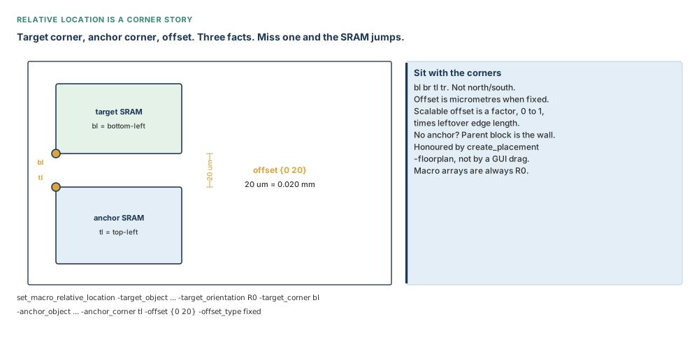
create_placement -floorplan honours set_macro_relative_location. You name a target, a target orientation, a target corner, an anchor corner, and an offset. If you omit -anchor_object, the anchor is the target’s current parent block. That is the usual “park this SRAM 20 µm inside the lower-left of the CPU cluster” case. Valid named corners are bl, br, tl, tr. Arguments also document numbered rectilinear corners 1, 2, 3, … clockwise from the lowest-left edge, not 0. Use the four names until you have a rectilinear outline and have confirmed the numbers with man.
Offset type defaults to fixed. Distances are micrometres. A scalable offset uses this formula:
target position = anchor position + offset × (scale_edge_length − used_length)
You may split the types: -offset_type {fixed scalable} for x fixed and y scalable. If you omit -scale_edge with a scalable offset, the tool uses the bounding-box width and height. Macro arrays always use orientation R0.
# two 200 um × 160 um SRAMs in u_cpu_cluster
# 20 um gap: target bottom-left sits 20 um above the anchor top-left
# 200 um = 0.200 mm; 160 um = 0.160 mm; area each 0.0320 mm² = 32,000 µm²
icc2_shell> set_macro_relative_location \
    -target_object [get_cells u_cpu_cluster/u_sram_1] \
    -target_orientation R0 -target_corner bl \
    -anchor_object [get_cells u_cpu_cluster/u_sram_0] \
    -anchor_corner tl \
    -offset {0 20} -offset_type fixed
icc2_shell> report_macro_relative_location
Sit with the three facts on that command: which corner of the parked SRAM, which corner of the SRAM already placed, and the offset in micrometres. Miss one and the second SRAM jumps by a whole width — 200 µm = 0.200 mm — into the channel you were about to protect.
bl, br, tl, tr. Offsets are micrometres. Teaching purpose: make the three facts visible before the reader types the command.You want the SRAM a fraction of the way along a growing channel rather than a fixed 20 µm? Pass -offset_type scalable and an offset factor such as {0.5 0.5}. The formula uses scale_edge_length − used_length. A fixed 20 µm does not grow when the block grows. A factor does. That is a choice, not a default you should leave unexamined.
Part 2 — Keepouts: paint that travels with the SRAM
A keepout is not a placement blockage. It behaves like one, and it moves when the hard macro moves. That is the point. You paint the SRAM once; the paint follows it through shaping and placement.
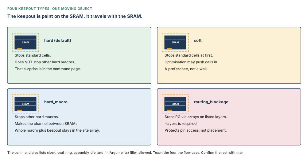
The flow describes four types. The command Syntax lists those four and then more. Teach the four. Confirm the rest with man create_keepout_margin — do not pretend they are not there.
| Type | What it prevents | What it does not |
|---|---|---|
| hard | Default. Standard cells in the margin. | Does not prevent other hard macros from sitting in the same paint. That sentence is on the command Arguments. The flow text that says “prevents standard cells” is true and incomplete. |
| soft | Standard cells, at first. | Optimisation may push cells in. A preference, not a wall. |
| hard_macro | Other hard macros and other hard-macro keepouts. Keeps the whole macro plus keepout inside the site array. | Does not, by itself, stop standard cells the way hard does. This is the channel between SRAMs. |
| routing_blockage | PG via arrays on the layers you list, so they do not block pin access. | Not a placement rule. -layers is required; an empty list is an error. |
The same command Syntax also lists clock, seal_ring, and assembly_die. Arguments add filler_allowed, which is not on the Syntax line. seal_ring and assembly_die are outer only, positive, on a block. Sit with man before you type them. This book will not invent their behaviour beyond that.
# four types the flow uses, on every Nimbus-8 hard macro
icc2_shell> set all_hm [get_cells -hierarchical -filter "is_hard_macro==true"]
icc2_shell> create_keepout_margin -type hard -outer {2 2 2 2} $all_hm
icc2_shell> create_keepout_margin -type hard_macro -outer {5 5 5 5} $all_hm
icc2_shell> create_keepout_margin -type routing_blockage -layers {M2 M3 M4} \
    -outer {1 1 1 1} $all_hm
icc2_shell> create_keepout_margin -type soft -outer {8 8 8 8} $all_hm
-outer and -inner take {left bottom right top} in micrometres, all four required, all ≥ 0. Inner keepouts apply to physical designs, not leaf cells. Outer apply to leaf cells and physical designs. You may also size from tracks instead of a fixed margin; that option is mutually exclusive with -inner and -outer.
man. Teaching purpose: stop the reader treating keepout as one kind of wall.Tracks arithmetic
With -tracks_per_macro_pin, the tool multiplies the number of tracks you specify by the number of pins on that side of the macro, then by the track pitch of the layer those pins use. Sit with a teaching SRAM that has 40 pins on the east edge, a request of 0.5 tracks per pin, and this book’s M2 pitch of 0.048 µm:
0.5 × 40 × 0.048 µm = 0.960 µm
That is not a millimetre. It is just under a micron of paint on that side — about 1.7 row heights would be 0.576 µm × 1.7, which is a different number, so do not mix the stories. Optional -min_padding_per_macro (default: minimum grid size, 0) and -max_padding_per_macro (no maximum by default) clamp the result. They are valid only with the tracks option.
# 0.5 tracks per pin × 40 east pins × 0.048 µm M2 pitch = 0.960 µm
icc2_shell> create_keepout_margin -type hard_macro \
    -tracks_per_macro_pin 0.5 $all_hm
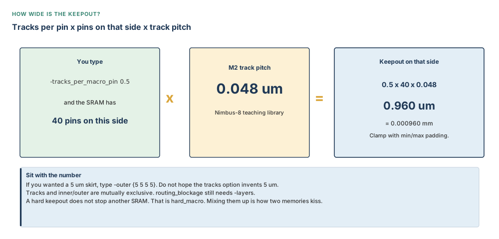
You set -type hard, looked at a tidy halo, and assumed no SRAM could sit in that halo. Another hard macro may. The command Arguments say so. If the channel between two 200 µm × 160 µm SRAMs (each 0.0320 mm² = 32,000 µm²) must stay empty of furniture, that is hard_macro, not hard.
Part 3 — Space between connected blocks, arrays, and the edit group you can throw away
Macros parked on a block edge steal the routes that should have crossed that edge. The application option that reserves the edge for later pins is plan.macro.cross_block_connectivity_planning, set on the block. Values recovered from the option text:
hard— analyse connectivity between child blocks; keep macros off a section of the shared boundary so the free edge can take pins later.soft— the same idea, allowed to yield.unset— inherit from the parent. This is the labelled default.false— turn the planning off.
# reserve the CPU–NPU facing edge for pins, not for SRAMs
icc2_shell> set_app_options -block CPU_CLUSTER \
    -name plan.macro.cross_block_connectivity_planning -value hard
Move bounds and voltage areas use the same four values on the attribute interface_connectivity_planning:
icc2_shell> set_attribute -name interface_connectivity_planning \
    -value hard [get_voltage_areas VA1]
There is no dedicated command named interface_connectivity_planning. It is an attribute. Confirm with man set_attribute and by reading the attribute back.
Macro arrays
Two or more macros can sit as one unit: shared orientation, shared channel, optional flipping, a fill pattern. create_macro_array requires -num_rows and -num_cols. Channel lists default to 0 (keepouts are not included in that 0). Alignment default center. Fill pattern default by_row. -create_group defaults to true; the default name is MACRO_ARRAY_#. Orientations, if you pass them, use the compass set N, FN, S, FS, E, FE, W, FW (the same eight as R0, MY, R180, MX, R270, MYR90, R90, MXR90). Default: leave orientations unchanged.
# four SRAMs as a 2×2 array inside the CPU cluster
icc2_shell> create_macro_array -num_rows 2 -num_cols 2 \
    -name cpu_sram_quad \
    [get_cells u_cpu_cluster/u_sram_*]
The array is an edit group. Removing the grouping does not delete the macros:
icc2_shell> remove_edit_groups {cpu_sram_quad}
remove_edit_groups returns the count removed. Contained objects stay in the design. -force ignores locked status. Sit with that: you threw away the seating plan, not the chairs.
hard or soft connectivity planning. Group SRAMs with an array when they must travel as one; remove_edit_groups undoes the group, not the cells.Part 4 — Cut the rooms: persistent options, a non-persistent command, a count of crossings
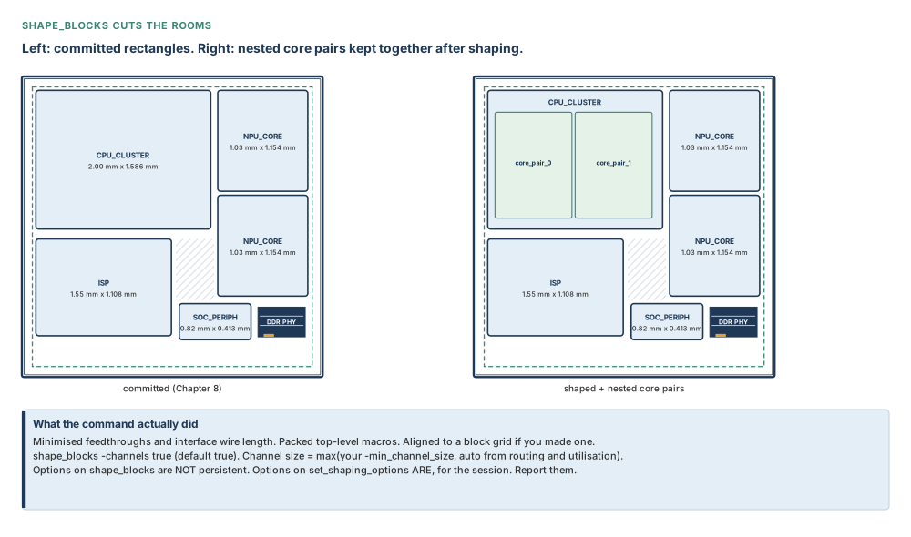
After commit, the rectangles are real designs. They are not yet the right rectangles. Shaping refines each block boundary from the rough shape Chapter 8 committed, considering utilisation, channel width, keepouts, feedthroughs and interface wire length. If a block grid exists, shapes align to it. If a placement abstract exists, shaping can use it to go faster. Missing abstracts are created if needed. If an object has no utilisation of its own, the design utilisation is used — on Nimbus-8 that is 0.617.
Two commands, two lifetimes. Sit with that before you type either.
set_shaping_options persists for the session. Defaults you must not invent: -min_channel_size 0 (micrometres; only consulted when shape_blocks -channels is in force), -guard_band_size 0 (new voltage areas only; existing guard bands unchanged), -utilization_slack 0.1 (ten per cent), -keep_top_level_together true, -add_channel_blockages soft (used by incremental congestion-driven shaping). -reset restores every default. Returns 1 or 0.
shape_blocks options do not persist. -channels defaults to true; channel size is the maximum of your -min_channel_size and an automatic size from routing resources and utilisation. -constraint_file is mutually exclusive with -incremental. Incremental strategies are congestion_driven (needs prior global routing; MIB instances are not moved) and target_utilization_driven (does not support -channels false). Default is neither strategy. -pg_strategy needs a strategy defined with set_pg_strategy … -core if you want whole-design meshes considered — still not compile_pg. Returns 1 or 0.
# session options persist; shape_blocks options do not
icc2_shell> set_shaping_options -keep_top_level_together true \
    -min_channel_size 40 -utilization_slack 0.1
icc2_shell> report_shaping_options
icc2_shell> shape_blocks -channels true
Forty micrometres is 0.040 mm. It is a floor, not the channel area. Nimbus-8’s leftover channel area is still 2.091 mm² = 2,091,000 µm² if the block-boundary total remains 8.149 mm² = 8,149,000 µm² inside a 10.24 mm² = 10,240,000 µm² core. Shaping may change the outlines; it must not spend that corridor without you noticing.
Flylines are a product, not a feeling
report_block_shaping is the review. Useful switches include -core_area_violations, -overlaps, -flyline_crossing, -chimney_area, -unaligned_pins_estimate, -orientation_violations (uses allowable_orientation), -hierarchical, -verbose minimum | low | high (default low). -detour_estimate needs the top-level cells placed first. Default cells: all blocks. Default hierarchy: current block only.
Sit with the flyline rule. If 100 flylines run from A to D and 2 flylines from C to B cross them, the report is 2 × 100 = 200 crossings for that pair. If the A–D bundle is gone and only C–B remains, the report is no cross flylines for that pair. Neighbours whose flylines do not cross anyone else contribute nothing. Smaller is better. The number is a product of two counts, not a vibe from the GUI.
icc2_shell> report_block_shaping -core_area_violations -overlaps \
    -flyline_crossing
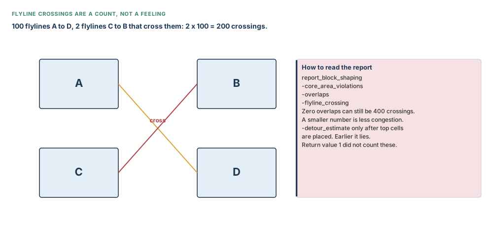
shape_blocks returns 1 when it finishes. That is not zero overlaps, not zero core-area violations, and not a flyline product you would defend. Read report_block_shaping. Then look at the outlines. Then, and only then, call the rooms cut.
set_editability can allow or prevent shaping on blocks. Returns a count of blocks whose hierarchical edit control changed. -value defaults to true. Without -blocks, the current block is the target. A later placement section will use -from_level 1 -value false to keep lower levels still.
shape_blocks die with the call. A return of 1 is a heartbeat, not a review.Part 5 — Constraint files and Tcl groups: two seating plans, one switch
You can tell shaping where to sit the rooms in a text file, or in Tcl. They are not the same switch.
Pass a file with shape_blocks -constraint_file (mutually exclusive with -incremental). Keywords the command documents: allowed_orientation, aspect_ratio, utilization, boundary; boundary_channel_size, channel_size, guard_band; define_group; arrange_in_box, arrange_in_array. Global-scope allowed: boundary_channel_size, channel_size, guard_band, utilization. Array directions: north, west, south, east. A rigid outline is type: rigid plus shape:. Coordinates in the file are micrometres. Block constraints are not nested inside other block constraints.
# teaching file nimbus8_shape.con — numbers are micrometres
# CPU 2000 um × 1586 um = 2.00 mm × 1.586 mm = 3.172 mm² = 3,172,000 µm²
# (file contents, not a shell command)
utilization { target: 0.617; }
channel_size { size=40; }
block NIMBUS8 {
    define_group CPU_AND_NPU {
        arrange_in_array {
            contents: block_inst u_cpu_cluster, block_inst u_npu_core_0;
            direction: east;
        }
    }
    utilization {
        block_inst u_isp;
        target: 0.617;
    }
}
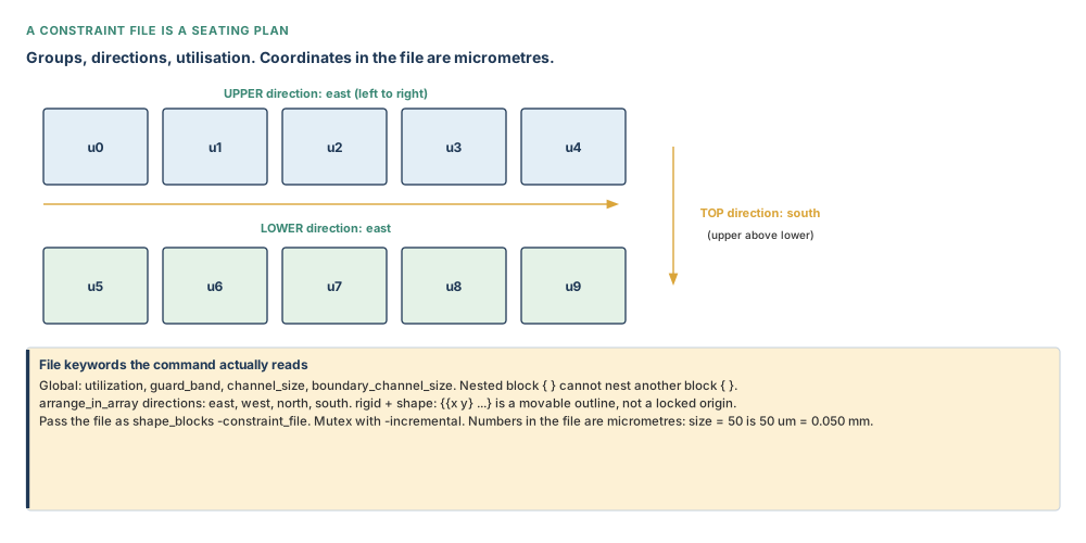
shape_blocks -constraint_file. Teaching purpose: show the file as a plan the command will read, not as decoration.Tcl groups: the same seating plan, typed — and ignored by default
plan.shaping.import_tcl_shaping_constraints is Boolean, default false. Until you set it true, create_group -shaping and create_shaping_constraint are furniture in a warehouse shape_blocks will not visit. Optional plan.shaping.report_import_constraints is an enum, default off; values log, file (writes shape_blocks_imported_constraints.txt, unique suffix if the name exists), both.
icc2_shell> set_app_options -name plan.shaping.import_tcl_shaping_constraints \
    -value true
icc2_shell> set_app_options -name plan.shaping.report_import_constraints \
    -value both
icc2_shell> create_group -name TOP_ROW -shaping \
    [get_cells {u_cpu_cluster u_npu_core_0 u_npu_core_1}]
icc2_shell> create_group -name BOTTOM_ROW -shaping \
    [get_cells {u_isp u_soc_periph}]
icc2_shell> create_group -name TOP_AND_BOTTOM -shaping \
    [get_groups -shaping {TOP_ROW BOTTOM_ROW}]
Shaping groups must be sets. Members: voltage areas, move bounds, cells, other shaping groups. create_group -type defaults to set (collection allows duplicate members). -remove_when defaults to no_auto_removal. Arguments document -repelling, mutually exclusive with -shaping; the Syntax line does not list -repelling. Confirm with man create_group before you type it. You can reorder members with set_shaping_group_order — confirm that command with man on your build.
Then the heading you type is create_shaping_constraint (singular). The Syntax line prints create_shaping_constraints (plural). Follow the heading. Confirm with man. One constraint per type per object; a second of the same type replaces the first. Objects: voltage area, move bound, cell, shaping group, or block.
# heading is singular; Syntax line prints a plural — follow the heading
icc2_shell> create_shaping_constraint [get_groups -shaping TOP_ROW] \
    -type array_layout -array_layout east
icc2_shell> create_shaping_constraint [get_groups -shaping BOTTOM_ROW] \
    -type array_layout -array_layout east
icc2_shell> create_shaping_constraint [get_groups -shaping TOP_AND_BOTTOM] \
    -type array_layout -array_layout south
icc2_shell> shape_blocks
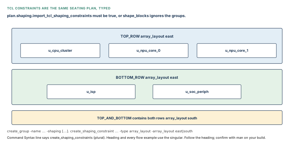
man. Teaching purpose: show the group hierarchy and the switch that makes shape_blocks notice it.Valid -type values include external_channels, child_default_channels, boundary_channels, target_location, reference_region, alignment_point, parent_object, aspect_ratio, boundary_area, child_default_utilization, utilization, array_layout, allowable_orientation, is_rigid_boundary. Sit with one more spelling conflict: the command type list uses boundary_channels (plural). Flow examples also wrote boundary_channel (singular), and at least one example used each. In new Tcl, use the plural from the type list. Confirm with man create_shaping_constraint.
Create the channel, then assign it
create_shaping_channel always creates a new channel object. At least one spacing option is required: -left_min, -left_max, -bottom_min, -bottom_max, -right_min, -right_max, -top_min, -top_max, optional -neighbor. Then you assign that object with create_shaping_constraint. Creating is not assigning.
# 40 um = 0.040 mm floor around the core contents
icc2_shell> set ch40 [create_shaping_channel \
    -left_min 40 -right_min 40 -top_min 40 -bottom_min 40]
icc2_shell> create_shaping_constraint [current_block] \
    -type boundary_channels -object_channel $ch40
Three assignment types to keep straight: boundary_channels for the top-level design; external_channels along the sides of an object (not on the current top-level block); child_default_channels as the default external channel for nested children. Report with report_shaping_channels and report_shaping_constraints. Remove with remove_shaping_channels and remove_shaping_constraints. A boundary_status constraint is derived and cannot be removed. Removing a channel that is still assigned may unset or remove that constraint.
You build a beautiful group hierarchy and forget the import option? shape_blocks runs, returns 1, and ignores every group. Default false is not a bug. Turn it on, set the report-import option so you can see what was read, and shape again.
boundary_channels in new Tcl; confirm with man.Part 6 — A grid for a multiply instantiated block, without compiling the mesh
A multiply instantiated block (MIB) is one reference, more than one cell. Nimbus-8’s two NPU instances share the NPU_CORE drawing: each instance is 1.03 mm × 1.154 mm = 1.189 mm² = 1,189,000 µm². During shaping, the tool aligns MIB instances to a block grid if one exists. One reference associates with one grid; one grid may associate with many references.
You may derive the grid from a power-plan strategy plus site rows (or site arrays), or you may type the steps yourself. Defining the strategy is required for the derived form. Instantiating the mesh with compile_pg is not. That compile is Chapter 10. Sit with that: you are borrowing the pitch, not building the straps.
# define a strategy so a grid can be derived — do not compile_pg here
icc2_shell> create_pg_mesh_pattern pat_mesh -layers { \
    {{vertical_layer: M4} {width: 3} {spacing: 3} {pitch: 20} {offset: 2}} \
    {{horizontal_layer: M5} {width: 3} {spacing: 3} {pitch: 20} {offset: 2}}}
icc2_shell> set_pg_strategy s_mesh -core \
    -pattern {{name: pat_mesh} {nets: VDD VSS}}
icc2_shell> create_grid npu_grid -type block \
    -site_rows [get_site_rows] -pg_strategy s_mesh
icc2_shell> report_grids
create_grid -type defaults to block (user is also valid). Manual form: -x_step / -y_step default to the litho grid pitch; offsets default to 0. Allowed orientations on a manual block grid default to R0, MX, MY, R180. Auto-derived options and manual step options are mutually exclusive. If the floorplan has site arrays rather than site rows, pass -site_arrays instead.
# or type the pitch: 20 um = 0.020 mm
icc2_shell> create_grid -type block npu_grid2 -x_step 20.0 -y_step 20.0 \
    -x_offset 0 -y_offset 0
icc2_shell> set_block_grid_references -designs {NPU_CORE} -grid npu_grid2
Snap point: default is the origin of the block. A user-specified snap point is FIXED. shape_blocks will not move a fixed snap point. -reset on set_block_grid_references drops the association, moves the snap point back to the origin, and unfixes it.
# 100 um = 0.100 mm into the NPU drawing
icc2_shell> set_block_grid_references -designs NPU_CORE -grid npu_grid2 \
    -snap_point {100.0 100.0}
icc2_shell> get_attribute [get_cells u_npu_core_0] snap_point
icc2_shell> get_attribute [get_cells u_npu_core_0] block_grid
icc2_shell> snap_cells_to_block_grid -designs NPU_CORE
snap_cells_to_block_grid needs at least one of -designs, -grid, or -cells. -designs is mutually exclusive with the other two. -grid plus -cells snaps those cells’ origin to that grid and may ignore the association. Off-grid associated instances show as errors in report_grids.
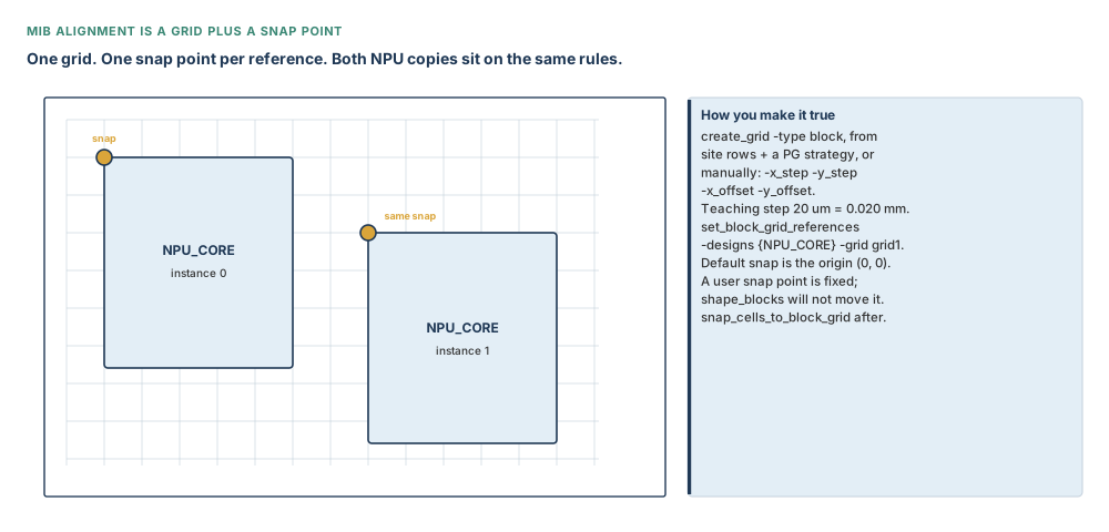
Flip one NPU instance and the pins must still meet the parent’s tracks. A shared grid and a fixed snap point are how two copies of one drawing stay push-downable. Without them, Chapter 8’s congruence check at commit is undone by a later rotation.
Part 7 — Sit the furniture down
After the rooms are cut, create_placement -floorplan decides which macro sits where, and places standard cells as well unless you asked it not to. Skip a macro by fixing it (set_fixed_objects or the physical_status attribute). plan.macro.macro_place_only true (default false, global-only) stops the command as soon as macro locations are decided, without standard-cell placement.
# optional: macros only, then the full floorplan placement
icc2_shell> set_app_options -name plan.macro.macro_place_only -value false
icc2_shell> report_app_options plan.place*
icc2_shell> set_editability -from_level 1 -value false
icc2_shell> create_placement -floorplan
Effort: Syntax lists very_low | low | medium | high, default high, except on-edge and island floorplan placement default medium. Flow step text omits very_low. Do not invent a fifth word; confirm with man create_placement. -congestion_effort defaults to medium and is only valid with -congestion. -incremental also enables -use_seed_locs. -from is only with -floorplan -incremental and style freeform or hybrid; default entry macro_legalization; channel_sizing only if -congestion is also on. Values of -from: combined_placement (most movement), macro_legalization, channel_sizing (least).
The report that can embarrass you
report_placement is where DPP-403 and DPP-405 live. DPP-403: a cell overlaps a block (physical-hierarchy violation). DPP-405: two hard macros overlap. Defaults worth knowing: physical-hierarchy violations all; voltage-area internal; wirelength all; verbose low; pin-track violations none. Single-row-height standard-cell physical-hierarchy violations are not reported. Optional -verbose high writes the list you actually debug from.
icc2_shell> report_placement -physical_hierarchy_violations all \
    -wirelength all -hard_macro_overlap
reset_placement unplaces cells in the core. It does not unplace fixed and dont_touch cells. -spread_cells spreads cells to the right of the block.
identify_channels photographs gaps that already exist. It does not create them. Default output file channels.txt. Horizontal threshold: channels taller than the value are not reported. Vertical: channels wider than the value are not reported. Output lines look like direction (xlo ylo) (xhi yhi), with horizontal, vertical, or crossed_area. The Syntax line prints a stray J after -vertical_threshold. Do not type it. Confirm with man identify_channels.
icc2_shell> identify_channels -output_filename nimbus8_channels.txt \
    [get_cells u_cpu_cluster/u_sram_*]
Styles: read the option back
plan.macro.style is an enum honoured by create_placement -floorplan. Flow text describes four values. One application-option source has a corrupted default glyph; ASCII later on the same page still names the option. Flow text independently says the default is on_edge. Do not memorise the glyph. Read it back.
icc2_shell> report_app_options plan.macro.style
icc2_shell> set_app_options -name plan.macro.style -value on_edge
on_edge— macros along the edges of blocks, voltage areas, and move bounds. The style for which timing-driven floorplan placement applies (Part 9).islands— some macros float away from partition edges in tightly packed groups. Only a small percentage of the design area can be islands.freeform— macros sit individually among standard cells. Congestion-driven channel sizing, partial blockages in channels, PG resources in the congestion picture, automatic pin-protection blockages.hybrid— large macros (or macros that block many routing layers) tend to go on-edge; smaller ones freeform. Any number may float. Unlike islands, the floaters are not packed as a group. Under hybrid,set_macro_constraints -styleper macro is live — and that is the option whose default conflict you already met.
Island style: a bound, then an attribute
If the style is islands, some macros float away from partition edges in tightly packed groups. Only a small percentage of the design area can be islands. You may optionally name which macros travel together by creating a bound, then telling that bound it is allowed off the edge.
# optional island: three CPU SRAMs packed off the wall
icc2_shell> set_app_options -list {plan.macro.style islands}
icc2_shell> create_bound -effort high -name cpu_island \
    [get_cells {u_cpu_cluster/u_sram_0 \
                u_cpu_cluster/u_sram_1 \
                u_cpu_cluster/u_sram_2}]
icc2_shell> set_attribute -objects [get_bounds cpu_island] \
    -name is_off_edge -value true
icc2_shell> create_placement -floorplan
create_bound -type defaults to soft. -effort is valid with a named collection like this; it is not valid with -type hard. The attribute is_off_edge is what turns “a bound around three SRAMs” into “these three may sit off the wall as an island”. Confirm the attribute on your build with man set_attribute and by reading it back. Without the bound, island style still floats a small packed percentage; the bound is how you point at these three.
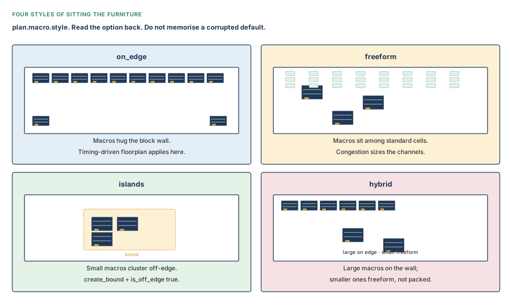
on_edge. Read the option back. Teaching purpose: put four pictures on the page so the four words are not synonyms.Integrated freeform (iFFMP), briefly
plan.macro.integrated recovered ASCII tokens: false (default), true, two_pass. When true, freeform macro placement is integrated with the later place_opt flow. This chapter sits macros with create_placement -floorplan. The integrated flow is a later-implementation choice, not a substitute for the constraints you set here. If place.coarse.fix_hard_macros is true, place_opt does not place hard macros regardless of this option. Confirm current tokens with report_app_options plan.macro.integrated.
A blockage that only macros listen to
Only type hard_macro on create_placement_blockage is honoured by hard-macro placement. Default type is hard (standard cells). Boundary form on the command is a pair of points:
# 50 um = 0.050 mm; 400 um = 0.400 mm — teaching rectangle, not a Nimbus-8 block
icc2_shell> create_placement_blockage -type hard_macro \
    -boundary {{50 50} {400 400}}
A different document shows a flat four-number list {10 20 100 200}. Use the pair-of-points form. Confirm with man create_placement_blockage. On a hard-macro blockage, attribute is_pin_protect defaults to false: macros may abut the edge. True reserves space around the blockage for pin placement. Default purpose is user (not auto-removed).
-floorplan, then read DPP-403 and DPP-405. Styles are four pictures; read the option back. Identify channels photographs gaps; it does not create them.Part 8 — Machine-learning macro placement, as working knowledge
The tool can explore many floorplans, train on congestion and total-negative-slack data, and pick a ranking. That is not a substitute for the constraints in Parts 1–3. The flow honours keepouts and constraints; it does not invent the ones you skipped. Hierarchical designs: ML placement supports only on_edge. Soft blocks with abstract or design views are listed as unsupported. After ML placement, PG is removed even if you passed a PG script — re-create the mesh later (Chapter 10).
place_macro_ml requires -host_options. -mode default both; allowed tokens include congestion, tns, both, power, wirelength, wns, thermal, all (and a list). all means congestion, TNS, and power. -effort default medium; hierarchical designs medium only. -style default on_edge; hierarchical on_edge only; auto explores hybrid and freeform. Work directory default ./mlmp_dir. -exploration_file is freeform only. -floorplan_file is on_edge and hybrid only. The command removes PG, user and global routes, placement blockages (keep via plan.macro.ml_keep_existing_placement_blockages), routing blockages (keep via the routing twin), and unlocked switch, cap and well-tap cells.
icc2_shell> place_macro_ml -host_options mlmp -mode both -style on_edge
create_mlmp_data -output is required; the suffix must be csv. A hidden .signature file is also written. Both files are needed.
icc2_shell> create_mlmp_data -output hm.csv
select_mlmp_result: Syntax option is -result_file. The printed example uses -result_file_name. Use the Syntax name. Confirm with man select_mlmp_result. -mode default both.
# Syntax: -result_file. Example prints -result_file_name — follow Syntax
icc2_shell> select_mlmp_result -mode both -result_file mlmp_result_file
explore_macro_placement also requires -host_options. Style default on_edge; mode default both. Writes a DSO setting file named mlmp_compile_permutons.tcl and five floorplans from the ranking. One printed example misspells -on_edge_ratio as -on_edge_ration. Type the real option. Confirm with man.
The Macro Placement Assistant, briefly
If you are placing macros by hand and the channels between them are becoming alleys, the GUI has an assistant for grouping macros and trying placements. Open it from View → Assistants → Macro Placement Assistant, or from the toolbar button of the same name. Click Initialize before you do anything else. It is a refinement tool for a furniture plan you already constrained, not a substitute for Parts 1–3, and not a substitute for report_placement. This book stays in the shell for the rest of the chapter; the assistant is named so you can find it, not so you can skip the reports.
Spacing as a pair of distances
plan.macro.spacing_rule_heights and plan.macro.spacing_rule_widths are each a pair: first value exact, second at least. Default 0m 0m (examples write {0um 0um}) means no rule. Honoured by create_placement -floorplan. Teaching pair:
# exactly 2 um, or at least 10 um, vertically and horizontally
icc2_shell> set_app_options -list {plan.macro.spacing_rule_heights {2um 10um}}
icc2_shell> set_app_options -list {plan.macro.spacing_rule_widths {2um 10um}}
{0um 10um} means abutted or at least 10 µm. {10um 10um} means at least 10 µm. These rules do not replace a hard_macro keepout. They are a neighbour-distance contract the placer honours when it can see it.
-result_file from Syntax. Spacing pairs are exact-or-at-least, in micrometres.Part 9 — Congestion-driven and timing-driven floorplan placement
Two application options, same three value words, different defaults, one important gate.
plan.place.congestion_driven_mode is an enum. Recovered values: macro, std_cell, both. Labelled default macro. Used with create_placement -floorplan -congestion. Must be set on a block. -as_user_default is mentioned for applying to all blocks. ASCII example: set_app_options -list {plan.place.congestion_driven_mode both}.
plan.place.timing_driven_mode is an enum. Recovered values: std_cell, macro, both. Labelled default std_cell. Controls create_placement -floorplan -timing_driven. The ASCII that survived says this option only applies if plan.macro.style is on_edge. If you set both and then place freeform, you have typed a wish the style will not honour. Read both options back.
icc2_shell> report_app_options plan.place.congestion_driven_mode
icc2_shell> report_app_options plan.place.timing_driven_mode
icc2_shell> report_app_options plan.macro.style
icc2_shell> set_app_options -list {plan.place.congestion_driven_mode both}
icc2_shell> set_app_options -list {plan.place.timing_driven_mode both}
icc2_shell> create_placement -floorplan -congestion -timing_driven
Buffering-aware timing is a different switch on the command: create_placement -floorplan -congestion -buffering_aware_timing_driven. It estimates later buffering of long and high-fanout nets. Confirm current combination rules with man create_placement.
You set plan.place.timing_driven_mode to both, ran -timing_driven, and the style was freeform or hybrid. The option text says timing-driven mode applies when the style is on_edge. Read the three options back before you claim a timing-aware furniture plan.
macro, std_cell, both. Timing-driven floorplan placement is gated on on_edge. Read the options back.Inputs, outputs, and readiness
| Stage | Needs | Writes |
|---|---|---|
| Macro constraints | Committed blocks; hard macros with is_hard_macro && !is_physical_only | Allowed orientations, preferred locations, optional style under hybrid. Reportable. |
| Relative location | A movable (not fixed) target macro or array; an anchor, or the parent if omitted | A constraint create_placement -floorplan will honour. |
| Keepouts | A cell or physical design; layers if type is routing_blockage | Paint that travels with the object. Not a blockage object. |
| Connectivity planning | A block, move bound, or voltage area | An edge reserved (hard/soft) or inherited (unset) or off (false). |
| Shaping options | A session | Persistent min channel, slack 0.1, keep-top-together true, until you reset. |
| Shape | Committed blocks; optional abstracts, grid, constraint file or imported Tcl | New outlines aligned to a grid if one exists. Return 1. QoR lives in the report. |
| Tcl / file constraints | Import true for Tcl (default false); file path for -constraint_file | Groups, channels, utilisations shaping will read — if the switch matches the method. |
| Block grid | A defined PG strategy for the derived form, or manual steps; MIB references | A grid; a snap point (origin, or user-fixed); associated references. |
| Floorplan placement | Shaped blocks; style read back; macros unfixed unless you mean to skip them | Macro (and usually standard-cell) locations. DPP-403 / DPP-405 in the report. |
| ML placement | Host options; constraints you still intend to honour | A ranked furniture plan. PG removed. Not a replacement for Parts 1–3. |
Preflight checklist
- Every object you will shape is a block, sitting in the core, cells placed. No leftover module names pretending to be rooms.
- Hard-macro collection uses
is_hard_macro && !is_physical_only. Count matches the Hierarchy Browser from Chapter 8 (Nimbus-8: 72 SRAMs plus the DDR PHY). report_macro_constraintsshows the orientations you meant, including-styleif hybrid is on.- Relative-location report: corners and micrometre offsets you meant; omitted anchors really are the parent.
- Keepouts:
hard_macrowhere SRAM-to-SRAM channels must stay empty of furniture;hardnot used as if it fenced macros;-layerspresent on every routing-blockage keepout. report_shaping_optionsbeforeshape_blocks.-channelstyped this call if you need it (it does not persist).- If you used Tcl groups:
plan.shaping.import_tcl_shaping_constraintsis true. If you used a file:-constraint_file, not the Tcl switch. - MIB references associated with a block grid; snap points read back; PG strategy defined if the grid was derived; mesh not compiled as a substitute for that definition.
plan.macro.styleread back. If you will pass-timing_driven, the style ison_edge.- After placement:
report_placementwith overlaps and physical-hierarchy violations, not only the command’s return.
A shape_blocks that returned 1 with a flyline product you never read. A create_placement -floorplan whose GUI looks tidy because you never opened DPP-403. Tcl groups ignored because import defaulted to false. A hard keepout you treated as a fence between SRAMs. Timing-driven words on a freeform style. An ML run you treated as permission to skip orientations. None of these are crashes. All of them are the wrong floorplan.
Guided tool workflow
Numbered path from Nimbus-8’s committed blocks to shaped rooms with macros placed, on the same die you already know. Core a square 3.20 mm on each side = 10.24 mm² = 10,240,000 µm², utilisation 0.617. Channel target 2.091 mm² = 2,091,000 µm². Block-boundary total 8.149 mm² = 8,149,000 µm².
- Collect macros.
set_macro_constraints -allowed_orientations {R0 R180}on the SRAMs.report_macro_constraints. - Relative location for SRAM stacks inside
u_cpu_cluster(2.00 mm × 1.586 mm = 3.172 mm² = 3,172,000 µm²): targetbl, anchortl, offset{0 20}micrometres. Report. - Keepouts:
hardouter 2 µm for standard cells;hard_macroouter 5 µm between SRAMs; routing-blockage on M2–M4 with layers named. Optional tracks: 0.5 × pins × 0.048 µm. - Connectivity:
plan.macro.cross_block_connectivity_planninghard onCPU_CLUSTERandNPU_COREso facing edges stay pin-capable. - If a 2×2 SRAM quad must travel as one,
create_macro_array. Otherwise skip. set_shaping_options -min_channel_size 40 -utilization_slack 0.1 -keep_top_level_together true.report_shaping_options.- Optional seating plan: constraint file, or Tcl groups with import true and
boundary_channelsassigned from a channel you created.shape_blocks -channels true. report_block_shaping -core_area_violations -overlaps -flyline_crossing. Do not stop at return 1.- NPU MIB:
create_grid -type blockat 20 µm,set_block_grid_referencesonNPU_CORE, snap point read back,snap_cells_to_block_grid. PG strategy defined if derived; nocompile_pg. - Read
plan.macro.style.create_placement -floorplan.report_placementfor DPP-403 and DPP-405.identify_channelson the SRAM collection to photograph gaps.
Eight-point treatment of the commands that matter
For every important command: purpose, syntax, prerequisites, a small example, expected result, verification, common mistakes, and how to discover more. Additional options: man <command> and help <command>, as in Chapter 2. Do not invent flags from memory. Where two sources disagree, both are named below; set the value you mean and report it back.
| Command | The eight points |
|---|---|
| set_macro_constraints |
|
| set_macro_relative_location |
|
| create_keepout_margin |
|
| set_shaping_options / shape_blocks |
|
| create_group / create_shaping_constraint |
|
| create_grid / set_block_grid_references |
|
| create_placement |
|
| report_block_shaping / report_placement |
|
One continuous worked example — Nimbus-8
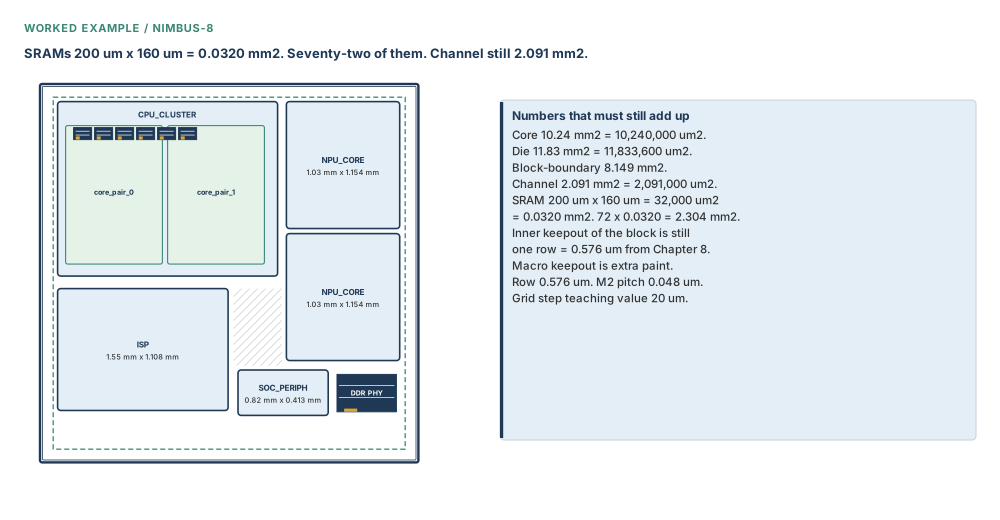
Situation. Chapter 8’s blocks exist in nimbus8.dlib. Top NIMBUS8. Four committed rooms, two NPU cells sharing one MIB reference NPU_CORE, nested core pairs still children of u_cpu_cluster. Seventy-two SRAMs, each 200 µm × 160 µm = 0.0320 mm² = 32,000 µm², total 2.304 mm² = 2,304,000 µm², plus the DDR PHY at 0.544 mm² = 544,000 µm², still sit where commit left them. You must constrain them, paint them, cut the rooms, and sit the furniture down without spending the channel.
Initial conditions. Core a square 3.20 mm on each side = 10.24 mm² = 10,240,000 µm², utilisation 0.617. Die a square 3.44 mm on each side = 11.83 mm² = 11,833,600 µm². Block-boundary total 8.149 mm² = 8,149,000 µm²; channel 2.091 mm² = 2,091,000 µm² (20.4 per cent of the core). Row height 0.576 µm. M2 pitch 0.048 µm. CPU 2.00 mm × 1.586 mm = 3.172 mm² = 3,172,000 µm² (2,000 µm × 1,586 µm). Each NPU 1.03 mm × 1.154 mm = 1.189 mm² = 1,189,000 µm² (1,030 µm × 1,154 µm). ISP 1.55 mm × 1.108 mm = 1.717 mm² = 1,717,000 µm² (1,550 µm × 1,108 µm). SoC periphery 0.82 mm × 0.413 mm = 0.339 mm² = 339,000 µm² (820 µm × 413 µm).
# 1. constrain — R0/R180 only on real hard macros
icc2_shell> set macro_cells [get_cells -physical_context \
    -filter "is_hard_macro && !is_physical_only" -quiet]
icc2_shell> set_macro_constraints -allowed_orientations {R0 R180} $macro_cells
icc2_shell> report_macro_constraints -allowed_orientations
# 2. stack two CPU SRAMs: 20 um gap, corners bl on tl
# 200 um × 160 um = 0.0320 mm² = 32,000 µm² each
icc2_shell> set_macro_relative_location \
    -target_object [get_cells u_cpu_cluster/u_sram_1] \
    -target_orientation R0 -target_corner bl \
    -anchor_object [get_cells u_cpu_cluster/u_sram_0] \
    -anchor_corner tl -offset {0 20} -offset_type fixed
icc2_shell> report_macro_relative_location
Expected: allowed column R0,R180; legal column still whatever the library permits. Relative report shows offset Y = 20.0000 µm, corners bl against tl. If the target was fixed, the command would have refused — unfix first with set_fixed_objects -unfix.
# 3. paint — hard does not fence SRAMs; hard_macro does
# 5 um = 0.005 mm outer; tracks check: 0.5 × 40 × 0.048 = 0.960 µm
icc2_shell> set all_hm [get_cells -hierarchical -filter "is_hard_macro==true"]
icc2_shell> create_keepout_margin -type hard -outer {2 2 2 2} $all_hm
icc2_shell> create_keepout_margin -type hard_macro -outer {5 5 5 5} $all_hm
icc2_shell> create_keepout_margin -type routing_blockage -layers {M2 M3 M4} \
    -outer {1 1 1 1} $all_hm
# 4. facing edges of CPU and NPU stay pin-capable
icc2_shell> set_app_options -block CPU_CLUSTER \
    -name plan.macro.cross_block_connectivity_planning -value hard
icc2_shell> set_app_options -block NPU_CORE \
    -name plan.macro.cross_block_connectivity_planning -value hard
# 5. session shaping options, then cut the rooms
# 40 um = 0.040 mm floor; slack 0.1; channels true this call
icc2_shell> set_shaping_options -min_channel_size 40 \
    -utilization_slack 0.1 -keep_top_level_together true
icc2_shell> report_shaping_options
icc2_shell> set_app_options -name plan.shaping.import_tcl_shaping_constraints \
    -value true
icc2_shell> set ch40 [create_shaping_channel \
    -left_min 40 -right_min 40 -top_min 40 -bottom_min 40]
icc2_shell> create_shaping_constraint [current_block] \
    -type boundary_channels -object_channel $ch40
icc2_shell> shape_blocks -channels true
icc2_shell> report_block_shaping -core_area_violations -overlaps \
    -flyline_crossing
Expected: return 1, then a report. Core-area violations 0, overlaps 0, a flyline product you can defend. If the product is large between u_cpu_cluster and u_npu_core_0, the rooms were cut without sitting the bus. Reshape; do not proceed to placement as if the corridor were done. Channel area should still be in the neighbourhood of 2.091 mm² = 2,091,000 µm²; a 40 µm floor is a width, not that area.
# 6. NPU MIB grid — strategy defined, mesh not compiled
# 20 um step = 0.020 mm; snap 100 um = 0.100 mm into the drawing
icc2_shell> create_grid -type block npu_grid -x_step 20.0 -y_step 20.0
icc2_shell> set_block_grid_references -designs NPU_CORE -grid npu_grid \
    -snap_point {100.0 100.0}
icc2_shell> get_attribute [get_cells u_npu_core_0] snap_point
icc2_shell> snap_cells_to_block_grid -designs NPU_CORE
icc2_shell> report_grids
# 7. sit the furniture — read style first
icc2_shell> report_app_options plan.macro.style
icc2_shell> set_app_options -name plan.macro.style -value on_edge
icc2_shell> create_placement -floorplan
icc2_shell> report_placement -physical_hierarchy_violations all \
    -wirelength all -hard_macro_overlap
icc2_shell> identify_channels -output_filename nimbus8_channels.txt \
    [get_cells -hierarchical -filter "is_hard_macro==true"]
Expected: DPP-403 count 0, DPP-405 count 0. channels.txt lists horizontal, vertical, and crossed_area rectangles in micrometres. If DPP-403 fires on a CPU SRAM overlapping u_npu_core_0, the furniture sat through a wall. That is not a GUI disagreement. Unplace with reset_placement (fixed cells will stay), repair keepouts or relative locations, place again.
Engineering judgement — what a senior engineer inspects next. Not the return value. The flyline product between CPU and NPU, because that bus is why the channel exists. Then DPP-403 and DPP-405, even when tagged Information. Then whether both NPU instances still share snap point and grid after any flip. Then whether the 72 × 0.0320 mm² = 2.304 mm² of SRAM still fits inside the CPU and NPU outlines with 5 µm hard-macro paint and a 40 µm channel floor. Then whether plan.macro.style is still the style you will defend when someone asks why timing-driven mode did or did not apply. Then, and only then, Chapter 10’s question: where do the straps go through the rooms you just cut?
Failure modes and debugging
Major-chapter bar: ten or more realistic mistakes, including one whose symptom points at the wrong cause. Warnings are not hard errors. A poor-quality-but-legal result is the usual failure mode in this chapter.
| Symptom | Likely cause | Check | Correction | Prevention |
|---|---|---|---|---|
| Placement “looks fine” because the command returned 1 | You reviewed the return, not flylines or DPP-403 / DPP-405 | report_block_shaping -flyline_crossing; report_placement overlaps | Repair rooms or constraints; shape or place again; read the report first | Return 1 is a heartbeat. The report is the review |
Tcl groups had no effect; shape_blocks returned 1 | Import option defaulted to false | report_app_options plan.shaping.import_tcl_shaping_constraints | Set true; set report-import to both; shape again | Import is a switch, not a courtesy |
| Second SRAM jumped ~200 µm into the channel | Wrong corner pair, or offset typed in millimetres | report_macro_relative_location | Reset; bl on tl with {0 20} | Comment every offset as micrometres |
| Two SRAMs sit inside each other’s halo | Keepout type was hard | Report keepout type on the cells | create_keepout_margin -type hard_macro | hard fences cells; hard_macro fences SRAMs |
| Routing-blockage keepout refused | -layers omitted or empty | The error on the command | Name the pin layers, e.g. M2 M3 M4 | Layers are required for that type |
Yesterday’s -channels false came back as channels | shape_blocks options do not persist | report_shaping_options versus the last line | Pass -channels false again if you still mean it | Session options persist; command options die |
create_shaping_constraints not found | You typed the Syntax-line plural | man create_shaping_constraint | Use the singular heading | Follow the heading; confirm with man |
| MIB copies disagree after a flip | No block grid, or user snap not read back as FIXED | snap_point, block_grid, report_grids | Create grid; associate NPU_CORE; snap cells | Grid plus snap before shaping MIBs |
| You compiled PG “so the grid would exist” | Derived grids need a defined strategy, not a compiled mesh | Was set_pg_strategy enough? | Define the strategy; create the grid; leave compile for Chapter 10 | This chapter borrows pitch, not straps |
-timing_driven changed nothing you can see | Style was not on_edge | report_app_options plan.macro.style and timing mode | Set style on_edge, or stop claiming timing-driven furniture | Read style and both driven-mode options as a set |
select_mlmp_result -result_file_name errors | You copied the example, not the Syntax | man select_mlmp_result | Use -result_file | Syntax over examples when they disagree |
| ML placement looked free of constraints you skipped | Treating ML as a substitute for Parts 1–3 | Were orientations, keepouts, and relative locations set? | Set constraints; rerun. Hierarchical ML is on_edge only | ML honours; it does not invent |
identify_channels errors on a trailing J | You typed the stray character from a typeset Syntax line | The command line | Drop the J; confirm with man | Arguments do not mention J |
reset_placement left the SRAMs sitting | They were fixed or dont_touch | physical_status | set_fixed_objects -unfix, then reset | Fixed means fixed |
| You shaped a name from the netlist | The object was still a module | Is it a block in a library, in the core? | Commit a module boundary first. Never shape a module | This chapter starts after the handoff |
Hands-on mini lab — Rigel-6
A new design, not Nimbus-8. Core a square 1,600 µm = 1.600 mm on each side, so 2.56 mm² = 2,560,000 µm², utilisation 0.60. Two committed blocks already sit in the core. Four SRAMs, each 200 µm × 160 µm = 0.0320 mm² = 32,000 µm², total 0.1280 mm² = 128,000 µm². You will demand a minimum channel of 40 µm = 0.040 mm, a relative offset of 20 µm = 0.020 mm between the first two SRAMs, and a hard_macro keepout of 5 µm = 0.005 mm outer on all four macros.
Steps.
- Confirm both objects are blocks, in the core, not modules. If either is still a name, stop and return to Chapter 8.
set_macro_constraints -allowed_orientations {R0 R180}on the four SRAMs.report_macro_constraints.- Relative location: SRAM 1 target
bl, SRAM 0 anchortl,-offset {0 20},-offset_type fixed. Report. create_keepout_margin -type hard_macro -outer {5 5 5 5}on all four. Optional: compute 0.5 × (pins on one side) × 0.048 µm and write the product in your notebook.set_shaping_options -min_channel_size 40 -utilization_slack 0.1 -keep_top_level_together true. Report options.shape_blocks -channels true.report_block_shaping -core_area_violations -overlaps -flyline_crossing. Record the flyline product. Do not record only the return value.create_placement -floorplanafter readingplan.macro.style.report_placement -hard_macro_overlap.identify_channelson the four SRAMs.
Expected observations. At utilisation 0.60, a core of 2.56 mm² = 2,560,000 µm² may hold 1.536 mm² = 1,536,000 µm² of cells and macros. Four SRAMs occupy 0.1280 mm² = 128,000 µm² of that. A 40 µm channel floor is visible as yellow corridor, not as a 40 µm² area — width is not area. The 20 µm relative gap plus 5 µm paint on facing edges is 20 µm of centre-to-edge story plus paint; sit with the report, not a GUI zoom. Return 1 from shaping with a large flyline product is a pass of the command and a fail of the rooms.
Verification checklist. Both instances in the core; orientations R0/R180; relative report Y = 20 µm; keepout type hard_macro; shaping options match what you set; flyline product written down; DPP-405 is 0; channels.txt exists and has no typed J.
Stretch. Change keepout type from hard_macro to hard, place again, and write down whether the four SRAMs may now sit in each other’s halo. Then set plan.place.timing_driven_mode to both with style freeform, place once, switch style to on_edge, place again, and state which run was allowed to honour the timing mode.
Interview preparation
1. Why must you shape a block and never a module?
A module is a logical name; a block is a physical design in a library, created by commit. Shaping cuts a committed outline — a name has none to cut.
Sit with the three objects from Chapter 8. The directory name, the tape on the floor, and the locked flat. shape_blocks operates on physical hierarchy blocks: utilisation, channel width, keepouts, feedthroughs, interface wire length. A module has none of those as physical facts. If you have not committed, there is nothing here to refine. If you committed a bare module and parked a default square outside the core, you still do not shape “the module” — you go back, tape a boundary in the core, commit, and then shape the block.
Nimbus-8’s CPU cluster is the block CPU_CLUSTER, instance u_cpu_cluster, 2.00 mm × 1.586 mm = 3.172 mm² = 3,172,000 µm². That rectangle is the room. The netlist name that existed before commit is not a room. Interviewers listen for that sentence. They also listen for the consequence: skipping Chapter 8 and typing shape_blocks on a linked netlist is how macros sit on pins that do not yet belong to a child.
The multiply instantiated block (MIB) case makes the same point twice. Two NPU cells share one drawing. You shape the reference; both instances follow, aligned to a grid if you built one. You do not shape the instance names as if they were two different modules with two different outlines.
2. Name the four keepout types the flow uses. What does type hard actually prevent?
The four flow types are hard (default), soft, hard_macro, and routing_blockage. Hard prevents standard cells in the margin; it does not prevent other hard macros from sitting in that same paint.
A keepout is paint that travels with the macro. It is not a placement-blockage object, even though it behaves like one when the placer runs. Type hard is the default: standard cells stay out. Type soft is the same at first, then optimisation may push cells in. Type hard_macro is the fence between SRAMs: other hard macros and other hard-macro keepouts stay out, and the whole macro plus keepout stays in the site array. Type routing_blockage stops PG via arrays on the layers you list so pin access is not blocked; -layers is required.
The expensive mix-up is using hard as if it fenced furniture. The command Arguments say hard would not prevent hard macros being placed in the keepout margin. The flow table that says “prevents standard cells” is true and incomplete. If two 200 µm × 160 µm SRAMs (each 0.0320 mm² = 32,000 µm²) must keep a channel empty of furniture, that is hard_macro, typically with -outer {5 5 5 5} in micrometres, or a tracks product.
The command Syntax also lists clock, seal_ring, and assembly_die. Arguments add filler_allowed, which is not on the Syntax line. Do not pretend those types are absent. Do not invent their behaviour. Confirm with man create_keepout_margin. Seal-ring and assembly-die are outer only, on a block.
3. A teaching SRAM has 40 pins on the east edge. You ask for 0.5 tracks per pin. M2 pitch is 0.048 µm. How wide is the keepout on that side?
0.5 × 40 × 0.048 µm = 0.960 µm. That is tracks times pins on that side times track pitch, not row height, and not a millimetre.
The tracks option is mutually exclusive with -inner and -outer. The tool multiplies the tracks you specify by the pin count on that side, then by the pitch of the layer those pins use. On this book’s teaching library the M2 pitch is 0.048 µm. Half a track per pin times forty pins is twenty tracks; twenty times 0.048 µm is 0.960 µm of paint on that side.
Sit with the units. 0.960 µm is not 0.960 mm. It is a little more than one row height of 0.576 µm, and that comparison is a coincidence you must not turn into a formula. Row height sizes the Chapter 8 inner keepout after commit. Track pitch sizes this paint. Mixing them is how a candidate writes 0.576 in an interview and fails a multiplication that was written on the board.
Optional -min_padding_per_macro defaults to the minimum grid size, 0. Optional -max_padding_per_macro has no maximum by default. Both are valid only with the tracks option. They clamp the product; they do not replace it.
4. Which shaping settings persist after the command, and which die with the next shape_blocks?
set_shaping_options persists for the session: min_channel_size default 0, utilization_slack 0.1, keep_top_level_together true. Options on shape_blocks, including -channels default true, do not persist.
Two lifetimes. set_shaping_options writes session defaults. Report them with report_shaping_options. Reset them with -reset. Those numbers are still there tomorrow morning in the same session. shape_blocks -channels true is a flag on one call. The next call without that flag uses the command default, which is true, not “whatever I typed yesterday”.
That is why a corridor you suppressed for an experiment comes back. It is also why a constraint file must be passed again: -constraint_file is a shape_blocks option, mutually exclusive with -incremental, and it dies with the call. Incremental congestion_driven needs prior global routing and will not move MIB instances. Incremental target_utilization_driven does not support -channels false.
Defaults to remember without inventing extras: min channel 0 µm, guard band 0, utilisation slack 0.1, keep top level together true, add-channel-blockages soft, channels true. Nimbus-8 still measures success by the leftover channel area 2.091 mm² = 2,091,000 µm², not by a 40 µm floor you forgot to retype.
5. What are the four named corners for set_macro_relative_location, and what happens if you omit the anchor?
bl, br, tl, tr: bottom-left, bottom-right, top-left, top-right. Omit -anchor_object and the anchor is the target’s current parent block, not a mystery origin and not necessarily the core.
Three facts make a relative constraint: which corner of the target, which corner of the anchor, and the offset. Miss one and a 200 µm-wide SRAM jumps by a whole width into the channel. Offsets are micrometres. Default offset type is fixed. A teaching stack uses target bl, anchor tl, offset {0 20} so the second SRAM sits 20 µm = 0.020 mm above the first.
Omitting the anchor is a defined convenience: the parent block that currently contains the target. That is how you park a SRAM 20 µm inside the lower-left of u_cpu_cluster without naming the cluster as an object you might misspell. It is not “the die origin” and it is not “the core lower-left” unless that parent happens to be the top block whose origin sits there.
Arguments also number rectilinear corners 1, 2, 3, … clockwise from the lowest-left edge, not 0. Use the four names until you have a non-rectangular outline and have confirmed the numbers with man. Macro arrays always use orientation R0. The target must not be fixed. Scalable offsets use target position = anchor position + offset × (scale_edge_length − used_length).
6. What does a flyline-crossing number actually count?
A flyline-crossing number is a product of two bundle sizes that cross: 100 from A to D and 2 from C to B that cross them is 2 × 100 = 200 for that pair. Smaller is better; neighbours that do not cross contribute nothing.
report_block_shaping -flyline_crossing is how you compare two shapings. The GUI can look tidy while two fat buses slice each other. The report does not care about the feeling. It multiplies the sizes of crossing bundles between block pairs and prints the product, and a total for the design.
Worked numbers: 100 from A to D, 2 from C to B that cross that bundle, 2 × 100 = 200. Remove the A–D bundle and the same C–B pair contributes no cross flylines. That is why “I still see wires” is not an argument with the report. Crossing is the predicate.
A return value of 1 from shape_blocks does not contain this number. Verbose default on the report is low. -detour_estimate is a different metric and needs top-level cells placed first. Do not substitute it for flylines on an unplaced top.
7. Under hybrid placement, set_macro_constraints -style has two documented defaults. What do you do?
Command Syntax defaults to freeform; flow text defaults to auto, meaning the tool decides from size and blocked layers. Set the value you mean, then report_macro_constraints -style and report_app_options plan.macro.style.
The -style option is live only when the application option plan.macro.style is hybrid. Valid words on the command are on_edge, freeform, and auto. One Arguments note even spells the application option stype. The option you set is style. That is three reasons not to memorise a default from a slide.
Auto means the tool decides whether a given macro goes on-edge or freeform, from how large it is and how many routing layers it blocks. Freeform as a per-macro style means that macro may sit among standard cells even while its neighbours hug a wall. On-edge means that macro hugs the wall even if auto would have floated it. Those are different floorplans on Nimbus-8’s 72 SRAMs.
The professional move is the same as Chapter 8’s push-down sequence: set, report, then proceed. report_macro_constraints -style limits the report to that constraint. man set_macro_constraints on your build is the tie-breaker if Syntax and flow text still disagree after a tool update.
8. You built Tcl shaping groups and shape_blocks ignored them. Why, and what is the default?
plan.shaping.import_tcl_shaping_constraints is Boolean and defaults to false, so Tcl groups are ignored until you turn it on. A constraint file is a different path: pass -constraint_file on the shape_blocks call.
Two seating plans. A text file of keywords — define_group, arrange_in_array, channel_size, utilization — is consumed when you pass shape_blocks -constraint_file. Tcl groups are consumed only when the import option is true. Mixing them in your head is how a beautiful TOP_ROW group sits in the database and never moves a block.
Turn import on. Optionally set plan.shaping.report_import_constraints to log, file, or both (default off) so you can see what was read. Follow the singular heading create_shaping_constraint even though the Syntax line prints a plural. In new Tcl use type boundary_channels (plural) from the command type list; flow examples also wrote the singular. Confirm with man.
Create a channel object with create_shaping_channel, then assign it. Creating is not assigning. At least one spacing option is required. Then shape_blocks. Then flylines. Return 1 still is not the review.
9. How do you keep two NPU MIB instances congruent on a grid without compiling the power mesh?
create_grid -type block, associate the NPU_CORE reference with set_block_grid_references, set a snap point (default origin; user snap is FIXED), then snap_cells_to_block_grid. A derived grid needs a defined PG strategy, not compile_pg.
A multiply instantiated block (MIB) is one drawing, more than one cell. Nimbus-8’s u_npu_core_0 and u_npu_core_1 each occupy 1.03 mm × 1.154 mm = 1.189 mm² = 1,189,000 µm² and share NPU_CORE. Shaping aligns MIB instances to a block grid if one exists. One reference, one grid; one grid may serve many references.
Derived form: define a mesh pattern and set_pg_strategy … -core, then create_grid -type block -site_rows … -pg_strategy … (or -site_arrays). That strategy is a pitch you are borrowing. Compiling the straps is Chapter 10 and is not required for the grid to exist. Manual form: -x_step and -y_step in micrometres, offsets default 0, mutex with the derived options.
Default snap point is the origin. A user snap such as {100.0 100.0} (100 µm = 0.100 mm into the drawing) is FIXED; shape_blocks will not move it. -reset returns snap to origin and unfixes. Read snap_point and block_grid back on an instance. report_grids flags associated instances that are off-grid as errors.
10. Name the four plan.macro.style values and how you know the default on your build.
The four values are on_edge, islands, freeform, and hybrid. Read report_app_options plan.macro.style rather than memorising a default — one source’s glyph is corrupted, and flow text independently says on_edge.
On-edge parks macros on the walls of blocks, voltage areas, and move bounds. Islands float a small percentage of the area as tightly packed groups. Freeform sits macros individually among standard cells. Hybrid puts large, layer-blocking macros on the wall and lets others freeform — floaters are not packed as islands, and any number may float. Those are four pictures, not four synonyms.
Timing-driven floorplan placement, via plan.place.timing_driven_mode, only applies if the style is on_edge. Under hybrid, per-macro set_macro_constraints -style is live. Freeform incremental placement may use -from with combined_placement, macro_legalization (default entry), or channel_sizing (only with -congestion).
The professional answer in an interview is not a shouted default. It is “I read it back.” Application-option prose in one source is font-corrupted; ASCII tokens still name the option. Flow text independently says on_edge. After a tool update, report_app_options and man beat either memory.
11. Congestion-driven and timing-driven modes share three value words. What are they, and what gates timing-driven?
The shared values are macro, std_cell, and both — congestion mode is labelled default macro, timing mode labelled default std_cell. Timing-driven floorplan placement only applies if plan.macro.style is on_edge.
plan.place.congestion_driven_mode is consulted by create_placement -floorplan -congestion and must be set on a block (-as_user_default is mentioned when you mean every block). plan.place.timing_driven_mode is consulted by -timing_driven. Same three words, different jobs, different labelled defaults. Read both, and read style, as a set of three.
If you set timing mode to both and then place freeform, you have typed a wish the style will not honour. That is a legal command sequence and a misleading QoR story. Buffering-aware timing is a different command switch, -buffering_aware_timing_driven, which estimates later buffering of long and high-fanout nets. Confirm combinations with man create_placement.
Nimbus-8’s clocks (CPU 1.60 GHz, NPU 1.10 GHz, ISP 800 MHz) do not make freeform into a timing-driven furniture plan. Style is the gate. The numbers in Chapter 1’s budget example still wait for Chapter 14.
12. shape_blocks returned 1. The GUI looks tidy. A colleague says the CPU–NPU bus is in trouble. What do you do?
Do not celebrate the return value: run report_block_shaping -flyline_crossing and read the product between those blocks. A tidy GUI and a large product can both be true, so check overlaps and core-area violations next.
This is the misleading-success case the chapter is built on. shape_blocks returning 1 means the command finished. It does not mean zero crossings, zero overlaps, or a channel of 2.091 mm² = 2,091,000 µm² still breathing. The colleague is asking about a bus. Flylines are how buses become a number: if 100 nets run CPU to NPU and another bundle crosses them, the product is the conversation, not the screenshot.
Open the report with -core_area_violations -overlaps -flyline_crossing. If overlaps are non-zero, the rooms cut through each other and placement will print DPP-403 later. If flylines are high and overlaps are zero, the rooms are legal and the seating plan is wrong — constraint file, Tcl groups (import true?), relative macros stealing the facing edge, connectivity planning still unset. Fix the cause you measured, not the cause you assumed from the GUI.
Only after the shaping report is a number you would defend do you run create_placement -floorplan. Then report_placement for DPP-403 (cell overlaps a block) and DPP-405 (macro overlaps macro). Information-tagged messages are still overlaps. A second quiet success here is the same trap with a different command name.
13. Would you skip set_macro_constraints and keepouts because you have place_macro_ml?
No: machine-learning placement honours constraints and keepouts; it does not invent the ones you skipped. Hierarchical designs support only on_edge, and Syntax uses -result_file, not the example’s -result_file_name.
ML placement explores floorplans, trains on congestion and TNS (and other modes), and ranks a result. That is working knowledge. It is not a skip-Parts-1–3 button. Insufficient keepout still produces DRC around macros after an ML run; the documented remedies are still hard_macro paint or a hard blockage in a narrow channel. Spacing rules {2um 10um} are an exact-or-at-least neighbour contract, not a keepout substitute.
Practical limits: -host_options is required. Hierarchical ML style is on_edge only. Soft blocks with abstract or design views are listed as unsupported. The command removes PG even if you passed a PG script — re-create the mesh later. create_mlmp_data -output must end in csv and writes a hidden signature file you also need. select_mlmp_result Syntax is -result_file; the printed example says -result_file_name. Follow Syntax; confirm with man.
If an interviewer pushes “but ML is better than constraints”, the senior answer is that ML is a search over legal furniture plans. Illegal orientations, missing relative stacks, and hard paint that does not fence SRAMs are not repaired by ranking. Set the contract, then search.
14. Macros are sitting inside a type-hard keepout of another SRAM. Is the tool broken?
No: hard does not stop other hard macros — that sentence is on the command Arguments. If you needed a furniture fence the type was hard_macro; check the type, then the relative-location report.
Beginners point at the gold halo in the GUI and call an overlapping SRAM a bug. The halo is type hard: standard cells are the audience. Another 200 µm × 160 µm SRAM is allowed to sit in that paint. The flow table’s short description is incomplete on purpose unless you also read Arguments.
Correction: create_keepout_margin -type hard_macro -outer {5 5 5 5} (5 µm = 0.005 mm), or a tracks product such as 0.960 µm on a 40-pin edge, and then reset_placement / unfix if needed, then create_placement -floorplan again. Also read relative location: a wrong corner can place the second SRAM inside the first before keepout type ever matters.
Prevention is a sentence you should be able to say in an interview without looking down: hard fences standard cells; hard_macro fences macros; routing_blockage fences PG vias on named layers; soft is a preference. Extra types exist; confirm with man.
15. You copied -type boundary_channel (singular) from an old example. New Tcl should do what?
The command type list uses boundary_channels (plural); flow text also wrote the singular, so use the plural in new Tcl and confirm with man create_shaping_constraint. Follow the singular command heading, not the Syntax-line plural command name.
Two spelling conflicts live on the same family of commands, and mixing them is a classic interview trap. The command you type is create_shaping_constraint (heading, singular), even though the Syntax line prints create_shaping_constraints. The type keyword for a core-surrounding channel is boundary_channels (plural) on the command type list, even though flow examples also wrote boundary_channel.
Do not silently pick. Tell both, use the heading for the command name, use the type list for new Tcl, and confirm with man on the build you will run. Then remember the sequence: create_shaping_channel with at least one spacing option, assign with -object_channel, import true, shape_blocks, flylines.
If the old singular type is still accepted on your build, man will say so. If it is not, the command will fail and that is kinder than a silent ignore. Either way, new code in this book uses the plural type.
16. create_placement -floorplan returned without error. The GUI looks placed. What legal-but-wrong QoR do you still hunt?
Hunt DPP-403 (cell overlaps a block), DPP-405 (macro overlaps macro), and a style that silently dropped timing-driven mode. Also hunt channels you never photographed with identify_channels, and a shaping flyline product you never read because you stopped at return 1.
Legal success is this chapter’s native language. create_placement can finish while DPP-403 reports a CPU SRAM overlapping an NPU block, and while DPP-405 reports two SRAMs overlapping each other. Verbose default is low; -verbose high writes the list you debug from. Information-tagged lines are still overlaps. Single-row-height standard-cell physical-hierarchy violations are not reported — another silence, not a blessing.
Style and timing mode: if plan.macro.style is not on_edge, plan.place.timing_driven_mode does not apply. You can have a beautiful freeform furniture plan that never saw the timing words you set. Congestion mode must be set on a block. identify_channels photographs gaps that already exist; it does not create the 40 µm floor you meant at shaping time. reset_placement will not pick up fixed SRAMs.
The senior loop is the same every time: report shaping (flylines), report placement (DPP-403/405), read style and the two driven-mode options back, photograph channels, then decide whether the 2.091 mm² = 2,091,000 µm² corridor is still a corridor. The GUI is a picture. The reports are the job.
Chapter close
Sign-off checklist for this stage of planning
- Every object you shaped is a committed block in the core, not a module name.
- Macro constraints are reported: orientations you meant, style set explicitly under hybrid, preferred locations where you used them.
- Relative-location corners and micrometre offsets match the stacks you intended; omitted anchors really are the parent.
- Keepouts:
hard_macrowhere SRAMs must not share paint;hardnot treated as a furniture fence; routing-blockage layers named. - Shaping options were reported before
shape_blocks. Command flags you needed were typed on that call. - Tcl import is true if you used groups; constraint file was passed if you used a file. Channels were created, then assigned. Type
boundary_channelsin new Tcl. report_block_shapingshows overlaps and core-area violations you accept, and a flyline product you would defend. Return 1 was not the review.- MIB references share a block grid and a snap point you read back. PG strategy defined if derived; mesh not compiled as a substitute.
plan.macro.styleread back. Timing-driven mode only claimed if style ison_edge.report_placementis clean of DPP-403 and DPP-405, or the remaining messages have owners.identify_channelsphotographed the gaps. The rooms are ready for power planning.
Key-concept flashcards
Module: logical name. Block: physical design after commit. You shape a block. You never shape a module.
Constrain macros. Paint keepouts. Shape rooms. Place furniture. Skipping a gate is legal and usually expensive.
Syntax: freeform. Flow: auto. Set the value you mean. report_macro_constraints -style.
bl br tl tr. Omit anchor: parent block. Offsets in micrometres. Three facts, or the SRAM jumps.
Stops standard cells. Does not stop other hard macros. The furniture fence is hard_macro.
0.5 × 40 × 0.048 µm = 0.960 µm. Pitch, not row height 0.576 µm.
set_shaping_options lasts the session. shape_blocks options die with the call. channels default true.
Return 1 is a heartbeat. Flylines are a product. DPP-403 / DPP-405 live in report_placement.
plan.shaping.import_tcl_shaping_constraints default false. Create a channel, then assign it.
One reference, one grid, snap default origin, user snap FIXED. Define PG strategy; do not compile_pg here.
on_edge, islands, freeform, hybrid. Read plan.macro.style back. Timing-driven applies if on_edge.
place_macro_ml honours; it does not invent. Syntax -result_file. Hierarchical: on_edge only.
Compact glossary
| Term | Meaning as used in this book |
|---|---|
| Block | A physical hierarchy design, after commit_block. The object shape_blocks cuts. Not a module. |
| Block grid | A grid associated with a block reference so MIB instances align. Derived from a PG strategy plus sites, or typed as steps. |
| Channel (shaping) | Space shaping inserts between blocks or to the core. Nimbus-8 leftover area 2.091 mm² = 2,091,000 µm². A min size is a width in micrometres, not that area. |
| Flyline crossing | A product of two net-bundle sizes that cross between block pairs. Smaller is better. Not a GUI feeling. |
| Hard keepout | Default keepout type. Prevents standard cells. Does not prevent other hard macros. |
| Hard-macro keepout | Prevents other hard macros and their hard-macro keepouts. The channel between SRAMs. |
| Hybrid style | plan.macro.style value where large macros tend to sit on-edge and others freeform. Per-macro -style is live. |
| Keepout | Paint that travels with a macro or block. Not a placement-blockage object. |
| Module | A logical hierarchy cell. A name. Never shaped in this chapter. |
| Multiply instantiated block (MIB) | One block reference instantiated more than once. One drawing, several cells, one grid. |
| Relative location | A constraint that parks a target corner a micrometre offset from an anchor corner. Omit anchor: parent. |
| Snap point | The point of a block reference aligned to the block grid. Default origin. A user value is FIXED. |
| Shaping options (session) | Set by set_shaping_options, persist until reset. Distinct from flags on shape_blocks. |
Five-question self-check
A new design, Spica-3. Core a square 1,000 µm = 1.000 mm on each side, so 1.00 mm² = 1,000,000 µm², utilisation 0.50. Three committed blocks: two of them are a multiply instantiated block (MIB) pair sharing one reference, the third is a singleton. You will use a 20 µm = 0.020 mm block grid. Row height remains 0.576 µm. M2 pitch remains 0.048 µm. Each teaching SRAM is still 200 µm × 160 µm = 0.0320 mm² = 32,000 µm².
- You paint a
hardkeepout of 5 µm outer on every SRAM, then find two SRAMs overlapping that paint. Is that illegal? What type would make it illegal, and what tracks product would you get with 0.5 tracks per pin, 40 pins, M2 pitch? - You set
plan.place.timing_driven_modetobothand runcreate_placement -floorplan -timing_drivenwith stylefreeform. What applies, and what would you read back? - After shaping, 40 flylines run from the singleton to MIB instance A, and 5 flylines from instance B to a neighbour cross that bundle. What flyline-crossing number does the report print for that pair, and why is a return of 1 not an answer?
- You set a user snap point of
{20 20}on the MIB reference (20 µm = 0.020 mm). What is now FIXED, what willshape_blocksrefuse to move, and what does-resetdo? - Write, in order, the two commands that cut the rooms and then sit the furniture, and say what each does not do.
Answers.
1. Overlap of two SRAMs inside type hard paint is legal. Hard stops standard cells, not other hard macros. Type hard_macro would make that overlap a keepout violation the placer should refuse. Tracks product: 0.5 × 40 × 0.048 µm = 0.960 µm. That is not 5 µm and not a row height of 0.576 µm. Spica-3’s core is 1.00 mm² = 1,000,000 µm² at utilisation 0.50, so 0.50 mm² = 500,000 µm² may hold cells and macros; each SRAM is still 0.0320 mm² = 32,000 µm².
2. Timing-driven mode only applies if plan.macro.style is on_edge. Under freeform the both setting is a wish the style will not honour. Read back all three: plan.macro.style, plan.place.timing_driven_mode, and (if you also congested) plan.place.congestion_driven_mode. Then either switch style to on_edge if you mean that flow, or stop claiming timing-driven furniture.
3. The product is 5 × 40 = 200 crossings for that pair. A return of 1 from shape_blocks means the command finished. It does not contain 200, or 0, or any flyline number. Neighbours whose flylines do not cross contribute nothing; do not invent extra terms. Read report_block_shaping -flyline_crossing.
4. A user-specified snap point is FIXED. shape_blocks will not move it. Default before you set it was the origin of the block. set_block_grid_references -reset drops the grid association, moves snap back to the origin, and unfixes it. Both MIB instances share the reference, so both follow that snap once associated with the 20 µm grid. Defining a PG strategy to derive a grid is still not compile_pg.
5. shape_blocks (after set_shaping_options and a report of those options) cuts committed block outlines — channels, utilisation slack, optional file or imported Tcl. It does not sit the seventy-two-class SRAMs on Nimbus-8, and on Spica-3 it does not sit the teaching SRAMs either. create_placement -floorplan sits macros (and standard cells unless plan.macro.macro_place_only is true). It does not reshape the rooms, does not compile PG, and does not assign pins. Shape first, place second, report both times. Never shape a module.
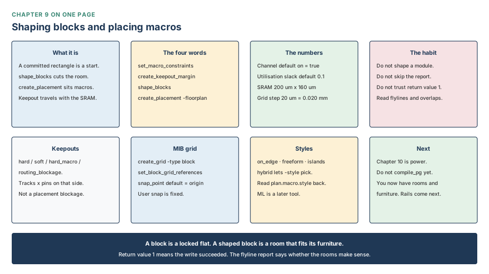
Why Chapter 10 follows
You now have rooms that are the right shape, and furniture that has a legal home. You do not yet have straps. A 40 µm channel is a corridor for signals and a corridor for power; this chapter borrowed a PG strategy only to derive a grid pitch, and it refused to compile the mesh. The next chapter takes these outlines and these macro locations and plans the power — rings, meshes, vias — through the same Nimbus-8 core of 10.24 mm² = 10,240,000 µm², without undoing the rooms you just cut. Do not compile PG because a grid needed a strategy. Compile PG when you mean the straps. That is why this chapter had to come first.