CHAPTER ELEVEN
Global Planning: The Channel You Left Is Where the Buses Live
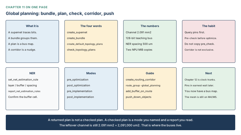
By the end of this chapter you will be able to group bus bits into supernets and bundles; to write a net estimation rule that does not sit on the power mesh; to turn that bundle into a topology plan of nodes and edges; to check the plan against the netlist before you optimize; and to treat a routing corridor as a nudge, not a locked door.
Why this chapter matters in a real project
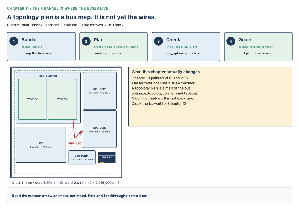
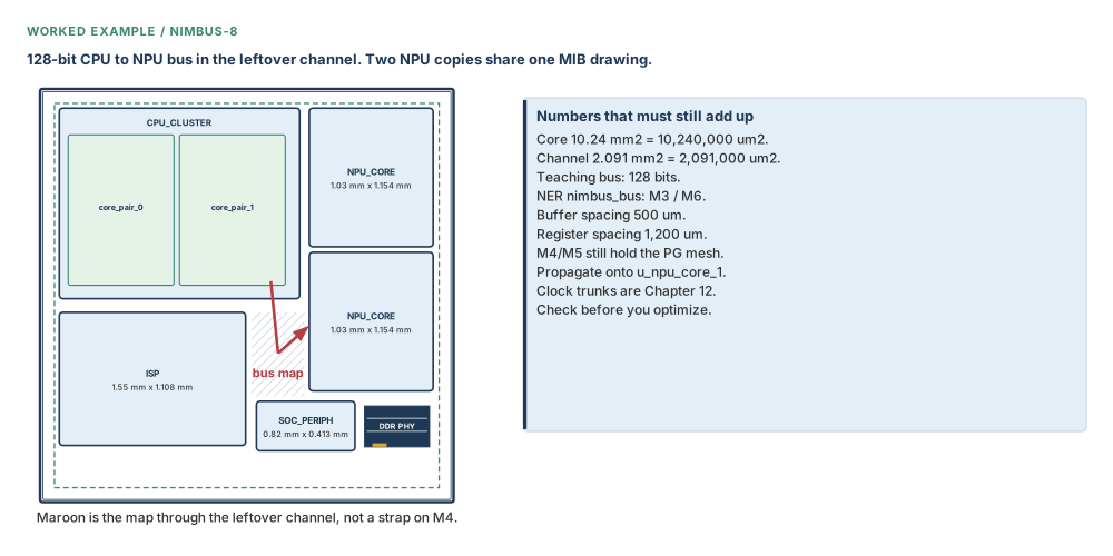
Sit with Nimbus-8 the morning after Chapter 10. VDD and VSS are metal. The ring walks M7 and M8. The mesh walks M4 and M5 at 20 µm. The cells can drink. And yet the chip still cannot talk to itself. The 128 bits that must run from the CPU cluster to an NPU copy have no agreed path through the leftover rooms. That leftover is not spare junk. It is 2.091 mm² = 2,091,000 µm² of channel, about a fifth of the 10.24 mm² = 10,240,000 µm² core, left empty on purpose so buses and glue can live there.
If you skip this chapter, two things happen and both are expensive. Either the router invents a bus path through a room you needed for something else, or you later spend a week drawing feedthroughs by hand. Global planning is the grown-up version of “which corridor does this bus walk?” You draw the map first. You check the map against the netlist. Only then do you ask the tool to walk it.
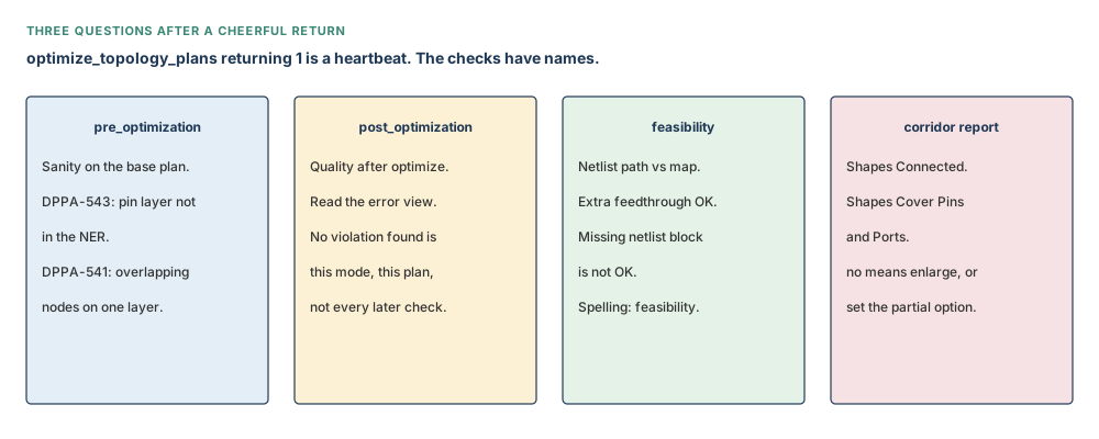
One more thing, because it will happen to you. You will type optimize_topology_plans. It will return 1. That means the walk finished. It does not mean the map matched the netlist, that every assigned pin sits inside a corridor, or that two NPU copies still share one drawing. Those are other commands.
Prerequisites
Chapter 10, because the mesh already occupies M4 and M5 and you must not park a bus on it. Chapter 9, because the rooms are shaped and the leftover channel is a measured number, not a feeling. Chapter 8, because a module is a name and a block is a physical room — topology nodes sit in rooms. Chapter 2, for the habit of reading back what you just set. The library is nimbus8.dlib. The top is NIMBUS8. Multiply instantiated block, then MIB: the two NPU copies share NPU_CORE.
How to read the numbers and the notation in this chapter
| You will see | Read it as | What you need to know |
|---|---|---|
| supernet | a tracing of bus bits | Named from the driver. May walk through feedthroughs and repeaters. Creating it does not route metal. |
| bundle | a group of supernets | Bits can be ordered. An empty bundle is a named box. |
| topology plan | the bus map | Nodes in rooms, edges through corridors. Still not the wires. |
| node / edge | a stop / a walk | End node sits at the centre of the end block if the endpoint is inside a block. |
| NER | net estimation rule | Layer, buffer, spacing. The recipe the plan eats. Report it back. |
| feedthrough | a walk through a room | The bus visits a block it does not terminate in. Needs a node in that room. |
| flyover | a walk over a room | Different permission from feedthrough. Set it on purpose. |
| corridor | a nudge for global routing | Not exclusive. Other nets may still enter. |
| complete / partial | pins inside / a pin outside | Shapes Cover Pins and Ports is the line to read. |
| M3 / M6 | teaching bus floors | Horizontal M3, vertical M6. Off the M4/M5 mesh, off M1 rails, off M2 streets. |
| 128 bits | the teaching CPU–NPU bus | Confirm the real pin names with get_pins before you type them. |
| MIB | multiply instantiated block | One drawing, more than one cell. Propagate the plan. Check alignment before push-down. |
Learning objectives
After this chapter you will be able to:
- Build a supernet from a queried driver and load, then bundle the bits.
- Write a net estimation rule on teaching layers that do not steal the power mesh, and report it back.
- Create a default topology plan for a named bundle, and know the command is plural.
- Run
check_topology_planswith a mode from the command page, not from a flow-picture nickname. - Tell a matching feasibility path from a missing-node mismatch.
- Optimize, then implement repeaters, without treating return 1 as tapeout.
- Propagate a plan onto the second NPU copy and check MIB alignment before push-down.
- Draw a routing corridor, read whether it covers pins, and globally route only the planned nets.
The beginner’s mental model
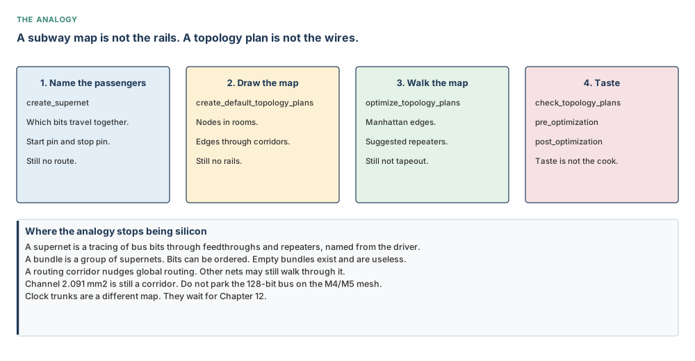
A subway map is not the rails
Hold a subway map next to a photograph of the tunnel. The map says “these stations, in this order, under these streets.” The photograph is dirt, concrete, and steel. A supernet names who is travelling. A bundle says they travel together. A topology plan is the map: nodes where the bus stops in a room, edges where it walks the corridor. optimize_topology_plans is the crew that walks the map and chalks repeater sites. None of that is the finished rails in the street.
The analogy stops being silicon quite quickly, and that is the point. A map can skip a station that the netlist still visits. A corridor can leave a pin outside its fence. Two NPU copies can share one drawing and still disagree about a track offset. A cheerful return value means the crew finished the walk. Tasting is a different command.
The precise engineering model
The database already has blocks, a leftover channel, and a compiled power grid. Global planning adds a second language on top of that geometry. A supernet is a tracing: start at a driver pin, stop at one or more load pins, walk transparently through repeaters and through cells you marked as transparent. A bundle is a homogeneous group of those tracings, so 128 bits can be ordered and planned as one family. A net estimation rule is the recipe the plan will eat: preferred layers, a buffer cell, a spacing in micrometres. A topology plan is then a graph. Nodes sit in rooms. Edges connect them. If the bundle already contains feedthroughs, the tool plants nodes inside those rooms when it builds the base plan.
Why bother? Because the traditional path — place pins, punch feedthroughs, sprinkle buffers, route the bus, each with its own constraint dialect — forces you to become five different operators. Unified topology constraints keep the intent in one object you can create, check, refine, optimize, write out, and propagate onto a multiply instantiated block.
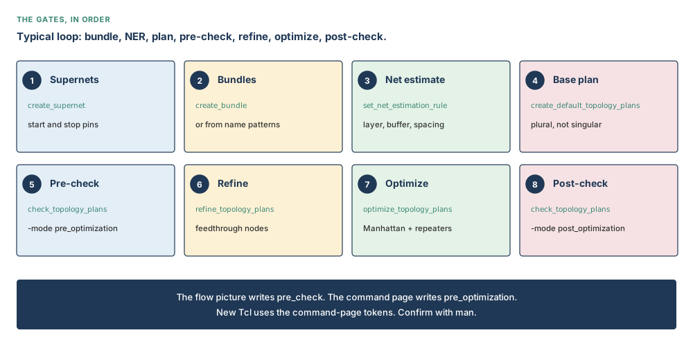
The practical loop is kind to beginners. Query the pins. Make the supernet and the bundle. Write the NER and report it. Create the default plan. Check it in pre_optimization. Refine if the walk is long. Optimize. Check it in post_optimization. If you also need a geometric nudge, add a routing corridor and globally route only those nets. Insert repeaters on that route. Allow feedthroughs. Push down. Legalise. Repair with ECO routing. Four small walks are easier to debug than one giant one.
Do not confuse these
| This | Is not | Hold this difference |
|---|---|---|
| Supernet | Bundle | A supernet traces bits. A bundle groups supernets so they can be planned as one family. |
| Topology plan | Routed metal | The plan is a map of nodes and edges. Optimize walks the map. Neither is a strap on M3 or M6. |
| NER | M4/M5 mesh | The net estimation rule is the bus recipe. The mesh already occupies M4 and M5. Teaching buses sit on M3/M6. |
pre_optimization | A flow-picture nickname | Type a mode from the command page. Do not invent a shorter name from a screenshot. |
| Complete corridor | Partial corridor | Complete means every assigned pin sits inside the shapes. Partial means a pin is outside and you said so on purpose. |
| Feedthrough | Flyover | A feedthrough visits a room. A flyover walks over it. They are different permissions. |
| Return 1 | Covered pins | Return 1 means the command finished. The cover-pins line is a different sentence. |
| Propagate | A second netlist | Propagate copies the plan onto the other MIB instance. It does not invent a second drawing of NPU_CORE. |
Concepts built from first principles
Part 1 — Supernets and bundles
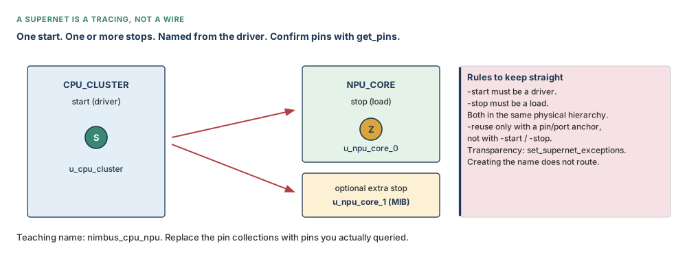
Start with one honest question: which bits travel together, from which driver, to which loads? A supernet answers that. You may give it one anchor pin or port, and the tool traces the physical hierarchy of that anchor. Or you give it a start and a stop. Or you give it one start and several stops. The start must be a driver. The stops must be loads. Both ends must sit in the same physical hierarchy. If a hierarchical term is offered, the tool picks the driver or the load for you — but you still queried the pin first, you did not invent it.
On Nimbus-8 the teaching bus is 128 bits from the CPU cluster toward an NPU copy, through the leftover channel. Do not type pin names from memory. Ask the design.
# Confirm driver and load pins with get_pins before you type them
icc2_shell> set cpu_drv [get_pins {u_cpu_cluster/cpu_npu_data_w[0]}]
icc2_shell> set npu_ld  [get_pins {u_npu_core_0/cpu_npu_data_r[0]}]
icc2_shell> create_supernet -name nimbus_cpu_npu -start $cpu_drv -stop $npu_ld
Those pin names are teaching stand-ins. Your netlist will differ. The shape of the command will not. -reuse is a different shape: it may be specified only with a pin-or-port anchor, not with -start / -stop. If a supernet with the same segments already exists, -reuse keeps it. Otherwise it creates. Default is false.
Repeaters are already transparent. Other cells are not, until you say so. set_supernet_exceptions marks pins, cells, or reference cells as transparent, or disables that marking. Hierarchical cells, library cells, and excluded cells are the vocabulary. You do this before the tracing, not after you are surprised.
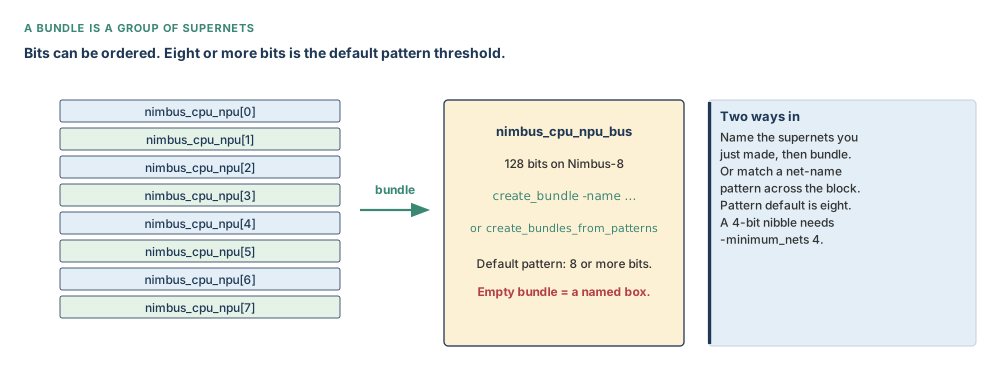
A bundle is then the group. create_bundle -name nimbus_cpu_npu_bus with no objects makes an empty named box, which is legal and useless. Pass the supernets you just made. Or let create_bundles_from_patterns match net-name groups. That command’s default is eight or more bits. A nibble of four will not bundle until you lower -minimum_nets. You can ignore braces, brackets, angle brackets, underlines, colons, or parentheses in the names. You can sort ascending or descending. You can cap the maximum. Prefix matching is how you keep the CPU–NPU family from swallowing an unrelated 128-bit test bus.
# Either name the supernets, or match a verified prefix. Do not run both.
icc2_shell> create_bundle -name nimbus_cpu_npu_bus [get_supernets nimbus_cpu_npu*]
# create_bundles_from_patterns -net_name_prefix cpu_npu_data -minimum_nets 128
Part 2 — Net estimation rules
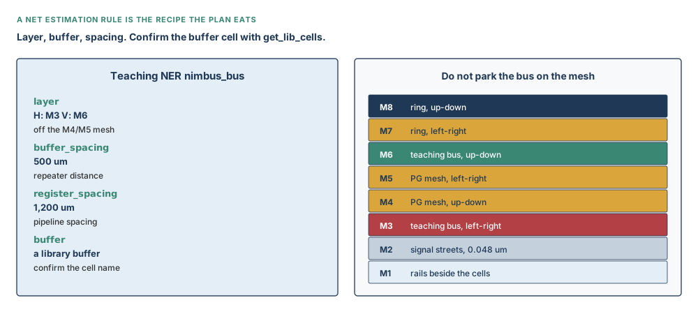
Before a topology plan can exist, it needs a recipe. A net estimation rule names the preferred layers, the buffer or inverter you want along the walk, the spacing between those buffers, and the spacing between pipeline registers. Horizontal and vertical may differ for layer. They must be set together: -horizontal_value comes with -vertical_value. A single -value applies to both directions. Report the rule. Do not trust the type-in.
On Nimbus-8 the power mesh already owns M4 and M5. M1 is rails. M2 is the dense signal street at 0.048 µm. The teaching bus therefore lives on M3 left-right and M6 up-down. That is a teaching choice you confirm against the library, not a law of physics. Buffer spacing 500 µm and register spacing 1,200 µm are the teaching distances. The buffer cell is whatever get_lib_cells says is a legal buffer in this library. Do not copy a cell name from another chip.
# Teaching NER. Confirm layers and the buffer cell against this library
icc2_shell> set_net_estimation_rule nimbus_bus -parameter "layer" \
    -horizontal_value "M3" -vertical_value "M6"
icc2_shell> set_net_estimation_rule nimbus_bus -parameter "buffer_spacing" \
    -value "500.000"
icc2_shell> set_net_estimation_rule nimbus_bus -parameter "register_spacing" \
    -value "1200.000"
icc2_shell> set_net_estimation_rule nimbus_bus -parameter "buffer" \
    -value $bufcell
icc2_shell> report_net_estimation_rules nimbus_bus
Other parameters exist: utilisation, derate, NDR, corner, capacitance, resistance. They are working knowledge. If you do not set a layer, the tool picks the middle of the current min and max routing layers. If you do not set a buffer, it chooses one. Unique rule names at the top of the hierarchy save you from a child block silently owning a different nimbus_bus.
Part 3 — Topology plans
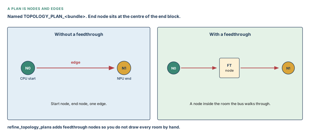
A topology plan is the map. create_default_topology_plans builds a base plan for one bundle, or for every bundle if you name none. Each base plan has a start node, an end node, and an edge. If the endpoint sits inside a block, the end node is planted at the centre of that block. If the bundle already contains feedthroughs, nodes appear inside those rooms. Generated names follow TOPOLOGY_PLAN_<bundle_name>.
The flow picture sometimes writes the command in the singular. The command page, and every example that actually returns a collection, use the plural. New Tcl uses the plural. Confirm with man.
# Base plan for the teaching bundle, eating nimbus_bus
icc2_shell> create_default_topology_plans -net_estimation_rule nimbus_bus \
    [get_bundles nimbus_cpu_npu_bus]
You may also build a plan by hand with create_topology_plan, plant nodes with create_topology_node, and join them with create_topology_edge. Floating nodes that never joined an edge can be tied in with create_topology_connections -style fishbone, or chain, or star, or a compass style. Fishbone is the teaching automatic: each floating node joins the nearest spine edge.
Feedthrough and flyover are permissions on the plan, not decorations. -allow_feedthrough is none, select_on, select_off, or all. The same four words exist for flyover. Type pure, mixed, or any when you mean a feedthrough type. Do not leave “the bus can go through anything” as an accident.
The plan you just created becomes current. current_topology_plan with no arguments returns it. With a name, it sets it. report_topology_plans writes the NER, the nodes, the edges, the repeater count. Use -verbose when you are debugging a node you cannot see.
Part 4 — Check, refine, and feasibility
This is the tasting that belongs before the long walk. check_topology_plans -mode pre_optimization is a sanity check on the base plan. The flow picture labels it pre_check. That nickname is not a legal mode. The command page lists four tokens: pre_optimization, post_optimization, pre_implementation, post_implementation. New Tcl uses those. Confirm with man.
icc2_shell> check_topology_plans -mode pre_optimization
When the check speaks, it speaks in DPPA numbers. DPPA-543: a node’s pins sit on a layer the NER does not include. DPPA-541: two nodes overlap and interleave pins on the same layer. DPPA-499: an edge overlaps a cell it is not allowed to feed through or fly over. DPPA-498: an edge is too close to a cell boundary. DPPA-497: two edges collide. DPPA-496 is the cousin of 543, still a layer-versus-NER fight. DPPA-495 warns that the bundle is wide and may need extra repeaters. DPPA-494 notes a pin order that disagrees with the bundle order. Read them. Revise the plan. Then optimize.
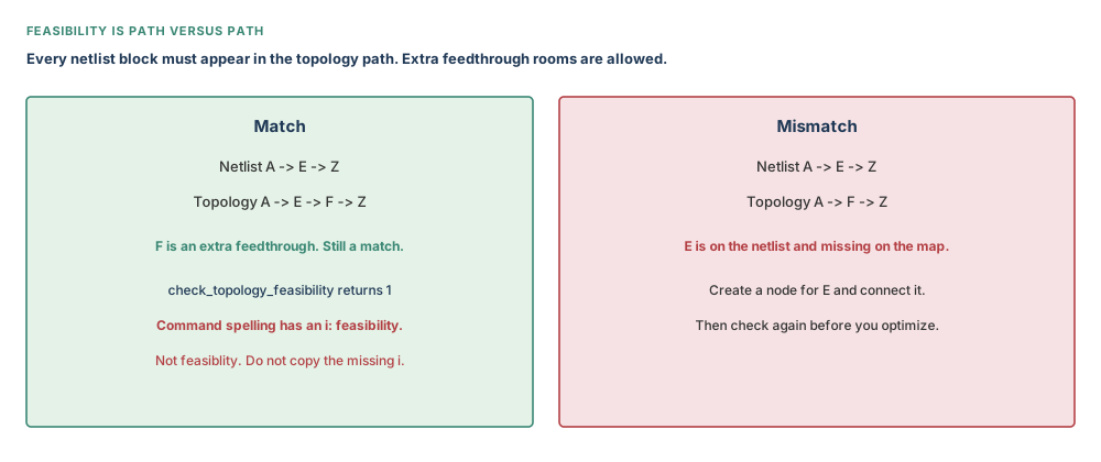
Feasibility is a different question: can this netlist path be implemented by this topology path? Extra feedthrough rooms on the map are allowed. A netlist room that the map skipped is not. The command is check_topology_feasibility, with an i. A nearby sentence in some notes drops that i. Do not copy the missing letter. Some examples also print a double prompt. Type the command once.
# Topology may add feedthrough F. It may not skip netlist block E
icc2_shell> check_topology_feasibility -plan T1 -from T1/A0 -to T1/Z0
If the map skipped E, the tool tells you to create a node that matches E/out and connect it. That is a missing station, not a routing DRC.
refine_topology_plans is the kindness for a long walk. Instead of planting every feedthrough node by hand, you refine. New nodes appear where Manhattan edge segments cut block boundaries — but only if the edge already has a layer-shape attribute in Manhattan style. Otherwise the command quietly creates nothing. Return 1 still happened. Inspect the node count.
Part 5 — Optimize and repeaters
Now the crew walks the map. optimize_topology_plans derives a Manhattan route, adds repeaters and sequential elements according to the NER, and, if the endpoint is a block or a feedthrough room, creates pins on that block. Return 1 means the walk finished. Then you taste with -mode post_optimization.
icc2_shell> optimize_topology_plans [get_topology_plans TOPOLOGY_PLAN_nimbus_cpu_npu_bus]
icc2_shell> check_topology_plans -mode post_optimization \
    [get_topology_plans TOPOLOGY_PLAN_nimbus_cpu_npu_bus]
-repeaters_only plants virtual register and buffer locations without adding nodes or edges. -no_route creates feedthroughs and pins from a plan that already has a complete routing topology. Neither is a waiver of the check.
Repeater optimization runs in two passes: honour the spacing, then legalise and insert extras where the first pass left a gap. By default the command honours physical and logical locations of repeaters that already exist. To stop that, set plan.interconnection.enforce_repeaters_hiers to false and read it back with report_app_options. Do not memorise a hidden default.
If part of a bundle’s hierarchy should be ignored — a room whose netlist you do not want to constrain this walk — set the user attribute stop_hierarchy on the bundle. create_default_topology_plans honours it. So does optimize, once the attribute is there.
icc2_shell> set_attribute [get_bundles nimbus_cpu_npu_bus] stop_hierarchy {u_isp}
Suggested repeaters on a plan are not yet cells. implement_topology_repeaters -topology_plans ... places existing registers first, then inserts buffers or inverter pairs. If register placement fails, buffers are not inserted. Default name prefixes are cir_cell and cir_net. remove_implement_topology_repeaters takes them back out. report_topology_plan_registers -type unimplemented is the default; -type all includes what is already bound. Unimplemented repeaters still have no objects attribute. That warning is information, not a crash.
Part 6 — Groups, propagate, write-out
Large chips cut the work into topology groups. create_topology_group -name ... -plans ... makes a named set. Plans with no group land in DEFAULT_TOPOLOGY_GROUP. current_topology_group reads or sets the current group. remove_topology_groups removes groups; -all is the wide broom. Removing a group does not, by itself, remove the plans unless you ask it to.
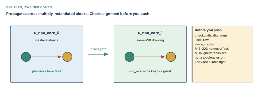
The two NPU copies share one multiply instantiated block drawing. Build the plan on the instance you can see, then propagate_topology_plans across the other copies in the current design. -no_overwrite keeps a destination that already has a plan. Without it, the guest is overwritten.
icc2_shell> propagate_topology_plans [get_topology_plans TOPOLOGY_PLAN_nimbus_cpu_npu_bus]
To rebuild the same maps in a cousin design, write them out. write_topology_plans -filename nimbus_topology.tcl emits Tcl. -log also writes the console. -include_objects adds bundle and supernet creation. -pins_locations writes side-node constraints with start and end offsets, so a similar chip that does not yet have pins can still receive the map. -current_block keeps the write inside the block you are in. The generated script will remove_topology_plans a name before recreating it. That is deliberate, not vandalism.
icc2_shell> write_topology_plans -pins_locations -include_objects \
    -filename nimbus_topology.tcl
Part 7 — Branching, ripping, bidirectional
Branching is the honest fan-out: every net in the bundle shares one driver block and the same load blocks. Ripping is the almost: most bits share the loads, one bit peels off. For ripping, build the plan so every load block — even the odd bit’s private load — has its own node, the driver has a node, and the graph is connected. Optimize will then group pins, honour spacing, associate pins with the correct node, and order them by bit order.
Bidirectional bundles interleave opposite directions to reduce crosstalk. All nets in that bundle must be supernets if you will run the topology commands on them. They must connect the same two leaf blocks, and they must keep order from driver to load or load to driver. Create the supernets, then bundle opposite directions together.
These three shapes are working knowledge you can name in an interview. They are not the first Nimbus-8 cook. The first cook is a one-way 128-bit walk through the leftover channel, checked, then optimized.
Part 8 — Routing corridors and global routes
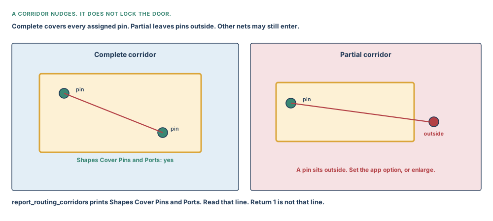
A topology plan is a map. A routing corridor is a fence you draw on the floorplan so global routing prefers that strip. During global routing, assigned nets are guided through the corridor. The corridor is not exclusive: other nets may still enter. You may set min and max layers, or inherit the design defaults. Optimization does not legalise cells inside a corridor.
Complete means the corridor encloses every pin of the assigned nets. Partial means at least one of those pins sits outside. Partial is legal. It is also how a report later says Shapes Cover Pins and Ports: no while the command still returned 1.
# Teaching rectangle in the leftover channel. Measure it on the floorplan
icc2_shell> create_routing_corridor -name nimbus_cpu_npu_corr \
    -boundary {{1760 1860} {2200 2560}} \
    -min_layer_name M3 -max_layer_name M6 \
    -object [get_nets cpu_npu_data*]
icc2_shell> report_routing_corridors [get_routing_corridors nimbus_cpu_npu_corr]
Those coordinates are a teaching box in micrometres. Confirm they sit in the hatched glue, not inside CPU_CLUSTER. The syntax line for -end_endcap sometimes grows a stray letter on the page. Do not type it. Endcaps are flush, half_width, or full_width.
You can add nets with add_to_routing_corridor, grow the shape with create_routing_corridor_shape, take nets out with remove_from_routing_corridor, and cut a piece with remove_routing_corridor_shapes. get_routing_corridors returns the collection.
Then globally route only those nets:
icc2_shell> route_group -global_planning true -nets [get_nets \
    -of_object [get_routing_corridors nimbus_cpu_npu_corr]]
-global_planning true makes the router virtually flat and hierarchy-aware: it will connect to pins inside child blocks, honour their blockages and preroutes, and can create pins on the next level down. Combined with -stop_after_global_route true it skips track assignment and detail routing. You must name the nets, or -all_clock_nets, or a file; -nets and -all_clock_nets are mutually exclusive. This command is for critical nets before signal routing. After signal routing, the repair tool is route_eco.
If the corridor is partial, set route.global.connect_pins_outside_routing_corridor to true so the router may reach the pins that sit outside. Read the option back. Complete corridors do not need that gift.
Part 9 — Repeaters on the route and push-down
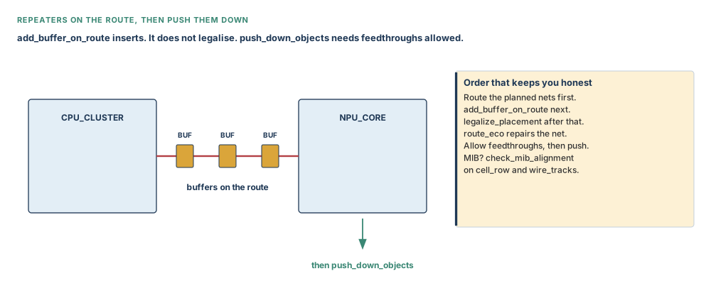
After the planned nets have a global route, you may insert repeaters on that route with add_buffer_on_route. That is a different insertion from topology-plan repeaters. It happens on the route, before objects are pushed into blocks and pins are punched.
# Confirm the lib_cell. Teaching distance 150 um
icc2_shell> add_buffer_on_route \
    -allow_insertion_over_cell [get_cells {u_cpu_cluster u_npu_core_0}] \
    -repeater_distance 150 -lib_cell $bufcell \
    [get_nets cpu_npu_data*]
The command detects inverter versus buffer from the library cell. It respects placement blockages and macros by default. -allow_insertion_over_cell is how you permit sitting on named blocks. -repeater_distance and -repeater_distance_length_ratio are mutually exclusive ways to space. You may scale by layer or by width. You may snap to sites. You may use it on incomplete routes. Many more options exist; this chapter does not invent them. See man.
Insertion is not legalisation. legalize_placement at top and in the blocks comes next. A net that changed needs route_eco to be whole again.
Then push. push_down_objects pushes top-level objects into blocks: nets, routes, vias, corridors, blockages, rows, and more. The object collection is required. To punch feedthroughs on a net:
icc2_shell> create_pin_constraint -type individual \
    -nets [get_nets cpu_npu_data*] -allow_feedthroughs true
icc2_shell> check_mib_alignment -cell_row -wire_tracks
icc2_shell> push_down_objects [get_nets cpu_npu_data*]
icc2_shell> push_down_objects [get_cells eco_*]
-type is required: individual or bundle. Feedthroughs default to whatever you do not say; say true when you mean them. For the two NPU copies, alignment against rows and tracks is optional in the flow and mandatory in judgement. MIB-203 names a track offset disagreement. That is not a topology-plan error. It is a later fight you want to see before you push.
Part 10 — Working knowledge
Name these without dumping flags. Shield placement on a default plan: outside, interleave, double_interleave, half_interleave. Segmenting an edge into pure H and V after refine or optimize: segmentize_topology_edge. What-if on layers: point the plan at a different NER and reoptimize. Clock trunks: Chapter 12. Full pin assignment: later. Do not drag those chapters backwards into this cook.
Inputs, outputs, and readiness
| Input | Why it matters | What you produce |
|---|---|---|
| Committed blocks and a leftover channel | Nodes sit in rooms. Buses walk the 2.091 mm² corridor, not through a sofa. | A named supernet bundle on a queried pin list |
| Compiled PG on M4/M5 | The teaching bus must choose other floors. | NER nimbus_bus on M3/M6, reported back |
| Library buffer cells | NER and add_buffer_on_route both need a real cell. | A buffer name from get_lib_cells, not from memory |
| MIB copies aligned, or a known offset | Push-down through NPU_CORE copies fails in ugly ways if tracks disagree. | check_mib_alignment transcript |
| A current block and a current plan | Create makes current. Report the wrong plan and you debug a ghost. | current_topology_plan / report_topology_plans |
Preflight checklist
- Leftover channel is the measured 2.091 mm² = 2,091,000 µm², not a feeling, and you can point at it on the die.
- Teaching bus layers are M3 horizontal and M6 vertical. They are not the M4/M5 mesh.
- Every pin you are about to name came from
get_pins, not from memory. - The two NPU copies are one MIB reference,
NPU_CORE, instancesu_npu_core_0andu_npu_core_1.
Guided tool workflow
| Step | Command | What you prove |
|---|---|---|
| 1 | get_pins / get_nets | The bits exist and you know their names |
| 2 | create_supernet / create_bundle | A tracing and a group, not yet a map |
| 3 | set_net_estimation_rule then report | Layers and spacing you would defend |
| 4 | create_default_topology_plans | A named plan with nodes and an edge |
| 5 | check_topology_plans -mode pre_optimization | Sanity, including DPPA layer fights |
| 6 | check_topology_feasibility | Netlist path is covered |
| 7 | refine_topology_plans if the walk is long | Feedthrough nodes you did not draw by hand |
| 8 | optimize_topology_plans then post-check | Manhattan edges and suggested repeaters |
| 9 | Optional corridor, route_group -global_planning true | Cover-pins line is yes, or the partial option is set |
| 10 | add_buffer_on_route, legalise, route_eco, push-down | Cells exist, then sit legally, then the net is whole, then they live in the rooms |
One continuous worked example
Nimbus-8, still. Core 3.20 mm × 3.20 mm = 10.24 mm² = 10,240,000 µm². Channel 2.091 mm² = 2,091,000 µm². Teaching bus: 128 bits, CPU cluster to u_npu_core_0, then propagate onto u_npu_core_1. NER nimbus_bus on M3/M6, buffer spacing 500 µm, register spacing 1,200 µm. Mesh on M4/M5 stays where Chapter 10 left it.
Query pins. Create one teaching supernet, then a bundle of the family. Write the NER and report it. Create the default plan for that bundle. Report the plan: you want a start node in the CPU room, an end node in the NPU room, and an edge that walks the leftover channel rather than diagonally through the ISP sofa. Pre-check. If DPPA-543 fires, the pin layer is not in the NER — fix the rule or the pin layer, do not ignore the number. Feasibility with an extra feedthrough through glue is a match. Feasibility that skips a netlist room is a mismatch. Optimize. Post-check. Propagate. Alignment. Only then a corridor in the measured glue, a route_group of those nets, buffers on the route, legalise, ECO, push-down.
Quiet success in this story is optimize_topology_plans returning 1 while the cover-pins line is still no, or while DPPA-495 is still warning that 128 bits are wide. Read the line. Do not argue with the heartbeat.
Failure modes and debugging
| What you see | Likely cause | What you inspect | What you do | The lesson |
|---|---|---|---|---|
| No metal after a beautiful plan | Optimize and route were never run | Shape browser; plan report | Optimize, then the corridor path if you need a nudge | A map is not rails |
pre_check is not a mode | Flow-picture nickname typed as Tcl | man check_topology_plans | Use pre_optimization | Command page wins this conflict |
Singular create_default_topology_plan fails | Flow picture dropped the s | Command page | Use the plural | Plural in new Tcl |
| DPPA-543 / 496 | Pin layer missing from the NER | NER report; pin layer | Add the layer or move the pin | NER is the recipe the node must eat |
| Feasibility skips E | Map has no node for a netlist room | From/to report | Create the node and connect it | Extra rooms OK; missing rooms not |
feasiblity is unknown | Missing i copied from a note | Command page | check_topology_feasibility | Spell the command |
-reuse rejected with -start | Reuse is only for a pin/port anchor | Syntax | Drop -reuse or switch shape | Two creation shapes |
| Empty bundle planned | No supernets passed | report_bundles | Fill the bundle | A name is not membership |
| Four-bit bus never bundled | Pattern default is eight | Pattern options | -minimum_nets 4 | Defaults are thresholds |
| Cover-pins is no | Partial corridor, or wrong box | report_routing_corridors | Enlarge, or set the partial app option | Return 1 is not that line |
| Other nets in your corridor | Corridors are not exclusive | Who is routed there | Accept, or add guides/blockages later | A nudge is not a lock |
| Buffers overlap sites | Insertion without legalise | Placement | legalize_placement then route_eco | Insert ≠ legal |
| MIB-203 on tracks | NPU copies disagree on offset | check_mib_alignment -wire_tracks | Fix alignment before push-down | Propagate is not alignment |
| Bus sitting on M4 | NER copied the mesh floor | NER report vs Chapter 10 | Move the teaching bus to M3/M6 | The channel is for buses; M4 is for PG |
Hands-on mini lab — Capella-6
Capella-6 is a new design, not Nimbus-8. The core is a square 700 µm = 0.700 mm on each side, so an area of 0.49 mm² = 490,000 µm². Two committed blocks sit left and right with a leftover strip between them. The teaching bus is 32 bits. Use NER layers M3 horizontal / M4 vertical — on this small lab the power mesh is not the Nimbus-8 mesh, so M4 is free here. Buffer spacing 200 µm.
Steps.
- Query a driver pin on the left block and a load pin on the right. Create a supernet. Bundle with
-minimum_nets 32if you use patterns, because 32 is above the default eight and you still want only this family. - Write NER
capella_buswith layer M3/M4,buffer_spacing200, a buffer cell you queried. Report the rule. - Create the default topology plan for that bundle. Report nodes and edges.
- Run
check_topology_plans -mode pre_optimization. Do not typepre_check. - Run feasibility from the start node to the end node.
- Optimize. Post-check. Read whether any DPPA message remains.
- Draw a corridor in the leftover strip. Report whether shapes cover pins. If no, enlarge or set the partial option. Globally route those nets with
-global_planning true.
Expected observations. The plan name follows TOPOLOGY_PLAN_<bundle>. Pre-check and post-check are different modes. A 32-bit bundle is wide enough for DPPA-495 to be worth reading. Return 1 after optimize can coexist with a cover-pins line of no.
Verification checklist. Pins were queried; NER layers are M3/M4; spacing is 200 µm; mode tokens match the command page; cover-pins was read; no conclusion rests only on return 1.
Stretch. Add a fake third room on the netlist path and omit it from the topology path. Record the feasibility message. Add the missing node. Check again.
Interview preparation
1. What is the difference between a supernet, a bundle, and a topology plan?
A supernet traces bits from a driver to loads; a bundle groups those tracings; a topology plan is the map of nodes and edges for that bundle.
A supernet is a tracing through the physical hierarchy, named from the driver, able to walk repeaters and transparent cells. Creating it does not draw metal. A bundle is a homogeneous group of supernets or nets so bits can be ordered and planned together. An empty bundle is a legal name with no passengers.
A topology plan is the map: start node, end node, edges, optional feedthrough nodes. Default plans are named TOPOLOGY_PLAN_<bundle>. The plan still does not route. Optimize walks the map. A corridor, later, only nudges global routing.
The interview-quality sequence is query pins → supernet → bundle → NER → plan → pre-check → optimize → post-check. Leaving out the query or the check turns a definition answer into an unsafe flow answer.
2. Why must you query pins before create_supernet?
Start must be a driver and stop must be a load in the same physical hierarchy; invented names are not a tracing.
The command will not forgive a load offered as a start. Hierarchical terms are resolved to driver or load, but only if the term exists. Teaching names in this chapter are stand-ins. On a real netlist you run get_pins and you pass collections.
-start / -stop is one creation shape. A single pin-or-port anchor is the other. -reuse belongs only to the pin-or-port shape. Copying -reuse onto a start/stop call is a syntax error, not a cleverness.
Transparency is a prior: repeaters are already transparent; other cells need set_supernet_exceptions if the tracing must walk through them.
3. What does optimize_topology_plans returning 1 prove?
It proves the optimize command completed; it does not prove the map matched the netlist, that DPPA checks are clean, or that a corridor covers pins.
Optimize derives a Manhattan route and may add repeaters and pins. Return 1 is command status. Pre-optimization sanity, post-optimization quality, feasibility, and the corridor cover-pins line are other sentences.
A senior answer names the mode tokens from the command page and refuses the flow-picture nicknames pre_check / post_check unless man on that build says otherwise.
This is the chapter’s quiet-success thread. A compiled PG mesh in Chapter 10 had the same shape: heartbeat versus taste.
4. Nimbus-8 has a 2.091 mm² channel and a 128-bit CPU–NPU bus. Where does the bus live?
In the leftover channel, on teaching layers M3/M6, not on the M4/M5 mesh and not through a block interior you still need.
The core is 10.24 mm² = 10,240,000 µm². About a fifth is channel: 2.091 mm² = 2,091,000 µm². That is the corridor Chapter 9 and Chapter 10 kept empty on purpose.
M4/M5 already carry the 20 µm power mesh. M1 is rails. M2 is the 0.048 µm signal street. The teaching NER therefore uses M3 horizontal and M6 vertical. Confirm those layers against the library. Do not silently upgrade the bus onto the mesh because “fat metal looks like a bus.”
128 bits packed on a 0.048 µm street would be only about 6 µm of tracks. Topology is not a width crisis on this die. Topology is which rooms the family is allowed to visit.
5. create_default_topology_plan or create_default_topology_plans?
The command is plural. The flow picture sometimes writes the singular. New Tcl uses the plural; confirm with man.
This is a named conflict, not a style choice. Examples that return a collection use create_default_topology_plans. Optional arguments include the NER name, feedthrough and flyover permissions, budgets, group, colour, and a bundle list. Omitting the bundle list means all bundles in the current design — which is a wide broom on a real chip.
Name both forms in an interview. Use the syntax form for new code. Do not “correct” an old script without knowing the build.
6. What is a net estimation rule for, in this chapter?
It is the recipe a topology plan eats: layers, buffer cell, buffer spacing, register spacing. Report it back.
set_net_estimation_rule sets one parameter per call. Horizontal and vertical layer values must be paired. A single -value applies to both directions. Buffer spacing 500 µm and register spacing 1,200 µm are the Nimbus-8 teaching distances. The buffer cell comes from the library.
If two NERs claim the same layer, the most recent wins. Child blocks may own a different rule of the same name; unique names at the top avoid that surprise.
The rule page also names other consumers. In this chapter the consumer is the topology plan. Confirm with man in your build rather than quoting a remembered feature list.
7. List the check_topology_plans modes and why the flow picture is a trap.
pre_optimization, post_optimization, pre_implementation, post_implementation. The flow picture writes pre_check and post_check, which are not those tokens.
Pre-optimization is sanity on the base plan: layer-versus-NER errors, overlapping nodes, illegal overlaps with cells, bundle width warnings, pin-order information. Post-optimization is quality after the walk. Implementation modes bracket implement_topology_repeaters.
Typing -mode pre_check is how a candidate shows they memorised a figure caption. Typing -mode pre_optimization is how they show they read the command. Confirm with man where you sit.
You may write findings to a file and to an error view. “No violation has been found” is that mode, that plan list, that moment.
8. When is a topology path still feasible if it does not match the netlist path exactly?
When the topology path includes every netlist block and may add extra feedthrough rooms. Skipping a netlist block is a mismatch.
A → E → Z on the netlist may be A → E → F → Z on the map. F is an extra station. That still matches. A → F → Z, dropping E, does not. The tool asks you to create a node that matches the missing pin and connect it.
The command is check_topology_feasibility. Notes nearby sometimes drop the i. Examples nearby sometimes print a double prompt. Type the real command once.
Feasibility is not DPPA sanity and not a corridor report. Three questions, three commands.
9. A routing corridor returned success but Shapes Cover Pins and Ports is no. What now?
The corridor is partial. Enlarge it to become complete, or set route.global.connect_pins_outside_routing_corridor to true and read it back.
Complete means every assigned pin sits inside. Partial means at least one sits outside. Both are legal corridor types. Global routing of assigned nets is guided through the corridor. Other nets may still enter; the corridor is not exclusive.
report_routing_corridors also prints whether shapes are connected. Either line can be no after a successful create. Return 1 created the object. The report describes the geometry.
Then route_group -global_planning true -nets ... on those nets. Name the nets. Do not use this command as post-signal ECO; that is route_eco.
10. How do topology-plan repeaters differ from add_buffer_on_route?
Plan repeaters are suggested on the map and later implemented from the plan; add_buffer_on_route inserts on an already globally routed net.
optimize_topology_plans can place virtual repeater sites from NER spacing. implement_topology_repeaters binds registers first, then inserts buffers. Failure to place registers stops buffer insertion. Default prefixes are cir_cell / cir_net. remove_implement_topology_repeaters undoes that implementation.
add_buffer_on_route runs after route_group in the corridor flow. It inserts on the route, respects blockages, may sit on named cells if you allow it, and does not legalise. You legalise, then route_eco, then push down.
Saying “I inserted repeaters” without saying which command is how an interview unravels. Name the object you edited: the plan, or the route.
11. What must be true before push_down_objects on an MIB?
Feedthroughs allowed on the net, objects named, and preferably check_mib_alignment on rows and tracks; propagate does not replace alignment.
create_pin_constraint -type individual -allow_feedthroughs true is the enable for punching feedthroughs. -type is required. Then push nets, then the repeater cells if you created them on top.
For u_npu_core_0 and u_npu_core_1, propagate_topology_plans copies the map. check_mib_alignment -cell_row -wire_tracks asks whether the copies still share rows and tracks. MIB-203 names an offset disagreement. Pushing through a disagreement is how a later chapter inherits a mess.
-no_overwrite on propagate keeps a destination that already has a plan. Without it, the guest is overwritten. That is a policy, not a default you should guess in an interview — say you set it on purpose.
12. You typed check_topology_plans -mode pre_check and the tool rejected it. Defend your next line.
Switch to pre_optimization, name the conflict, and confirm with man. Do not invent a third token.
The flow picture that introduces the chapter uses pre_check and post_check. The command page lists pre_optimization, post_optimization, pre_implementation, and post_implementation. This book’s new Tcl uses the command-page tokens.
A weak recovery is “I’ll try pre_opt.” A strong recovery is to quote both sources, pick the syntax list, and run man check_topology_plans on the build in the room.
The same muscle applies to the singular default-plan command and to feasiblity. Named conflicts are the chapter’s literacy test.
13. Optimize succeeded. Feasibility then says block E is missing. What is the repair?
Create a topology node that covers E’s pin and connect it into the path; do not reroute first and hope.
Optimize walked the map you gave it. Feasibility then compared that map with the netlist. If E is on the netlist and not on the map, the map is wrong. Adding a corridor will not plant a node in E. Adding buffers will not plant a node in E.
Create the node, connect the edge, re-check feasibility, then decide whether you must reoptimize. Refine can plant feedthrough nodes on a long Manhattan edge, but only if layer-shapes already exist. A skipped netlist room is a node you still owe.
Say that out loud: extra feedthrough F is allowed; missing E is not. Interviewers listen for that sentence.
14. A 128-bit bundle warns DPPA-495. Is the design illegal?
No. It is a width warning: extra repeaters may be needed to compensate timing differences among bits.
DPPA-495 is a warning, not the layer-versus-NER error. Wide bundles can skew. The NER’s buffer spacing is a single number; a single number may be insufficient on a bent walk. Read the warning, inspect bit order (DPPA-494), and inspect the register report after optimize.
Do not “fix” it by dropping to 32 bits in the netlist. Do not ignore it either. The grown-up move is to know it is a timing-uniformity warning on a family you chose to keep together.
On Nimbus-8, 128 bits through 2.091 mm² is a topology choice, not a track-count emergency. Keep those two worries apart.
15. You need the same CPU–NPU map on a cousin chip that has no pins yet. Which write option helps?
write_topology_plans -pins_locations writes side-node constraints with offsets so a similar design can rebuild the map before pins exist.
-filename captures Tcl. -log also prints. -include_objects brings bundles and supernets along. -current_block keeps the write local. -pins_locations is the one that swaps pin names for side and offset constraints.
The generated script will remove a like-named plan before recreating it. That is expected. Run it on a cousin, not blindly on the live Nimbus-8 session you still need.
Do not claim -output unless man shows it. This command’s file flag is -filename.
16. Global planning is done. Someone asks you to synthesize clock trunks in the same script. What do you say?
Clock trunk planning is the next chapter. This chapter ends with bus maps, corridors, and push-down of those nets.
The overall flow places global planning after the power network and before pin assignment and budgeting. Clock trunks have their own constraints, mapping file, endpoints, and push-down. Mixing them into this cook hides both plots.
What you can say, cleanly: the leftover channel now has a bus map; M4/M5 still hold PG; the two NPU copies can share a propagated plan; pins in earnest wait. Clock trunks start at the clock source and end at trunk endpoints. That sentence belongs in Chapter 12.
Breadth is naming the next chapter. Recklessness is pasting synthesize_clock_trunks into a topology script you have not checked.
Chapter close
Sign-off checklist for this planning stage
- Driver and load pins were queried, not invented.
- Supernets exist; the bundle is not empty; pattern thresholds were honest.
- NER
nimbus_busis M3/M6 (or the lab’s stated pair), reported back, buffer cell confirmed. - Default topology plan used the plural command and a named bundle.
- Pre-optimization used a command-page mode token, not
pre_check. - Feasibility covers every netlist room; extra feedthroughs are explained.
- Optimize return 1 was followed by post-optimization and a read of DPPA messages.
- MIB copies were propagated on purpose; alignment was checked before push-down.
- Any corridor’s cover-pins line was read; partial was a decision, not an accident.
- Clock trunks were not mixed into this script.
Key-concept flashcards
A topology plan is nodes and edges. Optimize walks it. Routing still has its own commands.
Supernet traces. Bundle groups. Empty bundle is a name.
optimize returning 1 is a heartbeat, not cover-pins and not feasibility.
pre_optimization, not pre_check. Confirm with man.
create_default_topology_plans. The picture’s singular is a conflict.
Bus on M3/M6. Mesh still on M4/M5. Rails on M1.
2.091 mm² = 2,091,000 µm². That is where the buses live.
Extra feedthrough OK. Missing netlist room not. Spell the i.
Nudge, not lock. Complete covers pins. Partial does not.
Propagate the plan. Align rows and tracks before push-down.
Plan repeaters versus add_buffer_on_route. Legalise after the route insertion.
Clock trunks are Chapter 12. Pins in earnest wait.
Compact glossary
| Term | Meaning as used in this book |
|---|---|
| Bundle | A homogeneous group of nets or supernets, optionally ordered. |
| Complete corridor | A routing corridor that encloses every pin of its assigned nets. |
| Feedthrough | A bus visit through a block that is not the endpoint. |
| Flyover | A permitted walk over a block without using it as a room. |
| NER | Net estimation rule: layers, buffer, spacings the plan will eat. |
| Partial corridor | A corridor with at least one assigned pin outside its fence. |
| Supernet | A tracing of bus bits from a driver through transparent cells to loads. |
| Topology edge | The walk between nodes, later Manhattanized by optimize. |
| Topology node | A stop in a room, or at the centre of an endpoint block. |
| Topology plan | The map for one bundle: nodes, edges, NER, permissions. |
Five-question self-check
Regulus-3 has a core that is a square 1,000 µm = 1.000 mm on each side, so an area of 1.00 mm² = 1,000,000 µm². Its teaching bus is 64 bits. NER buffer spacing is 250 µm.
- You have a driver pin and two load pins on the same physical hierarchy. Which
create_supernetshape do you use, and why is-reuseillegal on that call? - A flow note says
check_topology_plans -mode pre_check. What do you type instead, and which two further modes exist? - Netlist path is A → E → Z. Topology path is A → F → Z. Is that feasible? What do you add?
- A corridor creates successfully. The report says
Shapes Cover Pins and Ports: no. Name the corridor type and the two honest repairs. - Regulus-3 uses 250 µm buffer spacing across a 1,000 µm core. What is the first-order repeater count along a straight 1,000 µm edge, and why is it not a strap count?
Answers.
1. Use -start and -stop with the driver in start and the two loads in stop. -reuse may be specified only with a pin-or-port anchor, not with start/stop. Query the pins first.
2. Type -mode pre_optimization. The other documented modes are post_optimization, pre_implementation, and post_implementation. Confirm with man. Do not invent pre_check.
3. Not feasible: E is on the netlist and missing on the map. Extra F would have been legal in addition to E, not instead of E. Add a node covering E’s pin and connect it, then check again.
4. Partial. Enlarge the boundary until every assigned pin sits inside (complete), or set route.global.connect_pins_outside_routing_corridor to true and read it back. Return 1 did not cover the pins.
5. 1,000 / 250 = 4 spacings along a straight edge as first-order arithmetic, so a handful of repeaters, not 160 straps. Repeater spacing is a NER length along a bus. Strap count was Chapter 10’s mesh pitch. Do not copy 3,200 / 20 into this answer.
Why Chapter 12 follows
The leftover channel now has a bus map, and the mesh still holds power. What the chip still lacks is a coarse clock distribution from source to trunk endpoints that pin placement can honour. That is clock trunk planning. It is not a tail on optimize_topology_plans. This chapter ends with buses. The next begins at the clock port.