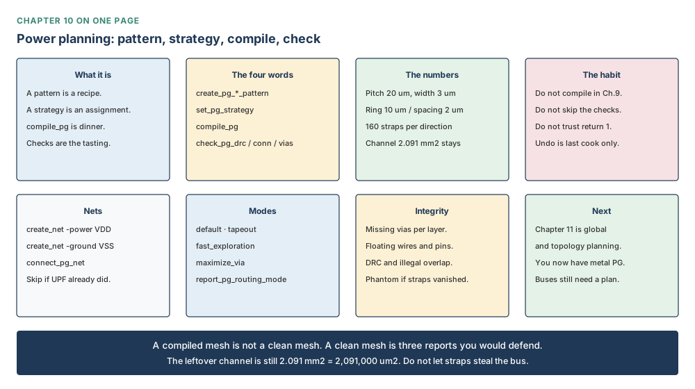
CHAPTER TEN
Power Planning: The Strategy You Defined Is Not Yet Metal on the Die
By the end of this chapter you will be able to wire VDD and VSS; to tell Metal 1 from Metal 2 from Metal 4; to read width, spacing, pitch and offset as four different lengths; to put a recipe on the core without thinking that is already metal; and to treat Successfully compiled PG. as a heartbeat, not a pass.
Why this chapter matters in a real project
Imagine you have just been handed Nimbus-8. The rooms are cut. The SRAMs are sitting down. Chapter 9 even wrote a power-grid recipe so the two NPU copies could share a 20 µm grid. Then it stopped. That recipe is still a card on the table. There is no metal on the die. The cells have nowhere to drink from. This chapter is the walk from “I know what I want the power grid to look like” to “the straps are actually there, and I have checked them.”
Sit with the die you already know. The core is a square 3.20 mm on each side, so an area of 10.24 mm² = 10,240,000 µm², at utilisation 0.617. The die is a square 3.44 mm on each side, so 11.83 mm² = 11,833,600 µm². A fifth of the core is still empty on purpose: the channel is 2.091 mm² = 2,091,000 µm². Power metal has to cross those rooms. It must not quietly steal that corridor.
One more thing, because it will happen to you. You will type compile_pg. The tool will print Successfully compiled PG. and return 1. That means the cook finished. It does not mean the meal is edible. Three other commands taste it: design-rule check, connectivity, missing vias.
Prerequisites
Chapter 9, because the furniture is already in the rooms. Chapter 8, because a module is a name and a block is a physical room — you plan power on the room. Chapter 4, for the die and the core. Chapter 2, for the habit of reading back what you just set. The library is nimbus8.dlib. The top is NIMBUS8.
How to read the numbers and the notation in this chapter
| You will see | Read it as | What you need to know |
|---|---|---|
| µm | microns, or micrometres | Every length you type. 1 mm = 1,000 µm. A ring width of 10 means 10 µm, not 10 mm. |
| width | how fat one strap is | The road, not the gap. Teaching mesh: 3 µm. |
| spacing | the empty gap to the neighbour | Grass between two roads. Teaching mesh: 3 µm. Not pitch. |
| pitch | how often the same net comes back | VDD to the next VDD. Teaching mesh: 20 µm. 3,200 / 20 = 160. |
| offset | the first step in from the edge | Where the first strap sits. Teaching mesh: 2 µm. Not width. |
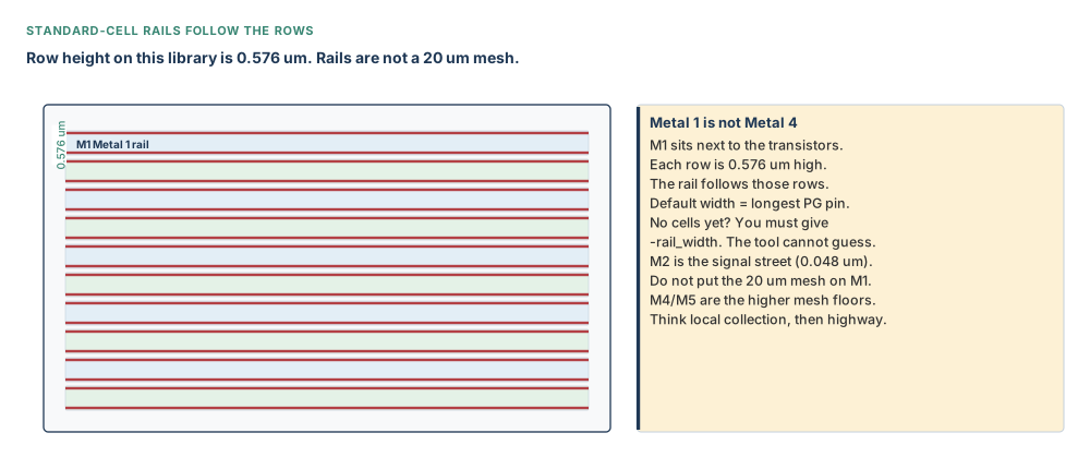
| Metal 1 / M1 | the ground floor, next to the cells | Standard-cell rails live here. One rail pair per 0.576 µm row. |
| Metal 2 / M2 | the next floor, signal streets | Track pitch 0.048 µm. We do not put the 20 µm power mesh here. |
| Metal 4 / M4 | a higher floor, up-down mesh | Vertical straps. Teaching width 3 µm, pitch 20 µm. |
| Metal 5 / M5 | the floor above that, left-right mesh | Horizontal straps. A via is the lift from M4 to M5. |
| Metal 7 / M8 | the ring floors | M7 walks left-right around the core. M8 walks up-down. Width 10 µm. |
| VDD / VSS | power / ground | Creating the name does not connect a pin to it. |
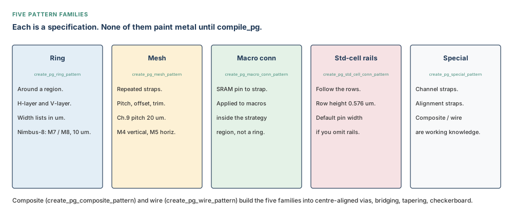
| pattern | the recipe card | Layers and lengths. No place on the die yet. |
| strategy | recipe plus kitchen | Which nets, which region. Still no metal. |
| compile | the cook | compile_pg is the first command that paints shapes. |
| MIB | multiply instantiated block | One drawing, more than one cell. Two NPU copies share NPU_CORE. |
Learning objectives
After this chapter you will be able to:
- Create VDD and VSS only if they do not already exist, then connect the pins.
- Point at Metal 1, Metal 2, Metal 4 and Metal 5 on a sandwich and say what each floor is for.
- Read width, spacing, pitch and offset out loud as four different sentences.
- Build the Nimbus-8 ring on M7/M8 and the mesh on M4/M5 without mixing those floors.
- Put a recipe on the core with a strategy, then admit that nothing is painted yet.
- Compile one strategy at a time. Know that
-undoremoves only the last cook. - Run three checks after the cheerful compile message, and treat early analysis as early.
- Know the names of the advanced tools without inventing their flags.
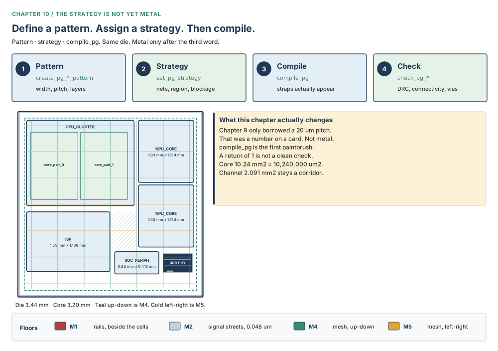
compile_pg. The legend under the die is the sandwich: M1 rails, M2 signal streets, M4 up-down mesh, M5 left-right mesh. Teaching purpose: one picture of the job, and which floor is which, before any command is typed.The beginner’s mental model
A recipe is not dinner
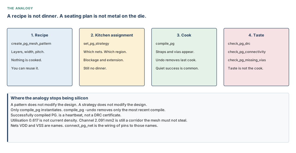
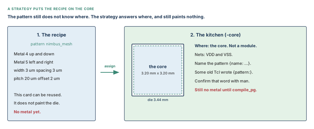
Sit with a recipe card next to an empty plate. The ring pattern is “use a 10 µm strip of Metal 7 and Metal 8 around the core.” The mesh pattern is “draw 3 µm roads on Metal 4 and Metal 5, every 20 µm.” The strategy is “cook that recipe on the core, and call the two roads VDD and VSS.” None of that is dinner. compile_pg is the person who actually puts food on the plate.
The analogy stops being silicon quite quickly, and that is the point. Metal has to obey spacing rules. It has to touch pins. Two floors only talk through a via. A beautiful recipe can still leave a SRAM thirsty. A cook can finish and still leave a missing via. That is why tasting is a different command from cooking.
The precise engineering model
Think of the chip as a sandwich. At the bottom sit the transistors, in rows 0.576 µm high. Metal 1 is the ground floor: tiny power rails that walk with those rows. Metal 2 is the next floor: dense signal streets, 0.048 µm apart on this library. We do not put the fat 20 µm power mesh there — that would be parking a lorry on a bicycle lane. Metal 4 and Metal 5 are higher floors where the mesh can be fat. Metal 7 and Metal 8 are higher still, where a ring can walk around the core. A via is a lift between two floors.
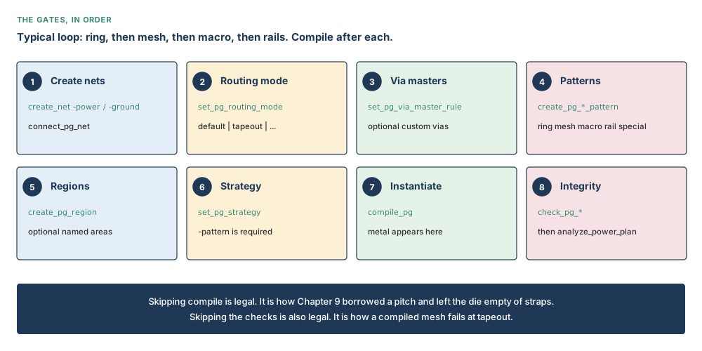
The database starts with names (VDD, VSS), pins on cells, a floorplan, and those empty floors. create_net writes a name if power intent has not already done so. connect_pg_net clips the cell pins onto that name. Pattern commands write a recipe. set_pg_strategy says which kitchen receives the recipe. compile_pg paints the metal. Then you taste.
Why all this metal? Voltage droops along a resistive road (IR). Too much current in too thin a road wears the metal (electromigration). And every power strap steals tracks the signals also wanted. There is no one formula. You choose width, pitch and vias, then you look. The practical loop is kind to beginners: ring, compile, check. Mesh, compile, check. Macro pins, compile, check. Rails, compile, check. Four small cooks are easier to debug than one giant one.
Do not confuse these
| This | Is not this | Why the mix-up is expensive |
|---|---|---|
create_net | connect_pg_net | The first creates a net object. It does not connect PG pins. |
| Pattern | Strategy | A pattern is geometry. A strategy adds region and real-net mapping. |
| Strategy | compile_pg | Chapter 9 defined one and stopped. Compile creates metal. |
| Module | Block | A module is logical hierarchy. A block is a physical design. Region choices that say blocks do not mean modules. |
| Mesh over a macro | Macro-pin connection | Crossing above a macro does not prove its PG pins are connected. |
| Mesh pitch | Standard-cell rail pitch | Nimbus-8 mesh pitch is 20 µm. M1 rails follow rows at 0.576 µm. |
{name: pattern_name} | {pattern: pattern_name} | Syntax uses name:; flow examples also show pattern:. Use name: in new Tcl and confirm with man. |
| Compile success | Clean PG | Successfully compiled PG. and return 1 do not replace three checks. |
compile_pg -undo | Undo all PG | It removes only the most recent compile_pg. |
analyze_power_plan | Sign-off IR analysis | It is early plan analysis, useful before later sign-off work. |
Concepts built from first principles
Part 1 — Create and connect power nets
First question, asked out loud: do VDD and VSS already exist? If committed power intent (UPF) created them, do not create them again. You will collide with a name that is already there. If they do not exist, create them. Either way, creating a name is not connecting a pin. A SRAM can sit next to a net called VDD and still be thirsty.
# Use create_net only when power intent has not already created these nets
icc2_shell> create_net -power VDD
icc2_shell> create_net -ground VSS
# Automatic is the default; spelling it out makes the teaching intent visible
icc2_shell> connect_pg_net -automatic -report_connection_summary true
Automatic connection is the default. It reads the power intent and the library pins and clips them together. You cannot mix it with a hand-written -net list on the same call. Manual connection exists for when you name the exact pins yourself. This chapter will not invent that list. Confirm the live switches with man connect_pg_net.
create_net -power VDD can succeed while every macro pin remains floating. The object exists. The electrical relationship does not, until connect_pg_net has done its job and connectivity is checked.
Part 2 — PG routing mode and via masters
set_pg_routing_mode -mode accepts default, tapeout, fast_exploration, and maximize_via. The modes change plan.pgroute.* application options. Read the mode back; do not invent a remembered default or copy hidden option values.
icc2_shell> set_pg_routing_mode -mode tapeout
icc2_shell> report_pg_routing_mode
tapeout aims for DRC-clean PG. fast_exploration trades completeness for speed and may skip DRC fixing of vias or disable via creation. maximize_via creates the maximum PG vias. Those are mode intentions, not a waiver from checking.
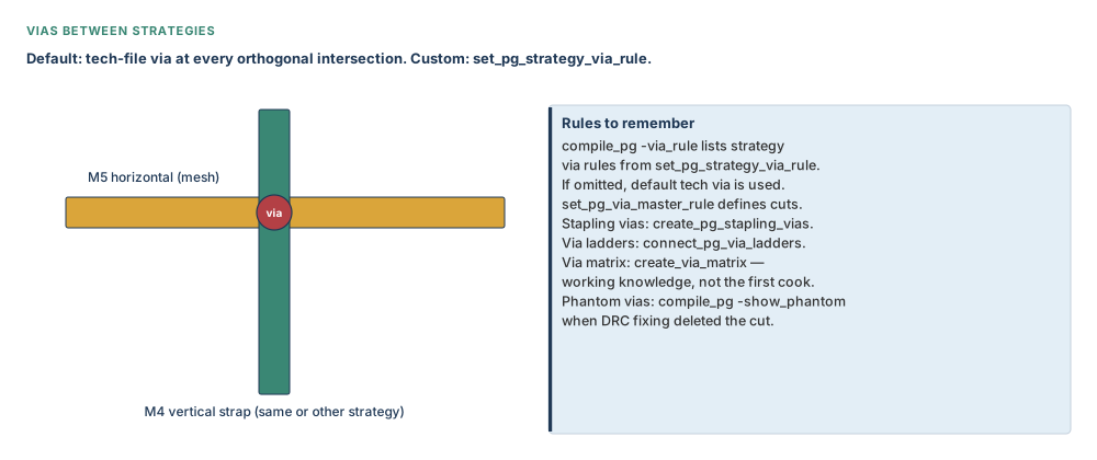
set_pg_via_master_rule exists for custom contact codes. This is working knowledge: default technology vias are used if you skip it. Confirm the exact custom-via syntax with man set_pg_via_master_rule; this chapter will not invent a contact-code example.
Part 3 — Ring patterns
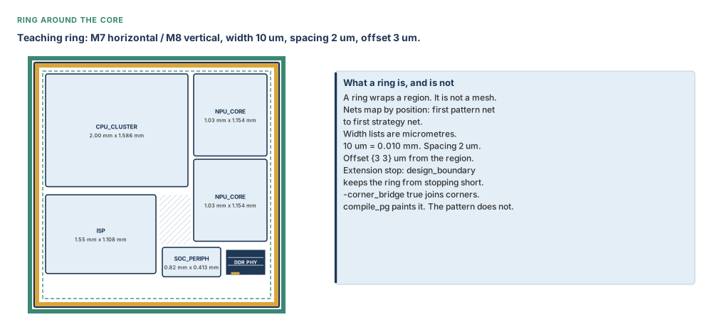
A ring is a picture frame. It walks around a region, not across it. On Nimbus-8 the left-right sides of the frame are Metal 7. The up-down sides are Metal 8. Each strip is 10 µm fat, with 2 µm of empty gap between VDD and VSS. The strategy later sits that frame 3 µm in from the core and lets it run out to the design boundary. The pattern itself still paints nothing.
# Nimbus-8 teaching ring; every length is in micrometres
icc2_shell> create_pg_ring_pattern nimbus_ring \
    -horizontal_layer M7 -horizontal_width {10} \
    -horizontal_spacing {2} \
    -vertical_layer M8 -vertical_width {10} \
    -vertical_spacing {2} -corner_bridge true
Parameters make a pattern reusable. Put @name where a value belongs, list names in -parameters, and pass values through the strategy’s {parameters: ...} in the same order. -track_alignment accepts track, half_track, or none. Use only when that alignment is an intentional constraint.
Part 4 — Mesh patterns
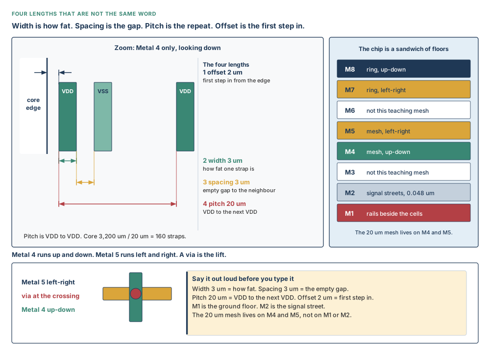
Now the four lengths. Beginners mash them into one word, “thickness.” They are four different sentences. Say them out loud while you look at Figure 10.6.
Width 3 µm is how fat one strap is. Think of a road. Not the grass. Not the next road. The tarmac. 3 µm = 0.003 mm.
Spacing 3 µm is the empty gap to the neighbour. VDD is 3 µm fat, then 3 µm of nothing, then VSS is 3 µm fat. Spacing is the nothing. It is a coincidence that width and spacing are both 3 on this teaching mesh. They do not have to match. Do not treat them as one number because they look similar.
Pitch 20 µm is how often the same net comes back. Centre of one VDD to centre of the next VDD. That is 20 µm = 0.020 mm. Across a core 3,200 µm wide: 3,200 / 20 = 160 straps per direction. Pitch is not width. Pitch is not spacing. Pitch is not “VDD to VSS.”
Offset 2 µm is the first step in from the core edge before the first strap starts. It is not a fourth name for width. If you type 2 thinking you made a fatter road, you only moved the first strap.
Which floor? Metal 4 runs up and down. Metal 5 runs left and right. Where they cross, a via is the lift. Metal 1 is the ground floor, for rails. Metal 2 is the signal street at 0.048 µm — leave it alone. This is the same 20 µm pitch Chapter 9 borrowed. Now it becomes metal.
# Chapter 9 borrowed this 20 um pitch. Chapter 10 paints it.
# width 3 um, spacing 3 um, pitch 20 um, offset 2 um
# Metal 4 up-down, Metal 5 left-right. Not Metal 1. Not Metal 2.
icc2_shell> create_pg_mesh_pattern nimbus_mesh -layers { \
    {{vertical_layer: M4} {width: 3} {spacing: 3} \
      {pitch: 20} {offset: 2}} \
    {{horizontal_layer: M5} {width: 3} {spacing: 3} \
      {pitch: 20} {offset: 2}} }
You may later see a production script with an interleaved mesh on M6/M7/M8. That is a different sandwich. Do not silently upgrade Nimbus-8. This teaching design stays on M4 and M5 at 20 µm so the Chapter 9 grid still means the same thing.
Part 5 — Macro connections and standard-cell rails
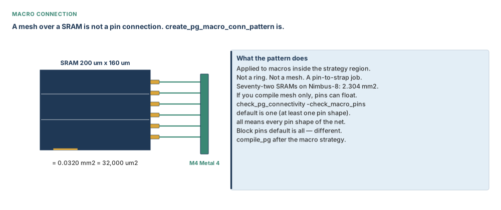
A macro connection pattern reaches PG pins. Required choices are -pin_conn_type and -layers. Pin types are long_pin, ring_pin, and scattered_pin. Direction, width, nets, and parameters are optional. Because Nimbus-8 library pin layers are library facts, the worked script uses a teaching long-pin connection on M4 and tells you to confirm that layer against the macro abstract.
# Confirm macro PG pin geometry before using this teaching layer
icc2_shell> create_pg_macro_conn_pattern nimbus_macro_conn \
    -pin_conn_type long_pin -direction vertical -layers {M4}
Standard-cell rails are a different floor and a different job. They live on Metal 1, next to the transistors, one pair per 0.576 µm row. They collect current locally. The M4/M5 mesh is the highway 20 µm away. If you copy pitch 20 onto Metal 1, most rows get no rail. Default rail width is the longest PG pin the tool can see. If there are no standard cells yet, you must give -rail_width — the tool has nothing to measure.
# M1 rails align with standard-cell PG pins and the 0.576 um rows
icc2_shell> create_pg_std_cell_conn_pattern nimbus_rails -layers {M1}
Optional rail controls include -rail_width {top bottom}, -rail_shift, masks, DRC checking, and marking as follow-pin. Defaults already align rails with standard-cell pins. Set an option only when you mean to change that contract.
Part 6 — Special, composite, and wire patterns
create_pg_special_pattern handles channel or alignment straps. create_pg_wire_pattern and create_pg_composite_pattern support shapes such as centre-aligned vias, bridging, via bridging, tapering, and checkerboards. create_pg_pattern_shapes and create_via_matrix are also working knowledge. These are useful when ring-plus-mesh-plus-connections cannot express the intended geometry. Confirm exact syntax with man; do not improvise flags from the feature names.
create_pg_strap and create_pg_vias are manual atomic tools. This chapter’s teaching path is pattern-based because reusable intent, strategy scoping, and staged compilation are easier to review than many one-off shapes.
Part 7 — Regions, strategy, blockage, and extension
The recipe still does not know which room to cook in. set_pg_strategy answers that. You pick exactly one region: the core, the design boundary, a voltage area, a polygon, some macros, some blocks, or a named PG region. One. Not two. And a block is still not a module.
# Ring: symbolic positions map to VDD VSS; offset is 3 um in x and y
icc2_shell> set_pg_strategy nimbus_ring_s -core \
    -pattern {{name: nimbus_ring} {nets: {VDD VSS}} \
              {offset: {3 3}}} \
    -extension {{stop: design_boundary}}
# Mesh: stop at the outermost ring and stay off hard macros
# Documented blockage shape is macros:{ cell cell }. Expand names first;
# extra braces would freeze a get_cells call as literal text.
icc2_shell> set hm [get_object_name [get_cells -hierarchical \
    -filter "is_hard_macro==true"]]
icc2_shell> set_pg_strategy nimbus_mesh_s -core \
    -pattern {{name: nimbus_mesh} {nets: {VDD VSS}}} \
    -extension {{stop: outermost_ring}} \
    -blockage [list macros: $hm]
The documented blockage shape is {macros:{ cell1 cell2 }}. Expand a collection into that list; extra braces freeze get_cells as literal text. Confirm the accepted expansion with man set_pg_strategy.
The pattern expression’s syntax uses {name: pattern_name}. Flow examples also write {pattern: mesh_pattern} for mesh and macro patterns. Name both forms when reviewing old Tcl; use {name: ...} in new Tcl and confirm with man set_pg_strategy on the build you run.
Extension stop tokens include first_target, innermost_ring, outermost_ring, pad_ring, design_boundary, design_boundary_and_generate_pin, and distance_in_microns. A blockage can name PG regions, blocks, macros, polygon, or voltage areas, with nets, layers, and area where appropriate. Use the simplest form your geometry requires.
create_pg_region, report_pg_regions, and remove_pg_regions -all manage reusable PG regions. The -tag on a strategy can support later organisation. Parameters passed through a strategy must remain in the same order as the pattern’s -parameters.
Part 8 — Instantiating with compile_pg
compile_pg is the cook. Until you type it, the die is still empty of straps. By default it cooks every strategy you have defined. While you are learning, name one. Cook the ring. Taste it. Then the mesh. Taste it. That way a burnt mesh does not hide inside a burnt everything.
icc2_shell> compile_pg -strategies nimbus_ring_s
icc2_shell> compile_pg -strategies nimbus_mesh_s -show_phantom
-show_phantom reports wires or vias that should have been created but failed DRC fixing. -ignore_drc and -ignore_via_drc are mutually exclusive. They do not make violations disappear; they alter what blocks creation. Signal routes are ignored for PG DRC by default. Set plan.pgroute.honor_signal_route_drc true when the flow requires PG to honour them.
compile_pg -undo removes only the most recent compile_pg. If you compiled ring, then mesh, then macro connections, one undo removes the macro-connection cook, not all PG and not the mesh. Tags can help organise a cook, but they do not change the one-level undo rule.
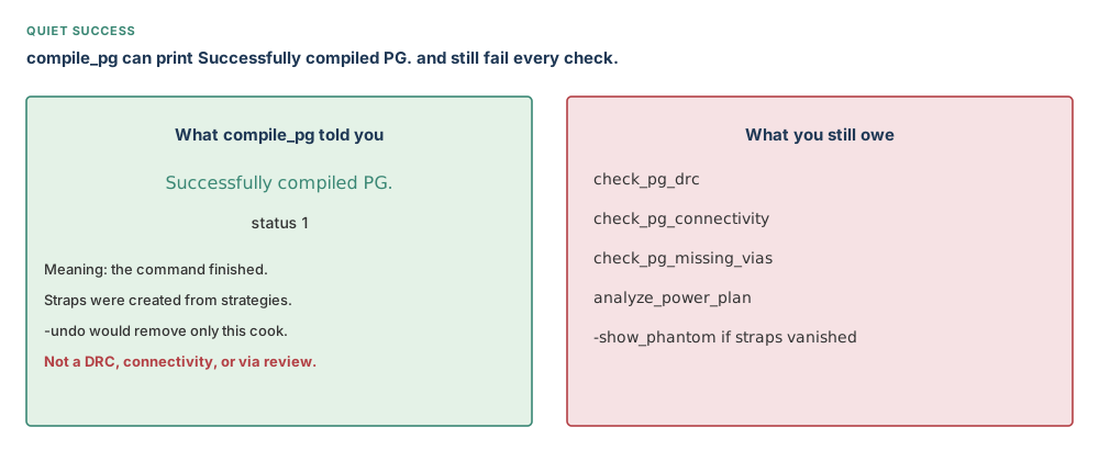
Successfully compiled PG. may coexist with failures in all three checks. Teaching purpose: make the chapter’s central trap impossible to miss.The compiler can finish every recipe it was able to instantiate and still leave spacing trouble, floating pin clusters, or absent vias. Read the message as “the command completed”. Never paraphrase it as “the mesh is clean”.
Part 9 — Integrity checks and analysis
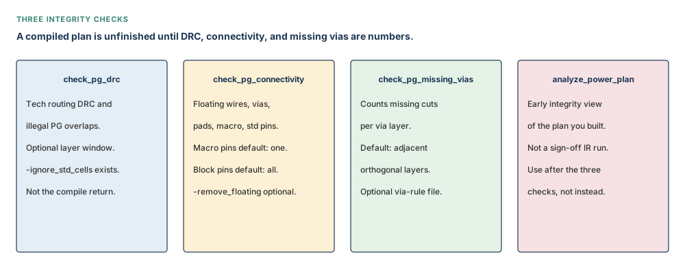
The three checks ask different questions. check_pg_drc asks whether PG geometry obeys rules. check_pg_connectivity asks whether wires, vias, and PG pins form the intended electrical graph. check_pg_missing_vias asks whether adjacent orthogonal-layer intersections lack expected vias.
icc2_shell> check_pg_drc -nets {VDD VSS} -no_gui -output nimbus8_pg_drc.rpt
icc2_shell> check_pg_connectivity -nets {VDD VSS} \
    -check_macro_pins all -check_std_cell_pins all \
    -error_view_name nimbus8_pg_conn
icc2_shell> check_pg_missing_vias -nets {VDD VSS} \
    -output_file nimbus8_missing_vias.rpt -filter_by_drc
icc2_shell> analyze_power_plan
Connectivity defaults matter: macro pins one, block pins all, pad pins one. State those defaults in an interview, then say when you would request all. Standard-cell pin checking is selectable too; this worked script requests all explicitly.
Missing-via checking defaults to adjacent orthogonal layers. Options can narrow a bounding box, honour blockages, ignore small intersections, or use a via-rule file. DRC checking can limit layers or coordinates and can include detailed-route shapes. Use only the filters that match the question; an aggressively filtered report is not a clean design.
analyze_power_plan is early analysis of the plan. It helps compare topology and metal choices before later sign-off analysis. It does not turn this chapter into sign-off IR closure.
Part 10 — Working knowledge: switches, trim, merge, stapling, ladders
trim_pg_mesh can trim rings, stripes, library-cell pin connections, macro-pin connections, or macro connections to a target wire or via. Default -trim_to is target_wire. DRC choices are no_check or check_but_no_fix. It has its own -undo. Confirm that your -types match the shapes you intend before trimming.
merge_pg_mesh, create_pg_stapling_vias, and connect_pg_via_ladders repair or consolidate specialised connectivity. create_power_switch_ring, create_power_switch_array, set_power_switch_placement_pattern, and connect_power_switch support switched supplies. Nimbus-8 is not switch-heavy, so these remain working knowledge. Confirm each syntax with man; do not infer flags from the command name.
generate_pg_script accepts input, input spreadsheet, output, run, and template paths. A syntax line prints -outut; the argument is -output. Use -output and confirm with man generate_pg_script. The PG Planning Task Assistant offers a GUI path; this chapter stays in the shell so every database transition is visible.
Distributed PG routing is available for larger work. Treat host setup and partition behaviour as working knowledge and confirm them locally. Early data checks can be managed with set_early_data_check_policy and report_early_data_checks; use them as an early warning layer, not as replacements for the integrity triad.
Mentor checkpoint 1: establish who owns VDD and VSS
Sit with the database before typing creation commands. There are only two sensible starting states:
- Committed power intent already created VDD and VSS. Skip
create_net. Continue to connection. - The nets do not exist. Create VDD as power and VSS as ground, then connect them.
The dangerous third state is uncertainty. Re-running creation because “the script always starts that way” can collide with power intent. Skipping connection because the names appear in a browser leaves pins floating. Ownership first, connection second.
A connection summary is evidence about logical PG relationships. It is not evidence that M4 meets M5 through a via or that an SRAM long pin reaches the mesh. Those questions become available after compilation.
Mentor checkpoint 2: choose a mode for the question being asked
If you are testing only whether a pattern covers the intended rooms, fast_exploration may be useful. Its speed has a price: via creation or via DRC fixing may be reduced. Do not compare its connectivity report with a tapeout-mode report as if the mode were irrelevant.
If you are preparing a result that should aim for DRC-clean PG, tapeout expresses that intention. If via redundancy is the explicit experiment, maximize_via expresses a different intention. default returns to the normal mode contract.
Whatever the choice, use the same three-step habit:
- Set the named mode.
- Report the mode.
- Record it beside the check reports.
That small record prevents a fast exploratory cook from being promoted accidentally as the final checked mesh.
Mentor checkpoint 3: read the ring as four sides, not one word
Nimbus-8’s teaching ring uses M7 for horizontal sides and M8 for vertical sides. Each listed width is 10 µm; each listed spacing is 2 µm. The strategy places the pattern at {3 3} µm and extends it to the design boundary. Corner bridging is true.
Each fact answers a separate review question:
- Which layers carry horizontal and vertical current?
- How much metal width is available?
- How much spacing separates VDD from VSS?
- Where does the pair sit relative to the core?
- How are turns at corners made continuous?
If an image looks like a ring but one side belongs to the wrong layer, it is not the specified ring. Geometry is reviewed by attributes and checks, not by colour alone.
Mentor checkpoint 4: preserve Chapter 9 mesh continuity
The mesh borrowed in Chapter 9 was not a placeholder to be silently upgraded. It was M4 vertical and M5 horizontal, width 3 µm, spacing 3 µm, pitch 20 µm, offset 2 µm. The block grid depended on that intent.
A flow-style interleaved M6/M7/M8 mesh can be a useful alternative complete-script shape. It is not the Nimbus-8 teaching mesh. Changing to it would change layer use, via interfaces, and the relationship with the ring. That is a new design decision, not formatting.
Use the simple arithmetic as a review alarm:
- Core side: 3,200 µm.
- Pitch: 20 µm.
- Planning count: 3,200 / 20 = 160 straps per direction.
If a report or picture suggests twenty straps, someone probably copied the Altair-5 pitch or counted the wrong structure.
Mentor checkpoint 5: protect macros, then reconnect them deliberately
A macro blockage keeps regular mesh straps away from macro area. That protects routing and pin-access resources, but it also creates an electrical obligation: the macro still needs a path to VDD and VSS.
The macro-connection pattern fulfils that obligation. Choose long_pin, ring_pin, or scattered_pin from the actual abstract. Choose layers from the same evidence. A command that parses with the wrong type can still create an unhelpful pattern object.
Review in this order:
- Confirm macro PG pin geometry.
- Confirm the mesh blockage does not pretend to be a connection.
- Compile the macro strategy separately.
- Check macro pins with
all.
Nimbus-8 contains 72 SRAMs at 0.0320 mm² = 32,000 µm² each, totalling 2.304 mm² = 2,304,000 µm². A connectivity shortcut repeated over that many macros is not a small shortcut.
Mentor checkpoint 6: let rails follow rows
The row is 0.576 µm high. The rail pattern aligns with standard-cell PG pins on those rows. The higher M4/M5 mesh is spaced at 20 µm. One is local collection; the other is distribution.
If cells already exist, the default rail width comes from the longest PG pin. If no cells exist, there is no pin to inspect, so -rail_width is required. That requirement is not an inconvenience to bypass with a guessed number. Obtain the intended rail dimensions from the technology and library setup, then confirm them with man and the database.
Shift 0 centres a rail at the row boundary. A positive shift moves it into rows. Use a non-zero shift only when the cell-pin geometry requires it and the DRC consequences are understood.
Mentor checkpoint 7: make strategy scope visible
Every strategy must answer “where?”. Core, design boundary, voltage areas, polygon, macros, blocks, and PG regions are distinct answers, and only one region selector belongs on a strategy.
Then answer four more questions:
- Which symbolic positions become VDD and VSS?
- What parameter values replace any
@nameplaceholders? - What areas must be blocked?
- Where do generated shapes stop?
A block selector refers to a physical design. It does not turn a logical module into a block. That distinction survives every chapter.
For new Tcl, the pattern expression uses {name: ...}. When an older example uses {pattern: ...}, do not hide the conflict. Confirm the accepted form with man set_pg_strategy on the running build.
Mentor checkpoint 8: compile in slices
Compile the ring alone. Check it. Compile the mesh alone. Check it. Compile macro connections alone. Check them. Compile rails alone. Check them. This is not ceremony; it is fault isolation.
If everything is compiled at once and macro pins float, possible causes include connection, blockage, pin type, pin layer, via suppression, or extension. If macro connections were the most recent isolated cook, the search space is smaller.
-show_phantom adds evidence about shapes that should have existed but failed DRC fixing. It should be read alongside, not instead of, DRC and missing-via reports.
Keep an explicit compile ledger:
- Strategy name.
- Routing mode.
- Compile status.
- Phantom observations.
- Three check report names and finding counts.
Then compile_pg -undo has a known target: the last line in that ledger.
Mentor checkpoint 9: interpret the three checks together
A DRC-clean wire can float. A connected path can violate spacing. Two orthogonal shapes can each be legal yet miss the via that joins them. That is why no single check dominates the other two.
Start broad enough to expose the problem. Narrow by net, coordinate, layer, or bounding box only after the first evidence points to a region. Keep the broad report so the narrowed debug run cannot be mistaken for full-design closure.
Connectivity pin defaults are part of the result:
- Macro pins: one.
- Block pins: all.
- Pad pins: one.
When reviewing every macro connection, request macro pins all. When reviewing pad closure, request pad pins all. Defaults are useful starting points, not universal coverage claims.
Mentor checkpoint 10: know where working knowledge stops
Trim, merge, stapling vias, via ladders, switch rings, switch arrays, pattern-shape creation, via matrices, distributed routing, and script generation belong in the wider PG toolbox. They solve real problems. They are not reasons to invent option lists.
State the job each family performs, then use man before typing. For generate_pg_script, the known spelling conflict is explicit: use -output, not the printed -outut. For custom via masters, confirm contact-code syntax locally.
The GUI Task Assistant can help organise PG planning, but shell commands remain the teaching path because the pattern, strategy, compile, and check boundaries are visible in the transcript.
Inputs, outputs, and readiness
| Stage | Needs | Writes |
|---|---|---|
| Nets | Committed UPF, or a decision that nets do not yet exist | Net objects only; creation does not connect pins. |
| PG connection | Power intent and libraries with PG pins for automatic mode | Pin-to-net connectivity; no wires or vias. |
| Patterns | Technology layers and intentional dimensions | Reusable recipe objects; no region and no metal. |
| Strategies | Pattern, exactly one region, real nets | Placement intent, parameters, offsets, extension, blockage; still no metal. |
| Compile | Defined strategy and connected nets | PG wires and vias in the design database. |
| Macro connection | Actual macro PG pin type and layer | Shapes that reach macro pins after compile. |
| Rails | Rows and standard-cell PG pins, or explicit width if no cells exist | M1 follow-pin-style rails after compile. |
| Integrity checks | Compiled PG | Reports and optional error views; they do not repair the plan. |
| Early analysis | A plausible connected plan | Planning evidence, not sign-off IR closure. |
Preflight checklist
nimbus8.dliband topNIMBUS8are open; the core and placed macros match Chapter 9.- VDD and VSS exist once. If UPF created them, no duplicate
create_net. connect_pg_netsummary matches committed power intent and PG-capable libraries.- Routing mode was set intentionally and read back.
- Ring is M7/M8, 10 µm wide, 2 µm spacing, offset {3 3} µm.
- Teaching mesh is M4/M5, width 3 µm, spacing 3 µm, pitch 20 µm, offset 2 µm.
- Macro connection matches real pin geometry. M1 rails follow 0.576 µm rows.
- Hard macros and blocks are not confused with modules in blockages or regions.
- One strategy will compile at a time; reports have unique names.
- Three checks are planned after every meaningful cook, not only at the end.
Guided tool workflow
- Open
nimbus8.dlib, current topNIMBUS8, and confirm the 3.20 mm × 3.20 mm core. - Create VDD/VSS only if UPF did not. Connect PG pins automatically and request a summary.
- Set
tapeoutmode for this teaching run and report it. - Define the M7/M8 ring, map VDD/VSS at offset {3 3}, stop at the design boundary, compile only the ring, check.
- Define the continuous M4/M5 mesh at 20 µm pitch, block hard macros, stop at the outermost ring, compile only the mesh, check.
- Define a macro-connection pattern from actual macro pin geometry, strategy on macros, compile, check connectivity with all macro pins.
- Define M1 rails, strategy on core, compile, check all standard-cell pins.
- Run missing-via check and early power-plan analysis. Inspect reports before accepting the cheerful compile lines.
What to record at each gate
A reproducible PG review is a sequence of small records. Sit beside the beginner and write the evidence down while the commands are still fresh.
Gate A — net and pin ownership
- Did committed UPF create VDD and VSS?
- If Tcl created them, were VDD and VSS marked power and ground respectively?
- Was automatic connection supported by committed power intent and PG-aware libraries?
- Did the connection summary identify anything unexpected?
This gate contains no claim about metal. Its output is logical ownership and connection intent.
Gate B — reusable geometry
- Ring directions: M7 horizontal and M8 vertical.
- Ring dimensions: width 10 µm, spacing 2 µm.
- Mesh directions: M4 vertical and M5 horizontal.
- Mesh dimensions: width 3 µm, spacing 3 µm, pitch 20 µm, offset 2 µm.
- Rail layer: M1, interpreted against 0.576 µm rows.
This gate contains pattern objects. It still contains no claim that the die has those shapes.
Gate C — placement intent
- Ring strategy maps symbolic positions to {VDD VSS}, offset {3 3} µm, stop design boundary.
- Mesh strategy maps {VDD VSS}, blocks hard macros, stop outermost ring.
- Macro strategy points at physical hard-macro cells, not logical module names.
- Rail strategy covers the intended core rows.
Record whether the active build accepts {name: ...} as expected. If old Tcl used {pattern: ...}, record that as a compatibility observation rather than silently mixing styles.
Gate D — instantiated shapes
- Compile only the named strategy.
- Record the routing mode beside the compile.
- Record the status line without interpreting it as a check.
- Inspect phantom wires and vias when requested.
- Note which cook is now the one removable by
compile_pg -undo.
At this gate, wires and vias finally exist. Their existence is not yet evidence that they are legal or connected.
Gate E — integrity
- DRC report: finding count, affected layers, affected nets, and bounding regions.
- Connectivity report: pin classes requested and floating clusters found.
- Missing-via report: true omissions versus DRC-filtered or intentionally blocked intersections.
- Early analysis: observed plan trend, labelled clearly as non-sign-off.
If any finding is accepted temporarily, give it an owner and a reason. “Compile returned 1” is neither.
Routability conversation before denser metal
A beginner often sees an IR concern and reaches first for more straps. More metal may help delivery, but it also consumes tracks and creates more intersections needing vias. On Nimbus-8, the channel is 2.091 mm² = 2,091,000 µm², or 20.4 per cent of the core. Chapter 9 protected it for a reason.
Before reducing pitch, ask:
- Is the observed weakness a disconnected macro, rather than insufficient mesh density?
- Are missing vias preventing the present mesh from behaving as intended?
- Would wider straps or stronger via population address the local concern with less routing cost?
- Does the proposed layer change collide with signal corridors or the M7/M8 ring?
- Will the MIB grid assumptions inherited from the 20 µm pitch remain valid?
No invented formula replaces that conversation. Use early analysis to compare plans, then preserve room for later sign-off work.
Reading a quiet transcript correctly
A useful transcript may look uneventful:
icc2_shell> compile_pg -strategies nimbus_mesh_s -show_phantom
# Successfully compiled PG.
# Return value: 1
# Continue: read phantom output and run three checks
The first line is an action. The next two are status. The final comment is engineering process. If a check then reports a missing M4–M5 via, the transcript is not contradictory. The compiler completed and the integrity check found a defect.
That distinction is what makes automation safe. A script should treat command completion and acceptance criteria as separate gates, just as the mentor does.
Stop conditions before the worked example
Pause the flow and debug when any of these statements is true:
- VDD or VSS has uncertain ownership between UPF and Tcl.
- The PG connection summary does not match the intended domains.
- The reported routing mode is not the mode selected for this run.
- The Nimbus-8 mesh no longer matches M4/M5 at 20 µm pitch.
- A strategy points at a module name where a physical block or cell is required.
- A macro blockage exists without a reviewed macro-connection path.
- A rail pattern is inferred in a design that has no standard cells.
- Phantom shapes appear and no one has classified them.
- One of the three integrity reports has not been read.
- The only evidence offered is
Successfully compiled PG.or return 1.
Continue when the opposite evidence is recorded:
- Nets exist once and PG pins are connected.
- Pattern dimensions and layer directions match the teaching plan.
- Strategies have one region, explicit real nets, and deliberate stopping and avoidance.
- Each cook has a known scope and a known one-level undo target.
- DRC, connectivity, and missing-via findings are zero or have a specific debug owner.
This is not a request for approval. It is a technical readiness boundary: facts before the next database mutation.
Eight-point treatment of the commands that matter
Each row records purpose, key options, defaults, units, what changes in the database, what does not, the return or quiet-success trap, and a companion report or check. Additional syntax belongs behind man <command>; no flag should be guessed from memory.
| Command | The eight points |
|---|---|
| create_net / connect_pg_net |
|
| create_pg_ring_pattern |
|
| create_pg_mesh_pattern |
|
| create_pg_macro_conn_pattern |
|
| create_pg_std_cell_conn_pattern |
|
| set_pg_strategy |
|
| compile_pg |
|
| check_pg_drc / conn / missing_vias |
|
One continuous worked example
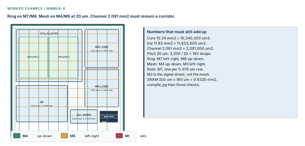
Situation. Nimbus-8’s rooms and macros exist in nimbus8.dlib, top NIMBUS8. u_cpu_cluster is 2.00 mm × 1.586 mm = 3.172 mm² = 3,172,000 µm² and parents u_core_pair_0 and u_core_pair_1. u_npu_core_0 and u_npu_core_1 are a multiply instantiated block (MIB), reference NPU_CORE, each 1.03 mm × 1.154 mm = 1.189 mm² = 1,189,000 µm². u_isp is 1.55 mm × 1.108 mm = 1.717 mm² = 1,717,000 µm². u_soc_periph is 0.82 mm × 0.413 mm = 0.339 mm² = 339,000 µm².
Seventy-two SRAMs, each 200 µm × 160 µm = 32,000 µm² = 0.0320 mm², occupy 2.304 mm² = 2,304,000 µm². The DDR PHY is 1.60 mm × 0.34 mm = 0.544 mm² = 544,000 µm². The ring, mesh, macro connections, and M1 rails must reach these loads without erasing the 2.091 mm² = 2,091,000 µm² channel story.
# Nimbus-8 pattern-based PG script
# Library nimbus8.dlib; top NIMBUS8
# Core 3,200 um × 3,200 um = 10.24 mm² = 10,240,000 µm²
# Create only if committed UPF did not already create these nets
icc2_shell> create_net -power VDD
icc2_shell> create_net -ground VSS
icc2_shell> connect_pg_net -automatic -report_connection_summary true
icc2_shell> set_pg_routing_mode -mode tapeout
icc2_shell> report_pg_routing_mode
# Ring: M7 horizontal, M8 vertical, width 10 um, spacing 2 um
icc2_shell> create_pg_ring_pattern nimbus_ring \
    -horizontal_layer M7 -horizontal_width {10} \
    -horizontal_spacing {2} \
    -vertical_layer M8 -vertical_width {10} \
    -vertical_spacing {2} -corner_bridge true
icc2_shell> set_pg_strategy nimbus_ring_s -core \
    -pattern {{name: nimbus_ring} {nets: {VDD VSS}} \
              {offset: {3 3}}} \
    -extension {{stop: design_boundary}}
icc2_shell> compile_pg -strategies nimbus_ring_s
icc2_shell> check_pg_drc -nets {VDD VSS} -no_gui \
    -output nimbus8_ring_drc.rpt
icc2_shell> check_pg_connectivity -nets {VDD VSS} \
    -check_macro_pins one -check_block_pins all \
    -check_pad_pins one -error_view_name nimbus8_ring_conn
# Mesh continuity with Chapter 9:
# M4 vertical / M5 horizontal, width 3 um, spacing 3 um
# pitch 20 um, offset 2 um; 3,200 / 20 = 160 straps per direction
icc2_shell> create_pg_mesh_pattern nimbus_mesh -layers { \
    {{vertical_layer: M4} {width: 3} {spacing: 3} \
      {pitch: 20} {offset: 2}} \
    {{horizontal_layer: M5} {width: 3} {spacing: 3} \
      {pitch: 20} {offset: 2}} }
icc2_shell> set hm [get_object_name [get_cells -hierarchical \
    -filter "is_hard_macro==true"]]
icc2_shell> set_pg_strategy nimbus_mesh_s -core \
    -pattern {{name: nimbus_mesh} {nets: {VDD VSS}}} \
    -extension {{stop: outermost_ring}} \
    -blockage [list macros: $hm]
icc2_shell> compile_pg -strategies nimbus_mesh_s -show_phantom
icc2_shell> check_pg_drc -nets {VDD VSS} -no_gui \
    -output nimbus8_mesh_drc.rpt
icc2_shell> check_pg_missing_vias -nets {VDD VSS} \
    -output_file nimbus8_mesh_missing_vias.rpt -filter_by_drc
# Macro connection: teaching long-pin shape on M4
# Confirm M4 and pin type against the actual macro abstracts with man and reports
icc2_shell> create_pg_macro_conn_pattern nimbus_macro_conn \
    -pin_conn_type long_pin -direction vertical -layers {M4}
icc2_shell> set_pg_strategy nimbus_macro_s -macros \
    [get_cells -hierarchical -filter "is_hard_macro==true"] \
    -pattern {{name: nimbus_macro_conn} {nets: {VDD VSS}}}
icc2_shell> compile_pg -strategies nimbus_macro_s -show_phantom
icc2_shell> check_pg_connectivity -nets {VDD VSS} \
    -check_macro_pins all -check_block_pins all \
    -check_pad_pins one -error_view_name nimbus8_macro_conn
# Standard-cell rails: M1 follows 0.576 um row structure, not 20 um mesh pitch
icc2_shell> create_pg_std_cell_conn_pattern nimbus_rails -layers {M1}
icc2_shell> set_pg_strategy nimbus_rails_s -core \
    -pattern {{name: nimbus_rails} {nets: {VDD VSS}}}
icc2_shell> compile_pg -strategies nimbus_rails_s
# Quiet success may print here. The checks are still mandatory.
icc2_shell> check_pg_drc -nets {VDD VSS} -no_gui \
    -output nimbus8_pg_drc.rpt
icc2_shell> check_pg_connectivity -nets {VDD VSS} \
    -check_macro_pins all -check_block_pins all \
    -check_pad_pins all -check_std_cell_pins all \
    -error_view_name nimbus8_pg_connectivity
icc2_shell> check_pg_missing_vias -nets {VDD VSS} \
    -output_file nimbus8_pg_missing_vias.rpt -filter_by_drc
icc2_shell> analyze_power_plan
Expected. Each compile may print Successfully compiled PG. and return 1. Then reports may still contain findings. Ring shapes should follow M7/M8 around the core at a 3 µm offset. Mesh arithmetic begins at 160 straps per direction. Macro pins should not float when checked with all. M1 rails should follow rows. Missing-via results need classification: true omission, DRC-blocked via, intentionally blocked intersection, or filtered small intersection.
Engineering judgement. Inspect whether 72 SRAMs totalling 2.304 mm² = 2,304,000 µm² and the 0.544 mm² = 544,000 µm² DDR PHY have credible PG access. Confirm that blocking mesh over macros did not isolate them because the macro-connection strategy failed. Then compare early plan analysis with routability: wider or denser metal can help IR and EM while consuming the same corridors Chapter 9 protected.
Failure modes and debugging
| Symptom | Likely cause | Check | Correction | Prevention |
|---|---|---|---|---|
Successfully compiled PG. printed and return was 1, so the mesh is called “clean” | Compile status was mistaken for integrity | Run all three checks and read findings | Repair geometry, continuity, or vias; compile the affected strategy again | Quiet success is a heartbeat, not a certificate |
| VDD/VSS exist but macro pins float | connect_pg_net was skipped | Connection summary; connectivity check | Connect automatically or with a verified manual pin list | Create and connect are separate verbs |
| Strategy parser rejects a copied pattern expression | Old flow used {pattern:} while current syntax expects {name:} | man set_pg_strategy | Use {name: ...} in new Tcl | Name the conflict in code review |
| Undo leaves ring and mesh in place | User expected all cooks to disappear | Review compile order | Remember compile_pg -undo removes only the most recent cook | Compile and label one strategy at a time |
| Mesh steals macro channels | No macro or block blockage | Overlay straps with hard macros and blocks | Add a legal blockage area and recompile | Strategy owns avoidance; pattern does not |
| Rails appear every 20 µm | Mesh pitch was copied onto rails | Compare with 0.576 µm rows | Use a standard-cell connection pattern on M1 | Rails follow rows; mesh follows pitch |
| No metal appears after a perfect pattern definition | compile_pg was forgotten | Inspect database shapes and compile log | Compile the named strategy | Pattern → strategy → compile |
Violations remain after -ignore_drc | The switch was treated as a repair | check_pg_drc | Fix the underlying geometry | Ignore changes compile behaviour, not physics |
| Expected vias are absent | Phantom failures were not inspected | -show_phantom; missing-via check | Resolve DRC or via-rule cause | Inspect phantoms after every via-rich cook |
| Macro pins float beneath a visible mesh | No macro-connection pattern | Connectivity with macro pins all | Define and compile the correct pin connection | Mesh-over-macro is not pin access |
| Rail pattern refuses before placement | No standard cells and no -rail_width | Count standard cells; read command message | Supply verified top/bottom rail width | Default needs a longest PG pin to inspect |
Generated script fails on -outut | Typo copied from a syntax line | man generate_pg_script | Use -output | Arguments win this named conflict |
create_net -power VDD collides | Committed UPF already created VDD | Query existing nets and power intent | Skip creation; still connect | Establish net ownership in preflight |
| Connectivity fails in exploration mode | fast_exploration skipped via fixing or via creation | Report routing mode; missing-via check | Use the intended mode and recompile | Read mode back before comparing runs |
| Trim removed the wrong family or nothing | -types did not match ring, stripe, or connection shapes | Classify selected shapes | Undo trim and use the correct documented type | Confirm trim types with man |
Hands-on mini lab — Altair-5
Altair-5 is a new design, not Nimbus-8. The core is a square 800 µm = 0.800 mm on each side, so an area of 0.64 mm² = 640,000 µm², at utilisation 0.60. Nets are VDD and VSS. Use an M5/M6 ring, width 4 µm, spacing 1 µm, offset {2 2} µm. Use an M3 vertical / M4 horizontal mesh, width 2 µm, pitch 40 µm. First-order count: 800 / 40 = 20 straps per direction.
Steps.
- Confirm whether power intent already created VDD/VSS. Create only if absent; connect PG nets automatically and request the summary.
- Set and report the routing mode.
- Create
altair_ringon M5/M6 with width 4, spacing 1. Map it to the core at offset {2 2}; stop at the design boundary. - Compile only the ring. Run DRC and connectivity checks.
- Create
altair_meshon M3 vertical / M4 horizontal with width 2, pitch 40. Map VDD/VSS, stop at the outermost ring. - Compile only the mesh with phantom reporting. Run all three checks.
- Create and compile an M1 standard-cell rail pattern if rows and cells exist. If no cells exist, supply a verified
-rail_width.
Expected observations. The ring sits 2 µm inside its strategy reference. The planning count is 20 straps per direction before edge effects. Compile may say Successfully compiled PG.; the DRC, connectivity, and missing-via reports may still contain findings. A mesh line crossing a macro does not prove a pin connection.
Verification checklist. VDD/VSS exist once; connection summary is credible; ring layers are M5/M6; mesh layers are M3/M4; mesh width is 2 µm and pitch 40 µm; reports were read; no conclusion rests only on return 1.
Stretch. Compile a small final change, then run compile_pg -undo. Record exactly which most recent cook disappeared and which older ring and mesh shapes remained. Recompile it, observe quiet success, and run all three checks again.
Interview preparation
1. What is the difference between a PG pattern, a strategy, and compile_pg?
Pattern is reusable geometry; strategy binds that geometry to a region and real nets; compile_pg instantiates wires and vias.
A ring pattern knows layers, widths, spacing, and perhaps symbolic net positions or parameters. It does not know whether it belongs around the core, a voltage area, or a macro collection. A strategy adds exactly one legal region selector, maps symbolic positions to VDD and VSS, and may add offset, blockage, extension, and parameter values.
compile_pg is the database transition. Before it, the design contains recipes and placement intent. After it, the design contains PG shapes. That is why Chapter 9 could define a 20 µm mesh strategy to derive an MIB grid yet truthfully say no mesh had been built.
The interview-quality sequence is pattern → strategy → compile → checks. Leaving out checks turns a correct definition answer into an unsafe flow answer.
2. Why is create_net not enough?
create_net creates a net object; it does not connect PG pins. connect_pg_net performs that separate connectivity step.
If committed UPF already created VDD and VSS, creating them again can collide. Establish ownership first. Whether the net was created by UPF or Tcl, macro and standard-cell PG pins still need to be connected to it.
connect_pg_net -automatic is the default path when committed power intent and PG-aware libraries are available. Automatic cannot be combined with -net or a port/pin list. Manual mode is design-specific and should use a verified list, not one invented in an interview.
Connection is still not routing. It creates the logical PG relationship; later strategies and compile create physical wires and vias.
3. What does Successfully compiled PG. actually prove?
It proves the compile command completed; it does not prove DRC cleanliness, connectivity, or via completeness.
The compiler can create every legal shape it can and finish while DRC fixing suppresses another shape or via. Return 1 belongs to command status. It is not a count of clean nets and not a substitute for a report.
Run check_pg_drc, check_pg_connectivity, and check_pg_missing_vias. Read their findings. A command that completes with ten violations has completed; it has not passed.
This is the chapter’s quiet-success thread. A senior answer quotes the exact message and immediately names the three checks.
4. Nimbus-8 is 3,200 µm wide and mesh pitch is 20 µm. What is the planning strap count?
3,200 / 20 = 160 straps per direction as first-order planning arithmetic; boundary treatment can affect realised edge shapes.
The teaching mesh is M4 vertical and M5 horizontal, width 3 µm, spacing 3 µm, pitch 20 µm, offset 2 µm. Divide the core dimension by pitch: 3,200 µm / 20 µm = 160.
Do not confuse count with width or spacing. Do not copy the result onto M1 rails: rails follow the 0.576 µm row structure. Also do not silently change Nimbus-8 to a flow-style M6/M7/M8 interleaved mesh; that is an alternative script shape, not this teaching plan.
The caveat about edge treatment shows judgement without refusing the arithmetic.
5. How do automatic and manual connect_pg_net differ?
Automatic derives PG connectivity from committed power intent and PG-aware libraries; manual uses -net with an explicit port/pin list.
Automatic is the default. It cannot be combined with -net or a port/pin list. It depends on committed power intent and library PG-pin data, so an automatic call without those prerequisites is not magic discovery.
Manual connection is useful when you intentionally name a net and the exact ports or pins. That list is design-specific. In production Tcl it should come from verified hierarchy and library naming, not a pattern guessed from memory.
In either mode request or inspect a connection summary, then later prove physical continuity after compile.
6. Why are M1 rails not just a 20 µm mesh?
Rails align to standard-cell PG pins and 0.576 µm rows; the 20 µm M4/M5 mesh is a coarser distribution structure.
A standard-cell connection pattern uses pin and row geometry. Default rail width is the longest PG pin. Shift 0 centres the rail on the row boundary. If there are no standard cells, a width must be supplied because the default has no pin to inspect.
The mesh distributes current across M4/M5 and repeats every 20 µm. Rails collect current along M1 rows. A via and connection structure links those scales. Giving both the same pitch would leave many rows without the intended local rail.
Say “rail follows rows; mesh follows pitch”. It is compact and technically meaningful.
7. Explain the routing modes and the safe habit around them.
Modes are default, tapeout, fast_exploration, and maximize_via; set intentionally, report back, and still run checks.
tapeout aims for DRC-clean routing. fast_exploration trades completeness for speed and may skip DRC fixing of vias or disable via creation. maximize_via creates maximum PG vias. default returns to the normal mode contract.
The mode changes plan.pgroute.* application options. Do not memorise a hidden bundle of values or claim a corrupted default. Use report_pg_routing_mode after setting it.
A mode is not a check waiver. Exploration mode especially explains why a quick topology can fail later connectivity or missing-via checks.
8. What is the {name:} versus {pattern:} conflict?
set_pg_strategy syntax uses {name: pattern_name}; flow examples also use {pattern: mesh_pattern}. Use {name:} in new Tcl and confirm with man.
The conflict is inside the strategy pattern expression, not between command names. A new script in this chapter writes -pattern {{name: nimbus_mesh} {nets: {VDD VSS}}}.
When reviewing older Tcl, do not silently “correct” {pattern: ...} without knowing the build. Name both forms, use the syntax form for new code, and check man set_pg_strategy where the script runs.
This answer demonstrates how to handle contradictory examples: preserve evidence, select deliberately, and verify locally.
9. What does compile_pg -undo remove?
Only the most recent compile_pg cook, not every PG shape and not every earlier strategy compile.
If you compiled ring, then mesh, then macro connections, one compile_pg -undo removes the macro-connection cook. The ring and mesh remain. A second undo is not described here as a general history stack; confirm behaviour before building a recovery plan around repeated undo.
Compile one named strategy at a time. Unique reports and tags make the most recent database mutation obvious. That practice turns one-level undo from a trap into a useful local experiment.
Do not confuse this with trim_pg_mesh -undo, which belongs to a different operation.
10. How do extension stops and blockages differ?
Extension says where generated shapes stop; blockage says where selected PG shapes must not be created.
Extension stop tokens include first target, inner or outer ring, pad ring, design boundary, design boundary with generated pin, and a distance in micrometres. Nimbus-8’s mesh stops at the outermost ring; its ring stops at the design boundary.
A blockage describes avoided areas such as PG regions, blocks, macros, polygons, or voltage areas, optionally scoped by nets, layers, and area. Nimbus-8 blocks the teaching mesh over hard macros, then uses a macro-connection pattern to reach actual macro pins.
Stopping at a ring and avoiding a macro solve different geometric questions. Combining them intentionally is the strategy’s job.
11. Name the three PG checks and important connectivity defaults.
DRC checks geometry, connectivity checks electrical continuity, and missing-vias checks expected adjacent orthogonal-layer intersections; connectivity defaults are macro one, block all, pad one.
check_pg_drc finds geometry-rule trouble. check_pg_connectivity traverses wires, vias, and selected pin classes. check_pg_missing_vias looks for absent vias, by default at adjacent orthogonal layers.
Connectivity defaults are macro pins one, block pins all, and pad pins one. That means a default connectivity pass does not mean every macro or pad pin was examined. Request all when closure requires it. Standard-cell pins have their own selection.
Reports can be filtered by layer, coordinate, bbox, blockage, or DRC. Filters answer narrower questions; they must not be used to manufacture a clean headline.
12. A mesh crosses every SRAM, but macro pins float. What is wrong?
A visual crossing is not a macro-pin connection; define and compile a macro connection matching pin type and layers.
A mesh strap can pass over a hard macro on a layer that never touches its PG pins. If the mesh was blocked over macros, it may not even cross the usable pin area. In either case a picture of crossing metal is not electrical evidence.
Inspect the macro abstract: long pin, ring pin, or scattered pin, and the legal layers. Create a macro-connection pattern with the required type and layers, bind it to the macro region, compile it, then run connectivity with -check_macro_pins all.
Do not “fix” this by removing every macro blockage. That can consume pin-access and signal-routing resources without creating the intended connection.
13. Why did Chapter 9 define a strategy but refuse to compile it?
It needed pitch to derive an MIB block grid; defining strategy supplied that intent, while compiling metal belonged after rooms and macros were final.
Nimbus-8’s two NPU instances share the NPU_CORE drawing. Chapter 9 aligned that multiply instantiated block (MIB) to a grid derived from the M4/M5 mesh strategy and row structure. Grid derivation needed the 20 µm pitch, not physical straps.
Compiling before shaping and macro placement would have created metal through rooms that were still changing. The next placement step could invalidate channels or remove PG in specialised flows. Waiting preserved stage ownership.
Chapter 10 inherits the exact M4/M5 geometry, compiles it after floorplan placement, then checks it. “Borrow pitch now; build straps later” is the concise answer.
14. A generated PG script says -outut. What do you type?
Use -output; the syntax-line spelling -outut conflicts with the argument name, so confirm with man generate_pg_script.
The known command options include input, input spreadsheet, output, run, and template. The misspelling is not a second supported feature and should not be propagated into new automation.
This is the same professional pattern as {name:} versus {pattern:}: name the conflict rather than hiding it. Here the argument name is -output, so use that and confirm on the active build.
A generated script is still code to review. It does not excuse skipped net ownership, wrong layers, or missing post-compile checks.
15. When do power-switch commands belong, and how much syntax should you claim from memory?
They belong in switched-supply planning; Nimbus-8 is not switch-heavy, so know the command family and confirm exact syntax with man.
The working-knowledge family is create_power_switch_ring, create_power_switch_array, set_power_switch_placement_pattern, and connect_power_switch. Together they cover physical arrangement and connection of switch structures.
Do not dump invented flags in an interview. Explain the design need: switched domains require controlled current entry, legal placement, and connectivity consistent with power intent. Then say you would inspect library switch cells and confirm each command with man.
Nimbus-8’s teaching goal is the always-on ring, mesh, macro connections, and rails. Mentioning switches shows breadth; forcing them into this script would obscure the core flow.
16. Fast exploration compiled quickly, then connectivity failed. How do you debug?
Report the routing mode, inspect phantoms and missing vias, then recompile in the intended mode and run all three checks.
fast_exploration may skip DRC fixing of vias or disable via creation. A quick compile followed by floating clusters is therefore evidence to inspect mode behaviour, not evidence that connect_pg_net alone is broken.
Read back the routing mode. Re-run or inspect compile with -show_phantom. Run missing-via checking and connectivity with the pin classes you actually need. If the topology is worth keeping, switch to the intended mode, often tapeout for this teaching flow, and recompile the affected strategy.
Then run DRC too. Adding maximum vias without understanding DRC is not a universal cure; maximize_via is another deliberate mode, not a panic button.
Chapter close
Sign-off checklist for this planning stage
- VDD and VSS exist once; committed UPF ownership was respected.
- PG pins were connected; automatic prerequisites or manual pin lists were verified.
- Routing mode was intentional and reported.
- Ring is M7/M8, width 10 µm, spacing 2 µm, offset {3 3} µm, corner bridge true.
- Teaching mesh remains M4/M5, width 3 µm, spacing 3 µm, pitch 20 µm, offset 2 µm.
- Strategies use one legal region, explicit VDD/VSS mapping, deliberate stops and blockages.
- Macro connections meet actual pin geometry; mesh-over-macro was not treated as proof.
- M1 rails follow 0.576 µm rows, not 20 µm mesh pitch.
- Each structure was compiled in a debuggable stage; one-level undo scope is understood.
- DRC, connectivity, and missing-via reports were read after quiet success. Early analysis was not called sign-off.
Key-concept flashcards
Pattern stores geometry. Strategy adds place and nets. compile_pg creates shapes.
create_net makes an object. connect_pg_net connects PG pins. Neither routes metal.
Successfully compiled PG. and return 1 are command status, not three clean checks.
M7 horizontal, M8 vertical, width 10 µm, spacing 2 µm, offset {3 3} µm.
M4 vertical, M5 horizontal, width 3 µm, pitch 20 µm, offset 2 µm.
3,200 / 20 = 160 straps per direction as first-order planning count.
Mesh over a macro is not a macro-pin connection. Match pin type and layer.
M1 rails follow standard-cell pins and 0.576 µm rows, not mesh pitch.
Use {name:} in new Tcl; {pattern:} appears in examples. Confirm with man.
compile_pg -undo removes only the most recent compile cook.
DRC, connectivity, missing vias: geometry, graph, intersections.
analyze_power_plan informs planning. It is not sign-off IR closure.
Compact glossary
| Term | Meaning as used in this book |
|---|---|
| Block | A physical hierarchy design. Not a logical module. |
| Compile | Instantiation of strategy intent into PG wires and vias. |
| Connectivity check | Electrical traversal of selected PG nets and pin classes. |
| EM | Electromigration risk driven by current density in metal and vias. |
| Extension | A strategy rule telling generated shapes where to stop. |
| IR | Voltage loss through resistive power-delivery paths. |
| Macro connection | Patterned PG access to actual long, ring, or scattered macro pins. |
| Mesh | Repeated orthogonal distribution straps across a region. |
| Missing via | An expected inter-layer connection absent at a qualifying intersection. |
| Pattern | Reusable PG geometry without a placement region. |
| Phantom | A wire or via that should have been created but failed DRC fixing. |
| Rail | Local standard-cell PG connection aligned with row and pin geometry. |
| Ring | PG conductors surrounding a core or another selected region. |
| Strategy | Pattern bound to one region, real nets, and optional offset, blockage, extension, or parameters. |
Five-question self-check
Deneb-2 has a core that is a square 1,200 µm = 1.200 mm on each side, so an area of 1.44 mm² = 1,440,000 µm². Its teaching mesh pitch is 40 µm, so 1,200 / 40 = 30 straps per direction as first-order arithmetic.
- VDD and VSS already exist from committed power intent. Which creation step do you skip, which connection step remains, and what prerequisite does automatic connection need?
- A pattern and strategy both return success, but no metal appears. Which command is missing, and which three checks follow it?
- Deneb-2 uses 40 µm mesh pitch across 1,200 µm. Compute the planning strap count and explain why it is not the M1 rail pitch.
- Ring, mesh, and rails were compiled in that order. What does one
compile_pg -undoremove? - A compile says
Successfully compiled PG.; macro pins default toonein connectivity checking. What stronger check would you request and why?
Answers.
1. Skip create_net because committed power intent already owns the net objects. Still run connect_pg_net -automatic, optionally with a connection summary. Automatic mode requires committed power intent and libraries that describe PG pins; it cannot be combined with -net or a manual port/pin list.
2. compile_pg is missing. Pattern and strategy are recipe and placement intent, not wires. After compiling the named strategy, run check_pg_drc, check_pg_connectivity, and check_pg_missing_vias. Read findings rather than only command status.
3. 1,200 / 40 = 30 straps per direction as first-order planning arithmetic. M1 rails follow standard-cell row and PG-pin geometry, which is much finer. Mesh pitch distributes power at a higher layer; it does not decide which rows receive rails.
4. One compile_pg -undo removes only the most recent cook: the rails. Ring and mesh remain. This is why staged compile order and unique report names matter.
5. Request check_pg_connectivity -check_macro_pins all for the selected nets, and inspect the error view or connectivity output. The default one does not claim every macro pin was checked. Also run DRC and missing-via checks because a connected pin does not certify geometry or every expected via.
Why Chapter 11 follows
The rooms now contain macros and a checked early power structure. Chapter 11 asks how global signals and buses travel through the same rooms and around the same blockages. That is global and topology planning, not an extra tail on compile_pg. This chapter ends with VDD and VSS. The next begins by negotiating signal corridors with the metal and channels already present.