Detailed Design Analysis
Chip Finishing and Design for Manufacturing in ICC2: A Mentor Guide
How a fully routed, timing-closed design becomes one a foundry can actually build — tap and boundary cells, redundant vias, critical-area reduction, metal density and dummy fill, signoff DRC, and the electrical price every one of those steps charges — taught from zero, the way a senior engineer would explain it to a new hire at their desk.
What chip finishing accomplishes, and where it sits
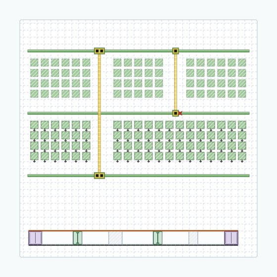
Here is what you are about to look at. Take the design that left the routing chapter. Zoom in until you can see individual wires on one metal layer. Now look at the space between the wires. In a normal routed block, most of that layer is empty. Chip finishing is the stage that fills a lot of that emptiness in, adds a second cut to vias that had one, moves some wires slightly further apart, closes every gap in every standard-cell row, and then proves the result can still be manufactured. It is the last implementation stage, and it is the first one whose customer is not another engineer. Its customer is a factory.
A beginner usually arrives here believing that routing was the last real step, and that finishing is cosmetic cleanup. That belief is comfortable and it is wrong. This chapter's job is to take it apart in Part 1, and then spend eleven more Parts proving it with measurements.
What this stage actually does
Concretely, by the end of this chapter you will be able to do eight things. You will confirm that a routed design is genuinely ready for finishing, rather than assuming the routing chapter's exit checklist is still true. You will choose the order in which finishing operations run, and explain why that order is not arbitrary. You will insert tap, boundary and filler cells, and say what each one physically provides. You will convert single-cut vias to redundant vias and read the conversion rate as a fraction rather than a verdict. You will reduce critical area with wire spreading and widening, and re-extract afterwards. You will measure metal density in windows, insert metal fill to correct it, and choose between fill types with reasons. You will measure what all of that did to timing, signal integrity and power, and repair what it broke. And you will run the signoff DRC loop and hand a manufacturable design to signoff with evidence attached.
As in every chapter of this guide, the goal is not memorizing flags. It is building the judgment a finishing engineer uses every day. Is this geometry manufacturable? What did making it manufacturable cost electrically? And is that cost affordable on this design, in this scenario, today?
| What enters this stage | What must leave it |
|---|---|
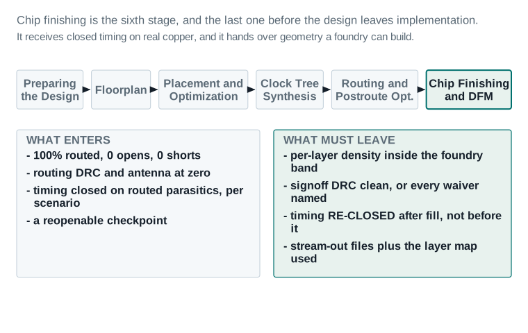
| A design routed to completion, with zero unrouted nets, zero opens and zero shorts (the Routing and Postroute Optimization exit gate). | Per-layer metal density inside the foundry's minimum and maximum band, measured in windows and not as a chip average. |
Routing design-rule violations and antenna violations at zero, verified with check_routes. | Signoff design-rule checking clean against the foundry runset, or every remaining item waived in writing with its rule name and reason. |
| Timing, transition, capacitance, crosstalk and power closed on routed parasitics, in every required scenario. | Timing, transition, capacitance and crosstalk re-closed on parasitics that were re-extracted with the finishing geometry in place. |
| A saved, reopenable checkpoint of the routed, postroute-optimized block. | Standard-cell rows continuous end to end, wells and substrate tied at the required interval, row ends capped. |
| A power and ground mesh that routing treated as fixed and did not disturb. | A saved checkpoint, plus the stream-out files and the exact layer map used to produce them. |
Why “the wires are done” is not the same as “the chip can be built”
Routing finished with a design that is electrically correct. Every net connects what it should connect, and nothing shorts to anything else. Every wire obeys the minimum width and minimum spacing rules the router was given. Timing closes. That is a real achievement, and the routing chapter earned it.
It is also not sufficient. A foundry does not only ask whether your shapes obey spacing rules one pair at a time. It asks statistical and process questions about the layout as a whole. How much metal is on this layer, in this hundred-micron square? Is that fraction inside the range my polishing process can handle? Are there via cuts with no redundancy, where a single manufacturing defect opens a net? Are there pairs of wires close enough that a particle of the size my fab actually produces would bridge them? Are there wells with no tie to a supply rail? None of these questions is about connectivity, and routing answers none of them.
That is the gap this chapter closes. Everything in it exists because a manufacturing process is physical, imperfect and statistical, and a layout that ignores those three facts yields badly even when it is logically perfect.
The five things finishing adds, and what each one costs
Chip finishing is not one operation. It is a sequence of them, and each one has a distinct purpose and a distinct price. The table below is the map of the whole chapter.
Read the "Taught in" column as an order, not a list. Tap, boundary and filler cells go in first because everything after them treats the row as a fixed, continuous surface. Redundant vias and critical-area reduction come next because they move geometry that has not yet been made dense with fill, which keeps the change cheap to re-extract. Metal fill comes after both, because filling around geometry that is about to move would just mean filling it twice. Signoff DRC comes last because it is the only step that checks the result of everything before it, not a step with an outcome of its own.
| Step | What it buys | What it costs | Taught in |
|---|---|---|---|
| Tap, boundary and filler cells | Wells and substrate tied to the rails, so the transistors cannot latch up; continuous diffusion across every row; protected row ends. | Area, and a small leakage increase. Changes the row content under every wire, so legality must be re-checked. | Part 5 |
| Redundant vias | A second cut in each via, so one manufacturing defect in a cut does not open the net. Lower via resistance as a side effect. | Enclosure area on both layers. Can block a neighbouring pin's access. Cannot always be inserted. | Part 6 |
| Critical-area reduction | Fewer places where a random particle of a given size causes a short or an open. Directly improves yield. | Moves geometry that extraction already characterised, so every moved net must be re-extracted and re-timed. | Part 6 |
| Metal fill | Local metal density inside the range the polishing process needs, on every layer, in every window. | Coupling capacitance on nets that were signed off as clean. This is the largest electrical cost in the chapter. | Part 7 |
| Signoff DRC and repair | Confidence that the real foundry rule deck, not the router's internal rules, finds nothing wrong. | Runtime, a tool licence, and repairs that can themselves create new violations. | Part 9 |
Read the middle column and the right column together. Every row buys something real. Every row charges for it. The whole discipline of this stage is refusing to accept the left-hand benefit without measuring the right-hand cost.
Where the manual actually covers this
One scoping fact matters more than any other in this chapter, and it catches people out. The ICC2 User Guide covers this subject across two chapters, not one. Chapter 7, “Chip Finishing and Design for Manufacturing”, covers tap cells, boundary cells, antenna, redundant vias, critical-area reduction, MIM capacitors and filler cells. Metal fill gets a single line there. The real treatment of metal fill is forty pages away, in Chapter 8, “IC Validator In-Design”, because metal fill in this tool is done by an external signoff engine.
If you learn metal fill from User Guide Chapter 7 alone, you will learn almost nothing about it. This chapter is planned against both, and Part 7 says so explicitly.
After this chapter, you will be able to
- Reopen a routed checkpoint and verify, rather than assume, that the routing exit state is still true.
- Explain why finishing operations run in a particular order, and what goes wrong when they do not.
- Insert tap, boundary and filler cells, and describe the physical thing each one provides.
- Convert vias to redundant vias, read the conversion rate correctly, and explain every non-conversion.
- Reduce critical area with wire spreading and widening, and re-extract the nets you moved.
- Measure metal density in windows, interpret a worst-window number, and correct it with fill.
- Choose between floating and tied fill, and between pattern-based and track-based fill, with reasons.
- Measure what finishing cost in timing, signal integrity and power, and repair what it broke.
- Run the signoff DRC loop against a foundry runset and triage its results into fix, ECO and waive.
- Work through a stage-exit checklist and decide, with evidence, whether a design is ready for signoff.
The physics you need before you run anything
Here is the orientation for this Part. Everything that follows is about one idea: a chip is not drawn, it is manufactured, and manufacturing is a physical process with tolerances. A drawn rectangle becomes a real piece of metal with a thickness that varies, edges that are not exactly where you put them, and a chance of a stray particle landing on it. Every concept in this Part is a consequence of that gap between the drawing and the thing.
Vocabulary
These terms are used throughout the chapter. Each one is defined again, in context, where it first does real work.
| Term | What it means |
|---|---|
| Design for manufacturing (DFM) | Changing a layout so it yields better, without changing what it does. Every DFM step in this chapter is functionally invisible and physically significant. |
| Yield | The fraction of manufactured die that work. DFM does not make a chip faster. It makes more of them work. |
| Metal density | The fraction of a given area, on a given layer, that is covered by metal. Always local, always measured in a window. |
| Density window | The square region inside which density is computed. The window slides across the layer in steps smaller than its own width, so windows overlap. |
| Density gradient | How much density changes between one window and the next. A steep gradient is its own violation, separate from the min and max. |
| CMP | Chemical-mechanical polishing. The process that flattens each layer after it is deposited. The reason density limits exist. |
| Dishing | The polished surface sinking below nominal over a region with too little metal. |
| Erosion | The polished surface sinking below nominal over a region with too much metal, because the surrounding dielectric wears away faster. |
| Metal fill | Dummy metal shapes added purely to raise local density. Carries no signal. |
| Floating fill | Fill shapes connected to nothing. Their voltage is whatever the surrounding geometry couples onto them. |
| Tied fill | Fill shapes connected to a supply net, usually ground. Their voltage is fixed. |
| Pattern-based fill | Fill placed by tiling a foundry-defined pattern into empty space, ignoring the routing track grid. |
| Track-based fill | Fill placed on routing tracks, at track width, so it looks like unused routing. |
| Redundant via | A via with more than one cut between the same pair of layers, so one defective cut does not open the net. |
| Via enclosure | The metal that must extend past the cut on each side, on both the lower and upper layer. |
| Critical area | The area in which the centre of a defect of a given size must land for it to cause a failure. |
| Wire spreading | Moving routed wires further apart where there is room, to shrink critical area. |
| Wire widening | Making routed wires wider where there is room, to shrink the critical area for opens and lower resistance. |
| Tap cell | A cell whose only job is to connect the n-well to VDD and the p-substrate to VSS. |
| Latch-up | A parasitic structure in CMOS switching on and shorting the supplies. What tap cells exist to prevent. |
| Boundary cell | A cell placed at the end of a row or against a block edge, so the diffusion and well structures terminate legally. |
| Filler cell | A cell with no function, placed to close gaps between real cells so the row's diffusion and wells stay continuous. |
| Antenna effect | Charge collected on a partly built wire damaging the gate oxide it is connected to, during manufacturing. |
| Protection diode | A small device added to a net to bleed collected charge away before it damages a gate. |
| Signoff DRC | Design-rule checking run with the foundry's own rule deck by a signoff engine, rather than with the router's internal rules. |
| Runset | The foundry-supplied file that defines the rules a signoff checker applies. Owned by the foundry, not by you. |
| PG augmentation | Adding extra power and ground metal after routing, into space that turned out to be free. |
| Layer map | The file that translates the tool's layer names into the foundry's GDSII layer numbers and datatypes. |
Metal density, and the misconception that ruins it
Metal density is the fraction of an area that is covered by metal on one layer. That definition is simple, and almost every beginner gets the next step wrong.
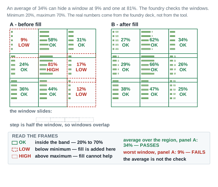
The mistake is to think of density as a property of the chip, or of a layer. It is not. Density is a property of a window: a square region, typically somewhere between fifty and a few hundred microns on a side, whose size the foundry specifies. The checker slides that window across the layer, in steps smaller than the window itself, and computes density at every position. A layer passes only if every window passes.
This matters enormously, because averages hide exactly the failures you care about. A layer can average a comfortable thirty-four percent while containing one window at nine percent and another at eighty-one percent. Both of those windows fail. The average passes. If you check the average, you ship the failure.
The window size itself is not something you choose. It comes from the foundry's density-check deck, tuned to the polishing hardware that specific fab runs, and it is one of the few finishing parameters that never appears as a tool default because no single default could be right across every process.
Two windows on the same layer can fail for opposite reasons, and the fix for one can be the cause of the other. A window failing the minimum needs metal added. A window failing the maximum needs metal kept out. Treat every failing window on its own terms; a single global fill pass tuned to the worst minimum can just as easily push a different window over its maximum.
Why density matters: chemical-mechanical polishing
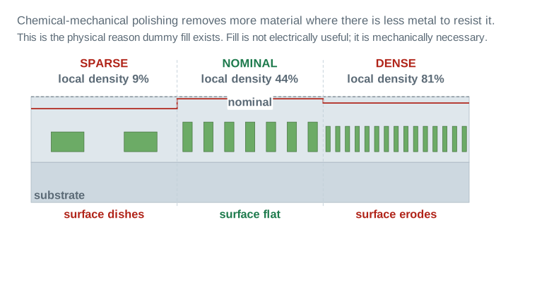
Each metal layer is built by depositing metal, then polishing it back flat so the next layer has a level surface to sit on. That polishing step is chemical-mechanical polishing, or CMP. It uses a rotating pad and an abrasive slurry, and it removes material at a rate that depends on what is underneath.
Where there is very little metal, the pad presses down into the softer dielectric between the sparse metal lines and cuts a shallow trough. That is dishing. Where there is a great deal of metal packed together, the dielectric between the lines wears away faster than the metal does, and the whole region sinks. That is erosion. Both leave the surface lower than nominal, and both leave it uneven.
An uneven surface is not a cosmetic problem. It has four consequences that reach all the way back to your timing report.
- Resistance is wrong. The metal left behind after over-polishing is thinner than the model assumed, so its resistance is higher than extraction predicted.
- The error accumulates. The next layer is deposited onto a dip, so its own thickness varies too. Each layer inherits the unevenness of the one below.
- Lithography loses focus. Patterning an uneven surface costs depth of focus, which shows up as width variation, not only height variation.
- At the extreme, the net opens. An over-polished dense region can be polished through entirely, and the die is simply dead.
Metal fill
Metal fill is the answer to sparse regions. It is dummy metal: shapes added to a layer purely to raise local density, carrying no signal and connected to no logic. The tool places it, the foundry's rules constrain it, and it is completely invisible to your netlist.
It is not invisible electrically. A fill shape sitting beside a signal wire forms a capacitor with it. That capacitance is added to a net that timing analysis already signed off. This is the chapter's central fact and Part 7 and Part 8 are built around it.
Floating fill and tied fill
Fill shapes are either left unconnected, which is called floating fill, or connected to a supply net, usually ground, which is called tied or grounded fill. This is the most important fill decision a beginner meets, and the difference is not subtle.
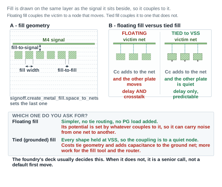
A floating fill shape has no defined voltage. Whatever couples to it sets its potential, so it moves when its neighbours move. That makes it a path between two signal nets: net A couples charge onto the fill shape, the fill shape couples it onward to net B. The result is extra delay and extra crosstalk.
A tied fill shape is held at ground. It still adds capacitance to a nearby net, so the net still gets slower. But the other plate of that capacitor does not move, so the added load is predictable and it carries no noise between nets. Extraction handles it cleanly.
Tied fill therefore behaves better and costs more: it needs tie geometry, it loads the ground net, and it is more work for the fill tool and the router. Usually the foundry's deck settles the question. When it does not, that decision belongs with a senior engineer, not a default first move.
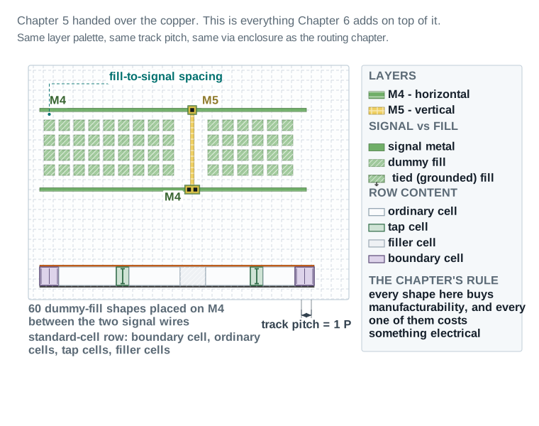
The fill-to-signal spacing dimensioned just below is not a fixed number picked once and forgotten. It is set through signoff.create_metal_fill.space_to_nets, the application option Part 7 walks through step by step, and it is the single value that trades fill density against coupling risk on every layer it touches. Widen it and coupling drops but so does density, which can push a marginal window below its minimum; narrow it and the reverse happens. Part 7 also covers the paired choice this section only names, floating versus tied, with the actual Nimbus-8 tie decision recorded per layer.
Both settings apply per layer, not once for the whole stack, because the trade lands differently on each one. A layer carrying mostly wide power straps can tolerate tighter fill-to-signal spacing than a layer carrying fine-pitch clock or data routing, where the same spacing buys much less density for much more coupling risk. Reading the figure below correctly means reading it as one layer's answer to that trade, not the whole stack's.
Redundant vias
A via is the connection between two metal layers. It is made by etching a hole, called a cut, through the dielectric and filling it with metal. A cut is small, and the etch that makes it is one of the least reliable steps in the process. A cut that does not open properly, or that fills badly, is an open circuit.
A redundant via is a via with more than one cut doing the same job. If one cut fails, the other still carries the net. This is one of the cheapest yield improvements available, and it also lowers via resistance, which helps timing slightly.
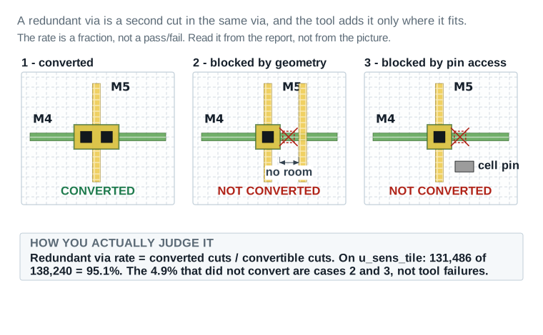
It cannot always be done. Each cut needs metal extending past it on every side, on both layers, and that metal is the enclosure. A second cut needs a wider enclosure, and the wider enclosure needs room. Two situations commonly deny it. A neighbouring wire may sit too close for the wider enclosure to fit without violating spacing. Or the via may land on a cell pin, where the extra enclosure would block the only track by which a router can reach that pin.
Insertion is not uniform across a design. Clock nets and wide power straps tend to convert at close to one hundred percent, because they route on wide tracks with room to spare. The residual failures cluster on dense signal routing in the most congested regions, which is also where a defect would do the most damage. The conversion a design actually achieves matters more than its layer average suggests, so a via-mapping report broken out by net class is worth reading before accepting a single chip-wide number.
The via-mapping table itself is worth reading, not just its summary rate. It records, cut by cut, which vias converted, which were attempted and blocked, and which were never attempted because the tool's spacing check ruled them out before trying — three different outcomes a single percentage collapses into one number. A design with a high conversion rate built mostly from clock and power vias can still leave its most defect-sensitive signal nets single-cut, and the mapping table is the only place that distinction is visible.
Critical area and random defects
Manufacturing produces stray particles. A particle that lands on a layer can bridge two wires and cause a short, or sit in a wire and cause an open. Whether it does damage depends entirely on where it lands and how big it is.
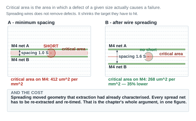
Critical area is the area in which the centre of a particle of a given size must land for it to cause a failure. That is the whole definition. If two wires are far apart, only a very large particle can bridge them, and the region in which its centre must land is narrow. Move the wires closer and the same particle bridges them from a wider range of positions, so the critical area grows.
This is why critical area, rather than raw spacing, is the quantity the tool optimises. It converts a geometric fact into a yield number. Reducing it by thirty-five percent means roughly thirty-five percent fewer shorts from particles of that size.
Tap cells, boundary cells and filler cells
Everything above this point has been about metal. This last group is about the silicon underneath it.
A CMOS standard cell sits in a well, and the well and the substrate around it must be held at a known voltage. If they are not, a parasitic structure inside the silicon can switch on and short VDD directly to VSS. That is latch-up, and it destroys the chip. A tap cell contains nothing but the connection that prevents it: the n-well tied up to VDD and the p-substrate tied down to VSS. The technology specifies a maximum distance any point may be from a tap, and finishing inserts taps at or below that interval.
A filler cell contains no function either. Its job is continuity. Standard cells have diffusion and well structures that must not simply stop at a cell edge with nothing beside them, so the gaps between placed cells are closed with filler cells of assorted widths until the row is continuous end to end.
A boundary cell, sometimes called an end-cap, does the same job at the places where a row genuinely ends: the left and right ends of each row, and anywhere the row meets a block edge, a macro or a voltage-area boundary. Those edges need a defined termination, not just filler.
None of the three carries logic, so none of them shows up in a timing report, and that is exactly why they are easy to under-budget for. On a real block the technology's maximum tap-to-tap distance sets a hard upper bound on spacing, but the actual placed interval usually comes in well under it, because filler and boundary insertion follow the row geometry the placer already committed to, not a clean grid drawn from scratch. The cost is area and a small leakage increase, paid once, before anything electrical in this chapter starts.
Order matters here for a reason that has nothing to do with any of the three cells themselves. Every later step in this chapter — redundant vias, critical-area reduction, fill — treats the standard-cell row as fixed background it routes and fills around. Insert taps, boundary and filler cells after those steps instead of before, and each one has to be re-checked against geometry that may already have moved, for no benefit: none of them interact electrically with metal density or via conversion at all. Row finishing goes first because it is the one group of operations every later step can safely assume is already done.
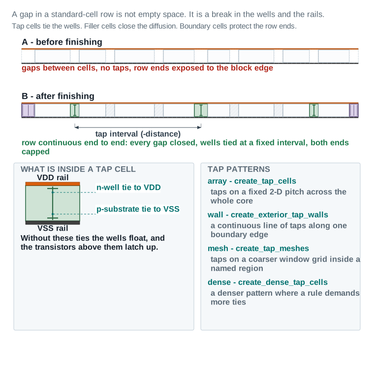
-distance argument. The enlarged panel at the lower left shows what is inside a tap cell: a vertical tie running between the orange VDD rail and the dark VSS rail, with leader lines labelling the n-well tie to VDD and the p-substrate tie to VSS. The panel at the lower right lists the four tap patterns and the command that creates each one.Antenna, one more time
The routing chapter introduced the antenna effect and fixed most of it. It appears again here for a specific reason, so the distinction is worth stating plainly.
During manufacturing, a wire is built before the layers above it exist. While it is partly built, it can act as a collector: charge accumulates on it from the plasma used in processing. If that wire is connected to a transistor gate and to nothing else that can bleed the charge away, the charge can punch through the thin gate oxide and damage the device permanently.
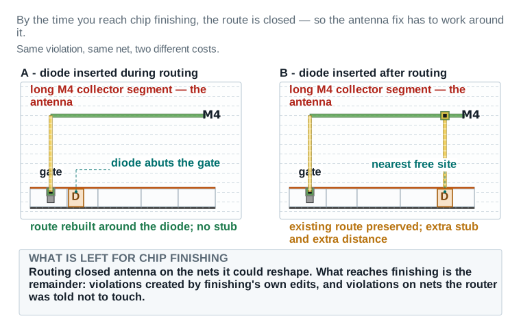
Routing fixed antenna violations while it still had freedom to reshape nets. What reaches chip finishing is the remainder: violations that finishing's own edits created, and violations on nets the router was told not to touch. Fixing them now is harder, because the route is closed and must be preserved. Part 5 covers it.
Signoff DRC, and why the router's DRC was not enough
The router checks its own geometry against its own internal rule model as it works. That model is fast and it is deliberately simplified, because the router has to consult it millions of times.
Signoff DRC is different in kind. It runs the foundry's actual rule deck, called a runset, through a dedicated verification engine. The deck contains rules the router's model does not carry at all: density rules, complex multi-layer conditional rules, antenna rules in their full form, double-patterning colouring rules, and rules that depend on the shape of a region rather than on a pair of edges.
Verifying what routing actually handed you
Here is the orientation for this Part. Imagine taking delivery of a house from a builder. You have their sign-off sheet saying the roof is sound and the wiring is tested. Before you start knocking walls about, you go and look at the roof yourself. This Part is that walk-round. You reopen the routed checkpoint, re-measure every promise the routing chapter made, and find the one thing nobody measured at all.
How commands are shown in this chapter
Reopening the routing checkpoint
The routing chapter's exit state was saved as a named block. Chip finishing begins by opening it and confirming it opens cleanly.
Reopen the routed, postroute-optimized block
open_block nimbus8_sens_tile_routed_postopt_v1
report_design -routing
check_routes -open_net true -drc true -antenna true
What you are checking: that the block opens with no unexplained warning, that the routing summary still reads one hundred percent routed, and that the three connectivity and rule checks still return zero. If any of these disagrees with the routing chapter's exit record, stop. Something changed between then and now, and finding out what matters more than starting finishing on time.
The fourteen readiness gates
The board below is the readiness check in full. The first ten gates re-verify what routing claimed. The last four are about what routing never looked at, and they are the reason this Part exists.
Chapter 5 closed with a stage-exit checklist and a saved checkpoint. This board does not take that on trust. It reopens the checkpoint and re-measures every promise, because the thing you inherit is the thing you are about to spend the whole chapter changing.
| Item | Evidence | Source command / report | Threshold | Status | Required action |
|---|---|---|---|---|---|
| Connectivity and geometry inherited from routing | |||||
| 1. Route completion | 100% routed, 0 unrouted nets | report_ | 100%, 0 unrouted | PASS | — |
| 2. Opens and shorts | 0 opens / 0 shorts | check_ | 0 / 0 | PASS | — |
| 3. Routing DRC | 0 violations (248 after route_, cleared in 3 search-and-repair iterations) | check_ | 0, or every item dispositioned | PASS | — |
| 4. Antenna | 0 violations (37 initially: 28 fixed with diodes, 9 with layer jumpers) | check_ | 0, or every item dispositioned | PASS | — |
| 5. Congestion overflow | 0% H / 0% V | global-route overflow report | 0% after detail routing | PASS | — |
| Item | Evidence | Source command / report | Threshold | Status | Required action |
|---|---|---|---|---|---|
| Timing and power inherited from postroute optimization | |||||
6. Setup timing, func_ | WNS +0.011 ns, TNS 0 ns | report_ / report_ | WNS ≥ 0, TNS = 0 | PASS | — |
7. Setup timing, test_ | WNS +0.015 ns | report_ | WNS ≥ 0 | PASS | — |
8. Hold timing, func_ | WNS +0.019 ns, TNS 0 ns | report_ | WNS ≥ 0, TNS = 0 | PASS | — |
| 9. Transition, capacitance, crosstalk | max transition 0 / max capacitance 0 / crosstalk delay 0 / noise 0 violators | report_ | 0 in every category | PASS | — |
| 10. Power baseline recorded | dynamic 1.87 mW, leakage 0.097 mW, clock share 0.41 mW | report_ | A saved baseline exists to measure against | PASS | — |
| What routing did NOT measure — the real entry risk | |||||
| 11. Per-layer metal density | Never measured. Routing has no density check and does not report one. | none — this is the gap | Every layer inside the foundry min/max band | REVIEW | Measure before changing anything, in Part 7, with signoff_. Treat the first measurement as the baseline, not as a result. |
| 12. Redundant via coverage | 100% on flagged nets only; the other 138,240 vias were never considered | routing-stage redundant-via note | Stated, and understood to be partial | PASS | — |
| 13. Filler, tap and boundary cells | None inserted. Rows contain real gaps. | check_: 0 violations, but gaps are legal | Known empty at entry | PASS | — |
| 14. Checkpoint reopens cleanly | nimbus8_ reopened, 0 unexplained warnings | open_ then report_ | Opens with no unexplained message | PASS | — |
Readiness verdict for u_sens_tile reopened from nimbus8_sens_tile_routed_postopt_v1: 13 PASS, 1 REVIEW, 0 BLOCKER → GO to chip finishing.
Read it: Read the Evidence column against the Threshold column, and only then look at Status. Gate 11 is the one that matters most and it is deliberately a REVIEW, not a PASS: routing measured density nowhere, so the number you are about to spend this chapter fixing has never actually been checked. A gate that has never been measured is not a passing gate.
Field values in the Evidence column are this chapter's illustrative teaching data, not a real tool transcript.
The gate that matters most
Gate eleven is deliberately classified REVIEW rather than PASS, and it is worth dwelling on why. Routing has no density check. It does not compute metal density, it does not report it, and it has no opinion about it. So the number that this chapter exists to fix has never been measured on this design.
A gate that has never been measured is not a passing gate. Classifying it PASS because nothing has complained would be exactly the habit this guide is written against. The required action is to measure it first, before changing anything, and to treat that first measurement as a baseline rather than as a result.
What you must have before you start
Beyond the design itself, finishing needs inputs that come from outside the tool. Not having them is the single most common reason a finishing run stalls on day one.
| Input | Where it comes from | What happens without it |
|---|---|---|
| Tap cell, filler cell and boundary cell library cells | The standard-cell library vendor, in the reference libraries. | No row finishing is possible at all. Nothing to insert. |
| The maximum well-tie distance | The technology file or the library documentation. | Taps get inserted at a guessed interval, which is either wasteful or unsafe. |
| The foundry DRC runset | The foundry, through your process design kit. | Signoff DRC cannot run. The router's internal DRC is all you have. |
| The foundry fill runset and density limits | The foundry, usually as a separate deck from the DRC runset. | Fill cannot be inserted correctly. Every parameter would be a guess. |
| An IC Validator installation and licence | Your CAD or IT group. | Every signoff and fill command in Part 7 and Part 9 is unavailable. |
| The GDSII layer map | The foundry, or your own methodology group. | Stream-out produces a file that opens cleanly and is wrong. |
| Saved baseline reports | The routing chapter's exit. | You cannot measure what finishing cost, because you have nothing to subtract from. |
Save a recovery point before you change anything
Finishing is destructive in a specific sense. It adds thousands of cells and hundreds of thousands of shapes, and undoing that selectively is far harder than reopening a checkpoint. Save one now.
Save the pre-finishing recovery point
save_block -as nimbus8_sens_tile_pre_finish_v1Why this specific name: it states the design, the partition, the stage boundary and a version. Six weeks later, when someone asks which block was the last one before fill, the name answers without anyone opening it.
Gate — ready to begin chip finishing
- WHY IT MATTERS
- Everything downstream is measured as a change from this state. If this state is not what you think it is, every delta you compute is wrong.
- WHAT TO CHECK
- The routed checkpoint reopens cleanly; route completion, opens, shorts, DRC and antenna are all as the routing exit recorded them; timing and power baselines exist on disk; density has been recognised as unmeasured; the foundry runsets and the layer map are in hand; a pre-finishing checkpoint is saved.
- EVIDENCE OF A HEALTHY RESULT
- Dashboard 1 reads 13 PASS, 1 REVIEW with a stated action, 0 BLOCKER, and the REVIEW is gate 11.
- CONSEQUENCE IF WRONG
- If you start from a block that is not the one you think it is, the electrical impact board in Part 8 compares the wrong two states, and it will look reassuring while being meaningless.
- SAFE RECOVERY
- Reopen
nimbus8_sens_tile_routed_postopt_v1and re-run the three checks. If they still disagree with the routing exit record, the routing chapter's own recovery point,nimbus8_sens_tile_pre_route_v1, is still available and routing can be re-run rather than guessed at.
Why the sequence is not arbitrary
Here is the orientation for this Part. Think about decorating a room. You plaster before you paint, and you paint before you lay the carpet, because each step makes a mess of the one before it if you get the order wrong. Chip finishing has exactly that structure. Several of its steps modify geometry that other steps depend on, so running them in the wrong order means running some of them twice, or shipping a design where an earlier step's result was silently undone.
The order this chapter uses
| # | Step | Why it sits here | Part |
|---|---|---|---|
| 1 | Re-verify the routed state; save a recovery point | Everything later is measured as a change from this. It has to be known. | 3 |
| 2 | Insert tap cells | Taps are placed cells and need row space. They go in before fillers claim it. | 5 |
| 3 | Insert boundary cells | Boundary cells define where rows legally end, which constrains where fillers may go. | 5 |
| 4 | Reduce critical area: wire spreading and widening | Moves and resizes metal. Must precede any density measurement, and precede fill. | 6 |
| 5 | Insert redundant vias | Changes via enclosure geometry, which changes local density. Also before fill. | 6 |
| 6 | Fix any remaining antenna violations | Steps 4 and 5 can create new ones. Doing this earlier means doing it twice. | 5 |
| 7 | Insert filler cells | Fillers close whatever gaps remain once every other cell is placed. | 5 |
| 8 | Measure metal density — the baseline | All metal-moving steps are now done, so this number is stable. | 7 |
| 9 | Augment the power and ground mesh | PG augmentation adds metal and therefore density. It goes in before fill, so fill sees it. | 9 |
| 10 | Insert metal fill | Fill is last among the metal-adding steps, because it fills what is left. | 7 |
| 11 | Re-extract parasitics and re-close timing | Fill changed the parasitics. Nothing signed off before this point is still valid. | 8 |
| 12 | Run signoff DRC and repair | Checks everything above it, including the repairs made in step 11. | 9 |
| 13 | Re-measure density; save; stream out | Repairs in step 12 can remove fill. The final density number comes after them. | 12 |
The four orderings that go wrong
Rather than memorising the table, learn the four mistakes it prevents. Each one is common, and each one is recoverable but expensive.
Fill before critical-area reduction
What happens. Fill is placed into the space between wires. Wire spreading then tries to move those wires further apart, and the space is occupied. Either the spreading achieves much less than it should, or the tool removes fill to make room and the density you just achieved falls back.
Symptom. Critical-area reduction reports a much smaller improvement than the same design achieved in an earlier run, for no obvious reason.
Fix. Remove the fill, spread, then re-fill. Spreading before filling avoids the whole loop.
Filler cells before tap cells
What happens. Filler insertion closes every gap in every row. Tap insertion then needs row space at a fixed interval, and finds it fully occupied by fillers. The tool must remove fillers to place taps, and the taps end up wherever a filler happened to be, rather than where the tie distance requires.
Symptom. Taps at an irregular interval, and a well-tie distance check that fails in places despite taps having been inserted.
Fix. Taps first, boundary cells second, fillers last. Fillers are the step that consumes leftovers, so it goes last by definition.
Timing signoff before fill
What happens. Parasitics are extracted, timing closes, everyone is pleased, and then fill is inserted. Fill adds coupling capacitance to every net it sits near, and nobody re-extracts. The design ships with a timing report describing a design that no longer exists.
Symptom. None, locally. That is exactly what makes it dangerous. It shows up at signoff, or at silicon.
Fix. Extraction and timing closure come after fill, always. Part 8 is placed where it is for this reason.
Density measured before PG augmentation
What happens. Density is measured, fill is sized to correct it, and then PG augmentation adds substantial extra metal into the same layers. Local density overshoots, and some windows now exceed the maximum.
Symptom. Windows failing the density maximum after a run that was supposed to fix a minimum problem.
Fix. Augment first, then measure, then fill. Any metal-adding step belongs before the measurement that sizes the fill.
The flagship view: one region, six steps
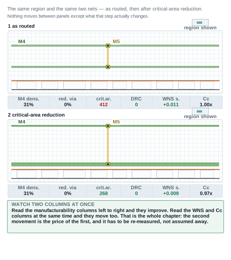
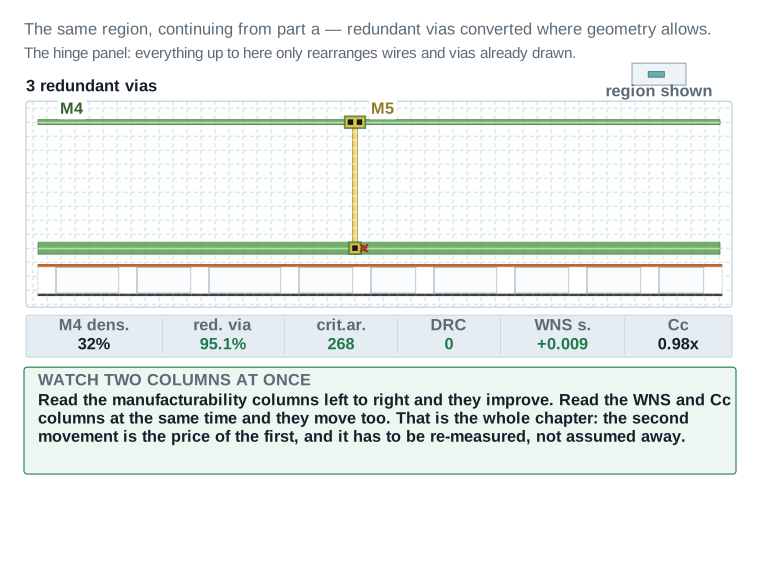
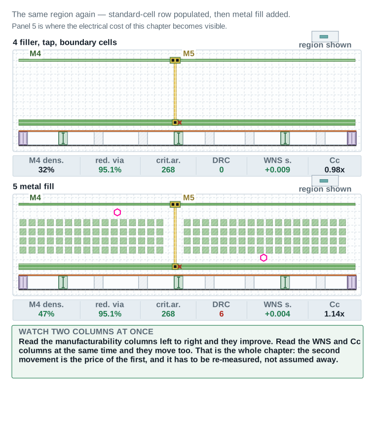
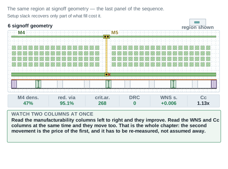
The two figures below are the most useful thing in this chapter. They show a single physical region — the same two nets, the same via positions, the same standard-cell row, at fixed coordinates — carried through all six finishing steps. Nothing moves between panels except what that step actually changes.
Each panel carries a status strip with six numbers: metal density on M4, the redundant via rate, critical area, the DRC count, setup slack in the worst-case corner, and total coupling capacitance relative to where it started. Read the first four as they improve. Read the last two at the same time.
| Field | What it reports | Which way improvement runs |
|---|---|---|
| M4 density | Metal density on the layer being filled, as a percentage. | Up, toward the band, until fill is inserted. |
| Redundant via rate | Double-cut vias as a fraction of every via site eligible for one. | Up, toward 100 percent. |
| Critical area | The random-defect exposure metric introduced in Part 2. | Down. |
| DRC count | Open violations against the runset active at that step. | Down, to zero by panel 6. |
| Setup slack | Worst-case setup slack in func_ss_0p72v_125c. | Watched, not chased. It is allowed to fall. |
| Coupling capacitance | Total coupling on the two tracked nets, relative to panel 1. | Watched. A rise here is the cost the chapter is about. |
The six steps run across four figures rather than one, because six panels at a size where the status strip stays legible do not fit on a single page, or even on two. Figures 9a and 9b, immediately below, carry the first three steps between them: 9a shows the region as routed and after critical-area reduction; 9b shows the redundant-via conversion that follows. Figures 9c and 9d, right after, carry the last three: 9c shows the row populated with boundary, tap and filler cells and then metal fill added; 9d shows the signoff geometry that results. Read all four figures as one continuous sequence, not as separate comparisons — panel 6, in 9d, is the same physical region and the same two nets as panel 1, in 9a, six steps later, and the status strip is what lets you confirm that nothing else about the region changed along the way.
Reading the last two fields at the same time, rather than one after the other, is the point of the whole exercise. Setup slack and coupling capacitance do not move together by coincidence: every panel where coupling rises is a panel where the fill tool or the router added something near the tracked nets, and setup slack is what pays for it. Across all six panels the region's setup slack falls from an as-routed +0.011 nanoseconds to a final +0.006, a drop of five picoseconds, and every picosecond of that drop lines up with a step that also moved the coupling number. Read the manufacturability columns for whether the region is ready to ship. Read the last two together for what shipping it cost.
Keep the units straight while you read: critical area, DRC count and the two rate fields are absolute or normalised counts, while setup slack is a time and coupling capacitance is a ratio to panel 1's own starting value, not an absolute farad number. That is deliberate. The chapter's argument is about the shape of the cost, not this one region's specific capacitance in femtofarads, and a relative number keeps the comparison honest across any region you check it against.
What runs once, and what runs in a loop
Most of the order above runs once. Two parts of it do not, and recognising which is which saves a lot of confusion.
- Steps 2 to 10 run once on a healthy design. If you find yourself running fill three times, something upstream is wrong and repeating the step will not fix it.
- Step 11, extract and re-close timing, loops with its own repairs. Repairing a transition violation changes parasitics, which requires another measurement. Part 8 treats this as a measured loop with an exit condition.
- Step 12, signoff DRC, always loops. A repair can create a new violation, so every fix goes back through the check rather than to the exit. Part 9 draws this explicitly.
Gate — the order is settled before the first insertion
- WHY IT MATTERS
- Order mistakes are not detected by any checker. Every step passes its own check while silently undoing an earlier one.
- WHAT TO CHECK
- That metal-moving steps precede the density baseline; that cell-adding steps run taps, then boundary cells, then fillers; that every metal-adding step precedes fill; and that extraction and timing closure follow fill rather than precede it.
- EVIDENCE OF A HEALTHY RESULT
- A written run order, with each step's position justified by its dependency, before the first command runs.
- CONSEQUENCE IF WRONG
- At best, steps run twice and the schedule slips. At worst, timing is signed off against pre-fill parasitics and the error reaches silicon.
- SAFE RECOVERY
- Reopen
nimbus8_sens_tile_pre_finish_v1and run the sequence in the correct order. This is precisely why that checkpoint was saved in Part 3.
Finishing the silicon, not the metal
Here is the orientation for this Part. Everything so far has been about wires. Now look underneath them, at the rows of standard cells. After placement and routing, those rows are not solid. They have gaps, they have open ends, and the wells under them have no guaranteed connection to a supply. This Part closes all three, with three kinds of cell that between them contain no logic whatsoever.
Tap cells
A tap cell ties the n-well to VDD and the p-substrate to VSS. That is all it does. It contains no transistors that do anything useful.
Without it, the wells float. A floating well lets a parasitic bipolar structure inside the CMOS silicon switch on, and once it does it shorts VDD to VSS through a path that will not turn off until power is removed. That is latch-up, and it usually destroys the device. The technology specifies a maximum distance from any point in the design to the nearest tap, and that distance is not advisory.
Insert tap cells on a fixed two-dimensional pitch
create_tap_cells \
    -lib_cell nimbus8_lib/TAPCELL_X1 \
    -distance 18.0 \
    -pattern every_row \
    -skip_fixed_cells \
    -prefix TAP_
Reading the arguments: -lib_cell names the tap cell from the reference library. -distance is the tap interval in microns and must come from the technology, not from habit. -pattern selects every_row, every_other_row or stagger; staggering taps between adjacent rows can reach the same tie distance with fewer cells. -skip_fixed_cells leaves anything already marked fixed alone. -prefix makes every inserted cell identifiable later by name, which matters enormously when something has to be removed selectively.
Command verification: see Part 3. create_tap_cells is verified.
The four tap patterns
A uniform array is the common case, but three other shapes exist and each solves a different problem.
| Pattern | Command | When you use it |
|---|---|---|
| Array | create_tap_cells | The default. Taps on a fixed two-dimensional pitch across the whole core or a named voltage area. |
| Generic cell array | create_cell_array | Placing any repeating cell on a pitch, with explicit x and y increments, offsets, orientation and an optional checkerboard. Used where a tap array needs finer control than create_tap_cells exposes. |
| Exterior tap wall | create_exterior_tap_walls | A continuous line of taps just outside a boundary edge, on a named side. Used around voltage areas and macro edges. |
| Interior tap wall | create_interior_tap_walls | The same idea inside a boundary edge of the core area, at a chosen horizontal spacing. |
| Tap mesh | create_tap_meshes | Taps placed on a coarser window grid inside a specified bounding box, described by a mesh window specification. |
| Dense taps | create_dense_tap_cells | A denser pattern than the main array, for a region whose rule demands more ties than the general case. |
Boundary cells
A standard-cell row cannot simply stop. The diffusion and well structures inside the cells at the row's end need a defined termination, and so do the cells that sit against a macro, a block edge or a voltage-area boundary. Boundary cells, also called end-cap cells, provide it.
In ICC2 the rules come first and the insertion follows. You declare which library cell belongs at each kind of edge, and then run the insertion.
Declare the boundary cell rules, then insert and check
set_boundary_cell_rules \
    -left_boundary_cell nimbus8_lib/ENDCAPL_X1 \
    -right_boundary_cell nimbus8_lib/ENDCAPR_X1 \
    -top_boundary_cells nimbus8_lib/ENDCAPT_X1 \
    -bottom_boundary_cells nimbus8_lib/ENDCAPB_X1

compile_targeted_boundary_cells -all_targets

check_boundary_cells
What each does: set_boundary_cell_rules records which cell goes at which kind of edge; it inserts nothing by itself. compile_targeted_boundary_cells creates and places the cells around the target objects, and -all_targets applies it to every eligible object rather than a named list. check_boundary_cells verifies the result and must return zero violations. Use report_boundary_cell_rules to read back what is currently set, which is worth doing before insertion rather than after.
Command verification: see Part 3. All four commands are verified, as are create_targeted_boundary_cells, check_targeted_boundary_cells and remove_boundary_cell_rules.
Filler cells
Filler cells close what is left. Once taps and boundary cells are placed, every remaining gap between cells in every row is filled with function-free cells of assorted widths until the row is continuous.
Fillers go last among the cell-insertion steps for a simple reason: they consume whatever space is left, so anything that needs space must have taken it already.
Insert standard-cell fillers
create_stdcell_fillers \
    -lib_cells { nimbus8_lib/FILL_X8 nimbus8_lib/FILL_X4 \
                 nimbus8_lib/FILL_X2 nimbus8_lib/FILL_X1 } \
    -prefix FILL_

check_legality -chipfinishing auto
Why the widths are listed largest first: the tool places the widest cell that fits, then the next, and so on down to the single-site filler. Listing them in descending order gives the fewest cells for the same coverage, which keeps the database smaller and the row easier to read. check_legality with -chipfinishing auto applies the legality checks appropriate to a finished design rather than to a freshly placed one.
Command verification: see Part 3. Both commands are verified, as are create_left_right_filler_cells, create_vtcell_fillers, set_vt_filler_rule, remove_stdcell_fillers_with_violation, remove_fill_cells and get_fill_cells.
When fillers themselves cause DRC violations
A filler cell is a real piece of silicon with real geometry, and occasionally the filler that fits a gap dimensionally creates a design-rule violation against its neighbours. The tool provides a specific remedy rather than making you find them by hand.
Remove and replace fillers that violate design rules
remove_stdcell_fillers_with_violation \
    -check_only true

remove_stdcell_fillers_with_violation \
    -shorts_only true

create_stdcell_fillers \
    -lib_cells { nimbus8_lib/FILL_X2 nimbus8_lib/FILL_X1 } \
    -prefix FILLR_
The pattern: run once with -check_only true to see what would be removed without removing it, then run for real, then re-fill the vacated gaps with narrower cells. The second insertion uses a different prefix so the replacements stay identifiable.
Threshold-voltage-aware fillers
Some libraries require that the filler beside a cell match that cell's threshold-voltage flavour, because the implant regions must stay coherent. Where that applies, the rule is declared first and a different insertion command is used.
set_vt_filler_rule associates a set of filler cells with the threshold-voltage types they may abut, and create_vtcell_fillers then inserts fillers according to the threshold-voltage types of the neighbouring cells. Both are verified commands. Whether your library needs them is a library question, not a tool question, so check the library documentation before assuming either way.
Recall Figure 7: the row before and after finishing, with boundary cells at both ends, tap cells at a fixed interval and every gap closed by a filler cell — that is exactly the layout this Part just built, one operation at a time.
Antenna violations that survive into finishing
Routing closed the antenna violations it could. Two categories reach this stage anyway.
The first is violations that finishing itself created. Wire spreading and widening in Part 6 change the area of metal attached to a gate, and a net that was comfortably inside its antenna ratio can cross it after being widened. The second is violations on nets the router was told not to touch, where the fix had to be deferred.
The difference from routing is freedom. During detail routing, the router could reshape the net and place a diode wherever it liked, rebuilding the route around it. After detail routing, the route is closed and must be preserved, so the diode goes into the nearest free site and a stub connects it. That is cheaper to compute and worse for area and for timing.
On u_sens_tile, this is not a hypothetical count. Wire spreading and widening in Part 6 created 41 new antenna violations, all of them the first category above — nets whose widened or spread collector segment pushed the metal area on some gate past its ratio limit. None were carried over from routing, because routing's own antenna check ran clean before this chapter's handoff; the finishing chapter's edits are the entire cause. Every one of the 41 was fixed with a diode inserted after the fact, at the higher area-and-timing cost described above, because by the time critical-area reduction ran, the route the diode has to preserve was already closed.
This is also why the order in Part 4 puts antenna repair after critical-area reduction and redundant-via insertion rather than before them: those two steps are what creates most of the violations finishing itself is responsible for, so repairing antenna earlier would just mean repairing it again after they run.
The stub itself is not free. A diode placed at the nearest free site, rather than built into the net's own reshaped route, is reached by a short additional wire the router never planned for, and that wire adds both resistance and a small parasitic load the original timing closure never saw. On a net that was already close to its slack budget, forty-one of these stubs is forty-one small, avoidable timing costs stacked on top of the finishing chapter's own headline changes — which is one more reason the ordering in this Part exists: fewer violations reaching this stage means fewer stubs paying that price.
Insert protection diodes for named violations
check_routes -antenna true

create_diodes -options $antenna_violation_list
Reading it: check_routes -antenna true reports the violations. create_diodes takes a list of violations to fix rather than a mode setting, so you choose what to repair rather than repairing everything. The antenna rules themselves are declared with define_antenna_rule for a whole mode, and define_antenna_layer_rule for one layer, both of which take the metal, cut and diode ratios that the technology specifies.
Command verification: see Part 3. check_routes, create_diodes, define_antenna_rule, define_antenna_layer_rule and derive_hier_antenna_property are verified.
Gate — row finishing complete
- WHY IT MATTERS
- Missing taps cause latch-up, which destroys the part. Gaps in rows break diffusion and well continuity. Neither failure is visible in a timing report.
- WHAT TO CHECK
- Tap interval at or below the technology maximum;
check_boundary_cellsat zero violations; every row continuous end to end;check_legality -chipfinishing autoat zero violations; no filler-induced DRC violations remaining; antenna at zero after any diodes inserted. - EVIDENCE OF A HEALTHY RESULT
- Zero from
check_boundary_cells, zero fromcheck_legality, zero antenna violations fromcheck_routes -antenna true, and a tap count consistent with the core area divided by the tap pitch. - CONSEQUENCE IF WRONG
- A well-tie distance violation is a latch-up risk that no later stage will catch. A gap in a row is a signoff DRC violation at best, and a fab-level structural error at worst.
- SAFE RECOVERY
- Every insertion in this Part used a prefix, so every inserted cell can be selected by name and removed with
remove_cells, and the step re-run with corrected arguments. If that becomes tangled, reopennimbus8_sens_tile_pre_finish_v1.
Buying yield with geometry
Here is the orientation for this Part. Both steps in it do the same thing in different ways: they make the layout more tolerant of manufacturing defects that have not happened yet. Nothing here fixes a bug. Everything here raises the fraction of manufactured die that come out working. Picture it as insurance bought with area and with a little timing margin.
Redundant vias
Via cuts are among the least reliable structures in the process. Adding a second cut in parallel means a single defective cut no longer opens the net. Via resistance drops as a bonus, which helps timing very slightly.
The insertion is a single command with an effort level, but the interesting part is what it does not convert.
Convert single-cut vias to redundant vias
add_redundant_vias \
    -effort high \
    -timing_preserve_setup_slack_threshold 0.020 \
    -timing_preserve_hold_slack_threshold 0.020

report_via_mapping
Reading the arguments: -effort takes low, medium or high and trades runtime for conversion rate. The two -timing_preserve thresholds are the important pair: they tell the tool to leave alone any via on a net whose slack is inside the given margin, so insertion cannot spend the last twenty picoseconds of a critical path. -nets restricts the whole operation to a named collection, and -list_only true reports what would be done without doing it.
Command verification: see Part 3. add_redundant_vias, report_via_mapping, add_via_mapping, remove_via_mappings and create_via_def are verified.
The via mapping table
Conversion is driven by a mapping table: for each single-cut via definition, which multi-cut definitions may replace it. The tool ships a default table derived from the technology, and you can add your own entries.
add_via_mapping declares a mapping with -from naming the via pattern to replace and -to naming the acceptable destination vias, with an optional -weight to prefer one over another and a -transform argument controlling whether flipped or rotated forms are allowed. report_via_mapping prints the table currently in effect, and remove_via_mappings deletes entries. Reading the table before insertion is worth the minute it takes, because a conversion rate that looks disappointing is often a mapping table that has no entry for the via type your design actually uses.
Reading the rate correctly
The redundant via rate is a fraction: converted cuts divided by convertible cuts. It is not a pass or fail verdict, and it will not reach one hundred percent on any real design.
On the Nimbus-8 sensor tile, 131,486 of 138,240 cuts converted, which is 95.1 percent. The 6,754 that did not convert break down into 4,102 blocked by adjacent geometry and 2,652 blocked by pin access. Those are geometric facts about a crowded layout, not tool failures.
Recall Figure 5: redundant via rate on u_sens_tile, 131,486 of 138,240 = 95.1%. The 4.9% that did not convert are cases 2 and 3 — blocked by geometry and by pin access — not tool failures.
Isolated vias
A separate command targets vias that remain single after the main pass. signoff_fix_isolated_via identifies isolated vias and inserts redundancy where it can, and it can also update track fill at the same time. It runs through the signoff engine, so it is Environment-specific: it requires IC Validator and a foundry runset, and what it achieves depends on both.
Critical-area reduction
The second half of this Part attacks a different defect mechanism. A particle landing between two wires shorts them if it is large enough to bridge the gap. A particle landing on a wire can break it if the wire is narrow enough.
Two operations address these. Wire spreading moves routed wires further apart where there is unused space beside them, shrinking the critical area for shorts. Wire widening makes wires wider where there is room, shrinking the critical area for opens and lowering resistance at the same time.
Both are opportunistic. They use space that the router left empty, and they do nothing where there is no space. On a congested design they achieve very little, and that is the correct outcome rather than a failure.
Recall Figure 6: critical area on M4 fell from 412 to 268 µm² per mm² after wire spreading — a thirty-five percent reduction, bought with geometry that must now be re-extracted and re-timed.
The cost, and why it is easy to miss
Wire spreading moves wires. Wire widening changes their cross-section. Both change resistance and capacitance, and both therefore change timing on nets that were closed.
The reason this is easy to miss is that the change is usually small and usually favourable. Spreading a wire away from its neighbour reduces coupling capacitance, which often improves timing slightly. A step that improves your numbers rarely gets audited. But the improvement is not uniform, some nets get slower, and the only way to know which is to re-extract.
Re-extract and re-time after moving geometry
set_parasitic_parameters -early_spec maxTLU -late_spec maxTLU

report_timing -delay_type max -nworst 20
report_constraint -all_violators
Why this belongs in this Part, not in Part 8: Part 8 measures the whole chapter's electrical impact after fill. This is a narrower check, run immediately after spreading, to catch a net that the spread made worse before that change is buried under everything else. Finding one bad net now is easy. Finding it after fill, among thousands of fill-induced changes, is not.
Command verification: see Part 3. set_parasitic_parameters, report_timing and report_constraint are verified.
MIM capacitors
Metal-insulator-metal capacitors are decoupling capacitance built in the upper metal layers, between two plates separated by a thin insulator. They sit above the standard cells and stabilise the supply locally, which matters where switching current is high and the mesh alone cannot respond fast enough.
They are placed as an array of library cells across a region, in the same way as any other repeating cell.
Place an array of MIM capacitor cells
create_mim_capacitor_array \
    -lib_cell nimbus8_lib/MIMCAP_X16 \
    -x_increment 12.0 \
    -y_increment 12.0 \
    -prefix MIM_
When you use this: only when the power plan calls for it. MIM capacitors consume upper-layer area and add their own density contribution, so inserting them speculatively both wastes routing resource and disturbs the density numbers Part 7 is about to measure. On the Nimbus-8 sensor tile they were not used, and Dashboard 3 records that as a deliberate decision rather than an omission.
Command verification: see Part 3. create_mim_capacitor_array is verified.
Gate — yield geometry complete
- WHY IT MATTERS
- This is the last chance to improve defect tolerance before fill occupies the space that spreading needs. After fill, every one of these operations becomes harder and some become impossible.
- WHAT TO CHECK
- Redundant via rate at or above the local threshold, with every non-conversion explained; critical area measurably reduced; every spread or widened net re-extracted; no net pushed negative by the change; MIM capacitors placed only if the power plan required them.
- EVIDENCE OF A HEALTHY RESULT
- A via rate above ninety percent with a counted breakdown of the residual; a critical-area figure before and after; a timing report after re-extraction showing worst negative slack still positive.
- CONSEQUENCE IF WRONG
- Skipping redundant vias leaves single points of failure on every via in the design. Skipping re-extraction after spreading means signing off timing for geometry that has since moved.
- SAFE RECOVERY
remove_via_mappingsand a re-run recovers a bad mapping table. For spreading and widening, reopennimbus8_sens_tile_pre_finish_v1: these operations edit routed geometry in place and are not cleanly reversible within the block.
Everything this gate signs off is geometry that fill is about to bury. A track occupied by a widened wire or a converted via's wider enclosure is a track fill can no longer use. That is exactly why the order puts this gate before Part 7 rather than after it: metal density is measured against the geometry as it stands the moment fill runs, and every spread or widened shape this Part committed to becomes a permanent part of that measurement.
The step this chapter is really about
Here is the orientation for this Part. Go back to the image from Part 1: zoom in on one metal layer and look at the space between the wires. This Part measures how much of that space is empty, decides whether the answer is acceptable to the factory, and if it is not, fills some of it in with metal that does nothing. It is the largest single operation in chip finishing, it is the one with the biggest electrical consequence, and almost all of its parameters belong to the foundry rather than to you.
Where this is documented, and why that matters
User Guide Chapter 7, the chapter actually called “Chip Finishing and Design for Manufacturing”, gives metal fill one line and a cross-reference. The real treatment is forty pages away in User Guide Chapter 8, “IC Validator In-Design”.
The reason is structural. Metal fill in this tool is not performed by the placer or the router. It is performed by IC Validator, an external signoff verification engine, driven from inside ICC2 and using a foundry-supplied runset. Everything in this Part is therefore Environment-specific: the commands exist and are documented, but their behaviour, their parameters and their output depend on your IC Validator installation and your foundry's deck.
Step one: measure, before changing anything
The first thing to do is establish the baseline. Part 3 classified density as a REVIEW gate precisely because nobody had measured it, and this is where that action is discharged.
Measure per-layer density before inserting any fill
set_app_options -name signoff.report_metal_density.density_window -value 100
set_app_options -name signoff.report_metal_density.min_density -value 0.20
set_app_options -name signoff.report_metal_density.create_heat_maps -value true

signoff_report_metal_density
What you are reading in the output: for each layer, the overall density and the worst window. Read the worst window first. A layer whose average sits comfortably at thirty-one percent and whose worst window is nine percent is a failing layer, and the average tells you nothing useful about it.
The options: signoff.report_metal_density.density_window sets the measurement window size, signoff.report_metal_density.density_window_step sets how far it slides between measurements, signoff.report_metal_density.min_density sets the minimum required per layer, signoff.report_metal_density.gradient_window_size sets the window for the density-gradient calculation, and signoff.report_metal_density.create_heat_maps enables the density heat maps you can then view in the GUI. Each of these takes its default from the technology file, which is usually the right answer.
Reading a density heat map
A heat map shows density across the whole layer as colour, with the windows that fail highlighted. It is the fastest way to see whether a density problem is diffuse or local, and those two cases need different responses.
A diffuse problem — the whole layer is uniformly a little low — is the easy case, and ordinary fill fixes it. A local problem — most of the layer is fine and one region is empty — usually has a floorplan cause, such as a channel beside a macro that nothing routes through. Fill will fix the density number in that region, but it is worth knowing why the hole was there.
Recall Figure 2: the same region, nine windows, each judged on its own — average 34% PASSES, worst window 9% FAILS. That is exactly the report signoff_report_metal_density above is about to hand you.
Step two: choose the fill type
Two geometries are available, and they are not interchangeable.
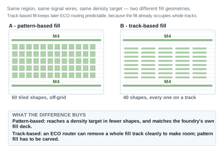
Pattern-based fill tiles a foundry-defined pattern into empty space wherever it legally fits, ignoring the routing track grid. It reaches a density target in fewer shapes and matches the foundry's own fill deck most closely.
Track-based fill places every fill shape on a routing track, at track width, so the result looks like unused routing rather than tiled boxes. It costs more shapes for the same density. In exchange, a later ECO router can remove a whole fill track cleanly to make room for a new wire, where pattern fill has to be carved out around the new route.
The choice is not usually free-standing. A foundry deck often specifies pattern fill on the layers closest to the transistors, where its tighter match to the qualified process matters most, and leaves the choice open on upper routing layers, where ECO friction matters more than process match. Reading the deck's own layer-by-layer fill specification before setting this parameter chapter-wide avoids re-running the whole flow because one layer needed the other geometry.
Step three: choose floating or tied
Part 2 introduced the distinction and Figure 4 drew it. The decision belongs here.
Floating fill is simpler and cheaper. Its shapes are connected to nothing, so their potential follows whatever couples to them, and that makes each shape a possible path between two signal nets. The consequence is extra delay and extra crosstalk.
Tied fill holds every shape at VSS. It still adds capacitance, so nets still get slower, but the other plate of the capacitor does not move. The load is predictable and it carries no noise between nets.
In most flows the foundry's deck decides this, and there is no decision to make. Where it does not, prefer tied fill on the layers carrying your most sensitive nets, and accept the extra tie geometry as the price. That decision belongs with a senior engineer, not a default first move.
Step four: protect what matters, with timing-driven fill
Fill placed at the minimum legal spacing beside a critical net maximises density and maximises the coupling that net sees. Timing-driven fill leaves a wider keep-clear corridor beside nets you name, so those nets see less coupling.
It is important to be precise about what this does. Timing-driven fill does not fill less overall. It moves fill away from the nets you protected and places it elsewhere. The corridor comes out of the density budget in that region, and if the region was already marginal, the corridor can push a window below the minimum. You have then moved the failure rather than fixed anything.
Name nets for this corridor sparingly. Every net you protect widens the corridor somewhere, and a corridor list built from every net that merely touches the critical path, rather than the handful that actually sit on it, spends density budget protecting nets that were never at risk while leaving less of it for the ones that were. Part 8's own coupling-capacitance figures are for exactly this trade: the setup-slack recovery a named net gets back has to be checked against the density it cost elsewhere, not assumed.
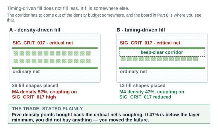
Choosing a corridor width is a negotiation, not a formula. A wide corridor protects the named net well but gives density nowhere to go except neighbouring windows, which can push one of them toward its own maximum. A narrow corridor protects less but stays local. Start narrow, re-measure, and widen only the corridors whose net still shows unacceptable coupling after the first pass.
Name nets sparingly. Every net in the protected list is a net whose local density has to go somewhere else, and a list built from an entire critical path rather than its worst few nets can starve a whole region. Part 8's dashboard is where an over-long list first becomes visible, as a cluster of windows sitting just above their minimum with no margin left.
Step five: insert the fill
Configure and insert metal fill
set_app_options -name signoff.create_metal_fill.runset \
                -value /pdk/nimbus8/fill/nimbus8_fill.rs
set_app_options -name signoff.create_metal_fill.space_to_nets -value 0.120
set_app_options -name signoff.create_metal_fill.space_to_clock_nets -value 0.180
set_app_options -name signoff.create_metal_fill.max_density_threshold \
                -value { {M4 0.72} {M5 0.72} }
set_app_options -name signoff.create_metal_fill.fix_density_errors -value true

signoff_create_metal_fill \
    -mode add \
    -select_layers { M2 M3 M4 M5 M6 M7 } \
    -track_fill generic \
    -timing_preserve_setup_slack_threshold 0.020
Reading the options: signoff.create_metal_fill.runset points at the foundry's fill runset and is the single most important line here. space_to_nets and space_to_clock_nets set the fill-to-signal spacing, with a larger value for clock nets because clocks are the least forgiving victims. max_density_threshold caps density per layer so fill cannot overshoot into erosion territory. fix_density_errors lets the tool honour density rules during insertion, removal and addition rather than only reporting them afterwards.
Reading the command: -mode takes add, overwrite, remove or replace; add is incremental and leaves existing fill in place. -select_layers restricts insertion to named layers, and -all_runset_layers true covers every layer the runset knows about instead. -track_fill chooses off, generic or foundry_node and is what selects track-based rather than pattern-based geometry. -timing_preserve_setup_slack_threshold is the timing-driven behaviour from step four.
Step six: measure again, and query the fill itself
Re-run the density measurement, and this time compare it against the baseline rather than against nothing.
Re-measure density and confirm the fill is really in the block
signoff_report_metal_density

get_shapes -filter "layer_name == M4"
Why query the shapes: a density report is a report. Querying the block confirms the fill geometry is actually present in the design database and will therefore be written at stream-out, rather than existing only in a run directory. It is a thirty-second check that has caught real problems.
The density and fill compliance board
This is the most detailed board in the chapter, and it is the one to come back to.
This is the board the chapter is really about. Read the worst-window figures, not the layer averages: a layer average inside the band tells you almost nothing, because the foundry checks windows. Every minimum and maximum in the Threshold column is owned by the foundry deck, not by the tool.
| Layer | Density before → after | Source command | Foundry threshold | Status | Required action |
|---|---|---|---|---|---|
| Per-layer density, measured in windows | |||||
| M1 | before 61.4% → after 61.4% worst window 44.8% → 44.8% | signoff_ | min 32% / max 78%, 50 um window | PASS | None. M1 is cell-level metal; fill is not inserted on it here. |
| M2 | before 38.2% → after 41.6% worst window 24.1% → 30.9% | signoff_ | min 28% / max 75%, 50 um window | PASS | — |
| M3 | before 35.7% → after 40.8% worst window 22.6% → 29.4% | signoff_ | min 28% / max 75%, 50 um window | PASS | — |
| M4 | before 31.4% → after 47.2% worst window 9.2% → 27.1% | signoff_ | min 25% / max 72%, 100 um window | PASS | — |
| M5 | before 29.8% → after 45.9% worst window 11.7% → 26.5% | signoff_ | min 25% / max 72%, 100 um window | PASS | — |
| M6 | before 44.1% → after 48.3% worst window 19.4% → 24.8% | signoff_ | min 22% / max 70%, 100 um window | PASS | — |
| M7 | before 41.6% → after 46.7% worst window 18.2% → 23.9% | signoff_ | min 22% / max 70%, 100 um window | PASS | — |
| M8 | before 17.3% → after 34.2% worst window 6.1% → 22.7% | signoff_ | min 20% / max 68%, 200 um window | PASS | — |
| M9 | before 14.9% → after 31.8% worst window 4.4% → 21.3% | signoff_ | min 20% / max 68%, 200 um window | PASS | — |
| Layer | Density before → after | Source command | Foundry threshold | Status | Required action |
|---|---|---|---|---|---|
| Fill configuration actually used | |||||
| Fill type | Track-based on M2–M7; pattern-based on M8–M9 | signoff_ | Foundry deck permits both | PASS | — |
| Fill tie | Floating on M2–M5; tied to VSS on M6–M9 | signoff_ with the runset's tie rules | Per the foundry runset | PASS | — |
| Fill-to-signal spacing | Set from the runset; raised on the ADC-bus layers | signoff. | ≥ runset minimum on every layer | PASS | — |
| Timing-driven fill | Enabled; a keep-clear corridor was left beside 42 NDR_ nets and the 16 ADC-bus nets | signoff_ | Corridor must not push any window below minimum | REVIEW | Re-measure the corridor layers after fill. Done in Part 7 step 6: M6 worst window 24.8%, still above the 22% minimum, so the corridor was affordable. Re-classified PASS. |
| Density gradient | Worst adjacent-window step 14.2 points on M4 | signoff. | ≤ 20 points between adjacent windows | PASS | — |
Density verdict for u_sens_tile: 9 layers PASS, 0 REVIEW, 0 BLOCKER after fill → density compliant. Before fill, 4 of 9 layers had at least one window below minimum.
Read it: Compare the two numbers in each Evidence cell. The layer averages move modestly; the worst windows move enormously. M4's average rose from 31.4% to 47.2%, but its worst window rose from 9.2% to 27.1% — and 9.2% was the number that would have failed at the foundry. M1 is unchanged on purpose and says so. A row whose required action is blank is a row that needed nothing, not a row nobody looked at.
Minimum and maximum density values, window sizes and gradient limits come from the foundry's deck. The values shown are illustrative teaching data chosen to be plausible, not a real foundry's numbers.
Window sizes differ by layer here on purpose: lower layers are checked in smaller windows than upper layers, which is normal.
Removing fill
Fill sometimes has to come out: a late ECO needs the space, or a repair in Part 9 requires it locally. signoff_create_metal_fill takes -mode remove for this, and there is also an ECO-aware path for removing track-based fill specifically, which frees whole tracks rather than carving shapes.
Removing fill lowers density. Any removal therefore requires re-measuring density afterwards, and the final density number in the exit state must come from a measurement taken after the last removal, not before it. Part 12 makes that the last step before stream-out for exactly this reason.
Gate — density compliant
- WHY IT MATTERS
- Density is a hard foundry requirement. A layer outside the band is a reason the tape-out is declined, not a quality metric to negotiate.
- WHAT TO CHECK
- Every layer's worst window inside the minimum and maximum; the density gradient inside its own limit; the fill runset version recorded; fill type and tie choice recorded per layer; fill geometry queryable from the block; the density measurement taken after the last metal-adding step.
- EVIDENCE OF A HEALTHY RESULT
- Dashboard 2 reading all layers PASS, with before and after figures for both the layer average and the worst window on each one.
- CONSEQUENCE IF WRONG
- Too little fill means dishing, thin metal, wrong resistance and a possible open. Too much fill means erosion and unnecessary coupling capacitance. Reporting averages instead of worst windows means shipping a failure you had the data to catch.
- SAFE RECOVERY
- Fill is removable. Run
signoff_create_metal_fill -mode removeon the affected layers, correct the options, and insert again. Because fill is the last metal-adding step, removing and re-inserting it does not disturb anything earlier in the order.
Paying the bill that Part 7 ran up
Here is the orientation for this Part. Everything up to now has been building. This Part is the audit. You re-extract the parasitics with all the finishing geometry in place, re-run every electrical check the routing chapter closed, and compare the answers with what you started from. If the numbers have not moved, the measurement is wrong, not the design.
Re-extraction comes first, and it is not optional
A timing report is only as good as the parasitics it was computed from. If you re-run timing without re-extracting, you get the old parasitics with a new timestamp, and it will look reassuring.
Re-extract with the finishing geometry in place
set_extraction_options -virtual_shield_extraction false
set_parasitic_parameters -early_spec maxTLU -late_spec maxTLU

report_qor -summary
report_constraint -all_violators
The one thing to verify: that the extraction actually includes the fill geometry. Fill that exists only in a run directory, and was never written into the block, will not be extracted and will not appear in these numbers. That is why Part 7's last step queried the shapes back out of the block.
Command verification: see Part 3. set_extraction_options, set_parasitic_parameters, report_qor and report_constraint are verified.
What finishing bought — the credit side
Before looking at the cost, record the benefit, so the two can be weighed against each other rather than discussed separately.
This board is the credit side of the ledger. Read it together with Dashboard 4, which is the debit side. Neither board means anything on its own.
| Item | Before → after | Source command / report | Threshold | Status | Required action |
|---|---|---|---|---|---|
| Via redundancy | |||||
| Redundant via rate | 0% → 95.1% (131,486 of 138,240 convertible cuts) | add_, then report_ | ≥ 90% of convertible cuts | PASS | — |
| Vias not converted | 6,754 — 4,102 blocked by adjacent geometry, 2,652 by pin access | redundant via insertion log | Every non-conversion explained | PASS | — |
| Isolated vias remaining | 6,754 → 6,318 after a targeted pass | signoff_ | No further gain without moving signed-off geometry | REVIEW | Stop here. Accepted at 6,318 by explicit decision: the next increment requires a route ECO on timing-closed nets. Recorded in the exit state and handed to Chapter 7. |
| Critical-area reduction | |||||
| Critical area, M2–M7 | 412 → 268 um² per mm² (35% lower) | critical-area report after wire spreading | ≥ 25% reduction where spreading is legal | PASS | — |
| Wire spreading applied | 18,340 segments moved, none by more than 2 tracks | wire spreading log | No segment moved off its assigned layer | PASS | — |
| Wire widening applied | 7,115 segments widened, on M4–M7 only | wire widening log | Widening must not violate the layer maximum density | PASS | — |
| Re-extraction after spreading | Every moved net re-extracted; 3 nets changed slack by more than 5 ps | report_ after re-extraction | No net left un-re-extracted | PASS | — |
| Item | Before → after | Source command / report | Threshold | Status | Required action |
|---|---|---|---|---|---|
| Row content and cell-level finishing | |||||
| Tap cell coverage | 0 → 4,208 tap cells, maximum tie distance 18.0 um | create_ with -distance | ≤ the technology's maximum tie distance | PASS | — |
| Boundary cell verification | 0 → 1,964 boundary cells; 0 placement violations | set_, then check_ | 0 boundary cell violations | PASS | — |
| Filler cell coverage | Rows 100% continuous; 0 remaining gaps | create_, then check_ | 0 gaps, 0 legality violations | PASS | — |
| Filler cells removed for DRC | 31 fillers removed and re-inserted with a narrower cell | remove_ | 0 filler-induced DRC violations | PASS | — |
| MIM capacitors | Not used on this partition | create_ | Used only where the power plan calls for it | PASS | — |
Manufacturability verdict for u_sens_tile: 10 PASS, 1 REVIEW, 0 BLOCKER → accepted.
Read it: Every row here is an improvement, and every improvement was paid for. The redundant via rate reached 95.1%, not 100%, and the Required action column says why that is the right answer rather than a shortfall: the remaining 4.9% are vias where a second cut does not physically fit. Chasing them with a higher effort setting buys tenths of a percent and risks moving geometry that is already signed off.
Field values are this chapter's illustrative teaching data.
What finishing cost — the debit side
This is the board the chapter exists to produce. Read the Delta column first, then ask of each row whether that delta is affordable on this design.
This is the board that makes the chapter honest. Dummy fill touches no signal wire and changes no logic, and it still moved every number below. If this board showed no change, the measurement would be wrong, not the design.
| Measurement | Before → after finishing | Delta | Threshold | Status | Required action |
|---|---|---|---|---|---|
| Setup timing | |||||
WNS setup, func_ | +0.011 ns → +0.006 ns | −0.005 ns | ≥ 0 ns | PASS | — |
TNS setup, func_ | 0 ns → −0.018 ns across 4 paths, then 0 ns after a scoped ECO | 0 ns after repair | = 0 ns | REVIEW | Four paths went negative on re-extraction after fill. Repaired by a scoped postroute ECO in Part 8 step 4, then re-measured. Recorded, not hidden. |
WNS setup, test_ | +0.015 ns → +0.011 ns | −0.004 ns | ≥ 0 ns | PASS | — |
| Hold timing | |||||
WNS hold, func_ | +0.019 ns → +0.021 ns | +0.002 ns | ≥ 0 ns | PASS | — |
TNS hold, func_ | 0 ns → 0 ns | 0 ns | = 0 ns | PASS | — |
| Measurement | Before → after finishing | Delta | Threshold | Status | Required action |
|---|---|---|---|---|---|
| Signal integrity and electrical limits | |||||
| Maximum transition violators | 0 → 2, then 0 after repair | 0 after repair | = 0 | REVIEW | Two nets on M6 exceeded max transition once fill capacitance was included. Fixed by upsizing two drivers in Part 8 step 4. |
| Maximum capacitance violators | 0 → 0 | 0 | = 0 | PASS | — |
| Total coupling capacitance | 1.00x → 1.13x of the pre-finishing total | +13% | ≤ +20%, by local convention | PASS | — |
| Crosstalk delay violators | 0 → 0 | 0 | = 0 | PASS | — |
| Crosstalk noise violators | 0 → 0 | 0 | = 0 | PASS | — |
| Power | |||||
| Dynamic power | 1.87 mW → 1.94 mW | +0.07 mW (+3.7%) | ≤ +5% | PASS | — |
| Leakage power | 0.097 mW → 0.103 mW | +0.006 mW (+6.2%) | ≤ +10% | PASS | — |
Electrical verdict for u_sens_tile after finishing: 9 PASS, 2 REVIEW, 0 BLOCKER → accepted, with the two REVIEW rows carried into the exit state.
Read it: Read the Delta column first, then ask whether each delta is affordable. Setup slack on func_ss_0p72v_125c fell from +0.011 ns to +0.006 ns. That is still positive, so it passes — but roughly half the margin the routing chapter worked to win was spent here, by a step that added no logic. A design that entered finishing at +0.002 ns would have left it negative.
Every value was measured on re-extracted parasitics that include the fill geometry. Measuring after fill on pre-fill parasitics is the single most common way to miss this entirely.
Reading the two boards together
Taken alone, Dashboard 3 says finishing was a success: redundant via rate from zero to 95.1 percent, critical area down thirty-five percent, every row continuous, every well tied. Taken alone, Dashboard 4 says finishing cost five picoseconds of setup margin, briefly broke four paths and two transition limits, and raised total coupling capacitance by thirteen percent.
Both are true, and neither is the answer. The answer is that on this design the trade was worth making, and it was worth making because there was margin to spend. The routing chapter left +0.011 nanoseconds of setup slack. Finishing spent five picoseconds of it and left +0.006.
Now consider the same work on a design that entered finishing at +0.002 nanoseconds. The same fill would have taken it negative. The correct response there is not to skip fill, because density is not optional. It is to find timing margin before starting finishing, or to plan for timing-driven fill and a tighter corridor from the outset.
Repairing what finishing broke
Two rows on Dashboard 4 are REVIEW rather than PASS, and both were repaired rather than accepted. It is worth walking through how, because the repair is constrained in a way that postroute optimization in the routing chapter was not.
The four setup paths
Four paths went negative when re-extracted after fill. Total negative slack was −0.018 nanoseconds across all four, so none of them was badly broken.
The constraint is that the fix must not disturb the density you just achieved. Rerouting a net removes fill around the old route and requires fill around the new one, which changes local density in both places. So the repair is scoped as tightly as possible: resize drivers where that is enough, and only reroute where it is not.
Identify and scope the repair
report_timing -delay_type max -nworst 20 -max_paths 20 \
              -scenarios func_ss_0p72v_125c

report_constraint -all_violators
What you are deciding: for each failing path, whether it can be fixed by cell resizing alone. A resize changes no routed geometry and therefore disturbs no fill. A reroute does both. Prefer the resize even when it is a slightly worse fix, because the second-order cost of the reroute is real and easy to forget.
The two transition violations
Two nets on M6 exceeded maximum transition once fill capacitance was included. Both were fixed by upsizing the driver, which changes no routed geometry at all.
Notice why M6 and not a lower layer. M6 carries the ADC bus, which the routing chapter routed on M6 and M7 with a shielded non-default rule. Long wires with high capacitance and no slack to spare are exactly where an extra thirteen percent of coupling capacitance shows up first. Knowing which nets are most exposed before you fill is how you predict where the repairs will be.
Re-measure after repair
Every repair changes parasitics, so the loop closes only when a measurement taken after the last repair is clean. This is a measured loop with an exit condition, not a fixed number of iterations.
| Step | Action | Exit when |
|---|---|---|
| 1 | Re-extract with finishing geometry in place | Extraction includes the fill; verified by querying shapes from the block |
| 2 | Measure timing, transition, capacitance, crosstalk and power | Every number recorded against its pre-finishing baseline |
| 3 | Triage: resize where possible, reroute only where necessary | Every violator has a chosen repair, and its second-order cost is known |
| 4 | Apply the repairs | The repair is scoped to named objects, not applied globally |
| 5 | Re-extract and re-measure | WNS ≥ 0 and TNS = 0 in every scenario, with no new violator |
| 6 | If any net was rerouted, re-measure density | Every layer still inside its band after the reroute |
Power
Power moves too, and in two different ways.
Dynamic power rose from 1.87 to 1.94 milliwatts, a 3.7 percent increase. That is coupling capacitance: more capacitance to charge and discharge on every transition. It is a direct, expected consequence of fill and scales with how much fill you inserted.
Leakage rose from 0.097 to 0.103 milliwatts, a 6.2 percent increase. That is not fill. Fill leaks nothing. That is the thousands of filler cells, tap cells and boundary cells added in Part 5, each contributing a small leakage current. It is a cell-count effect, and it is one reason filler cell choice is not entirely free.
Gate — electrical closure after finishing
- WHY IT MATTERS
- The timing signed off in the routing chapter describes a design that no longer exists. Until this gate passes, nothing about this design's timing is known.
- WHAT TO CHECK
- Parasitics re-extracted with fill present and verified to include it; WNS and TNS for setup and hold in every scenario; maximum transition and maximum capacitance violator counts; crosstalk delay and noise; dynamic and leakage power; each one recorded before and after with a delta.
- EVIDENCE OF A HEALTHY RESULT
- Dashboard 4 with every row carrying both numbers and a delta, WNS positive and TNS zero in every scenario, and zero violators in every other category after repair.
- CONSEQUENCE IF WRONG
- Signing off timing on pre-fill parasitics is the most serious error available in this chapter. It produces a clean report for a design that is not the one being manufactured, and nothing downstream will catch it.
- SAFE RECOVERY
- If fill cost more margin than the design has, remove fill on the worst-affected layers, raise the timing-driven corridor, and re-insert. If that still does not close, the shortfall is upstream and the honest response is to return to postroute optimization for more margin rather than to under-fill.
Passing this gate closes the electrical half of the chapter's argument, but it does not close the chapter. Every number Dashboard 4 just certified describes geometry that has not yet been checked against the foundry's actual rule deck — the router's own DRC and this chapter's density band are both internal approximations. Part 9 runs that outside check next, and because it is a separate tool reading the same geometry, a design that passes here can still fail there.
Checking against the foundry's rules, not the router's
Here is the orientation for this Part. Up to now every check has been the tool marking its own homework. Signoff DRC is the first time the design is checked against the foundry's actual rule deck, by a dedicated verification engine that was written for that job and nothing else. Think of it as sending the manuscript to the copy-editor after the spell-checker has already passed it.
Two things arrive at this Part already true, and it is worth stating them before the first check runs. Every metal-adding and metal-moving step in the chapter has finished, so the geometry being checked here is the geometry that will actually ship. And every earlier check in the flow, including the router's own DRC, has already passed. Signoff DRC does not repeat that work. It looks for what those checks were never built to see.
Running the check
Run signoff design-rule checking
set_app_options -name signoff.check_drc.run_dir \
                -value ./signoff_drc_run
set_app_options -name signoff.check_drc.read_layout_views -value true

signoff_check_drc \
    -error_data drc_run_1 \
    -check_all_runset_layers true
Reading the arguments: -error_data names the error data view the results are written into, so successive runs can be compared rather than overwriting each other. -check_all_runset_layers true checks every layer the runset knows about; -select_layers and -select_rules narrow it, and -unselect_rules excludes named rules. -coordinates and -excluded_coordinates restrict the check to regions, which is how an incremental check after a local repair is run quickly.
Triaging the results
A first signoff DRC run on a design that has never been through one will return a large number. On the Nimbus-8 sensor tile it returned 1,284. That number is not alarming by itself, because violations cluster: a handful of root causes typically produce most of the count.
Sort by rule name before doing anything else. A thousand violations of one rule is one problem. A thousand violations spread across two hundred rules is a different and much worse situation, usually meaning the wrong runset or the wrong process version.
Then triage every violation into one of three branches.
| Branch | What it means | What you do |
|---|---|---|
| Autofix may touch it | A local geometric violation the router can repair inside the rules you set, without moving anything timing-critical. | Run signoff_fix_drc, scoped to those rules. |
| Needs a manual or ECO fix | Repairing it requires moving routed geometry, changing placement, or removing fill in a way that has second-order consequences. | A scoped route ECO or placement change, then re-extract and re-measure density. |
| Will be waived | The geometry is a known, accepted pattern the foundry has agreed to accept, or a rule that does not apply to this construct. | Document the waiver with the rule name and the reason, and record it in the handoff. |
The three branches are not equally sized in practice, and knowing the shape in advance helps you plan the loop. Autofix typically clears the large majority of a first check's count in one pass, because most violations are local spacing and enclosure problems the tool's own repair rules were written to handle. The manual and ECO branch is small by count but large by effort, since each one needs a human decision about what may move. The waived branch should stay close to empty; a rule waived for convenience rather than for a genuine, documented exception is a rule you have quietly stopped checking.
Part 10's worked example shows the shape in real numbers. The first check on u_sens_tile returned 1,284 violations. A scoped autofix pass cleared 1,094 of them immediately — the large majority the paragraph above describes. Of the 190 that remained, 174 were cleared by a second, narrower autofix pass targeting the specific rule families still open, and the last 16 needed a scoped route ECO each. Zero were waived. Three check-and-fix loops closed the count to zero in total, which is itself a data point: a loop that has not converged after three or four passes is usually not going to converge on autofix alone, and is a sign to move violations into the manual branch rather than keep re-running the same repair.
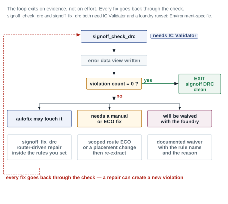
signoff_check_drc, marked with a blue tag reading “needs IC Validator”. It writes an error data view, then reaches the decision “violation count = 0?”. The green “yes” branch runs right to an EXIT box reading “signoff DRC clean”. The red “no” branch runs down and splits three ways: violations autofix may touch, violations needing a manual or ECO fix, and violations that will be waived with the foundry, each with the action underneath it. The dashed red path at the far left returns from the autofix branch all the way back to the check at the top, and the note beside it says why: every fix goes back through the check, because a repair can create a new violation.Notice what the loop does not do: it never assumes a repair worked. Every branch, including the one waived with the foundry, ends by returning to the top and counting again. That discipline is what makes the exit condition trustworthy. A count of zero at the end of this loop means zero on the geometry that exists right now, not zero on the geometry that existed before the last repair.
A loop needs a stop condition beyond zero violations, because a hard violation that no repair touches will otherwise run forever. Bound the iteration count before the first run, watch whether the count is falling on each pass, and treat a loop that stops falling before it reaches zero as a design question, not a tool setting to push higher.
Autofix
Repair violations automatically, inside limits you set
set_app_options -name signoff.fix_drc.max_errors_per_rule -value 2000
set_app_options -name signoff.fix_drc.fix_detail_route_drc -value true

signoff_fix_drc \
    -start_repair_loop 1 \
    -max_number_repair_loop 3 \
    -select_rules { M4.S.1 M5.S.1 V4.EN.2 }
Reading the arguments: -start_repair_loop and -max_number_repair_loop bound how many repair iterations run, which matters because an unbounded loop on a hard violation will run for a very long time and achieve nothing. -select_rules restricts repair to named rules and is the argument that keeps autofix on a leash; -unselect_rules is its complement. -coordinates restricts repair to a region.
The judgment: autofix invokes the router to repair geometry. On a design whose timing is closed, letting it loose on every rule at once is how you discover, three hours later, that it fixed eleven hundred violations and broke nine timing paths. Name the rules. Start with the ones whose repair is local and geometric.
Double patterning
On processes that use double patterning, some layers are manufactured in two exposures, and every shape on such a layer must be assigned to one of two masks. Shapes too close together must be on different masks. Sometimes the geometry makes that impossible, because a loop of shapes forces a contradiction. That is an odd-cycle violation.
An odd cycle cannot be fixed by recolouring, since no colouring exists. It can only be fixed by changing the geometry so the cycle is broken. The tool supports odd-cycle fixing as part of the signoff DRC repair flow, and it is worth knowing this class exists so that a violation which resists every ordinary repair is recognised rather than retried.
PG augmentation
Power and ground augmentation adds extra supply metal after routing, into space that turned out to be free. More supply metal lowers IR drop and improves electromigration margin, and it costs nothing in function.
It belongs before fill in the order, because it adds metal and therefore density. Filling first and augmenting afterwards can push windows over the maximum.
The metal it adds is not automatically free of the antenna and critical-area concerns the rest of this chapter spends so much effort on, since it is still real shapes on real layers, connected to a net that genuinely matters — the supply mesh. A guided or timing-driven augmentation pass that targets only the regions actually short of margin, rather than a standard pass applied everywhere, keeps that added metal from becoming density this chapter's own fill budget then has to make room for. A standard pass is the right default only when no IR-drop or electromigration report yet exists to guide a narrower one; once that report exists, use it.
Augment the power and ground mesh
set_app_options -name signoff.create_pg_augmentation.power_net_name -value VDD
set_app_options -name signoff.create_pg_augmentation.ground_net_name -value VSS

signoff_create_pg_augmentation \
    -node generic \
    -mode add
Reading the arguments: -node selects a process node from a fixed list of foundry nodes plus generic, because augmentation geometry is node-specific. -mode takes add, remove, remove_dangling_mesh, remove_by_drc, remove_by_drc_auto and trim_pga_by_timing. The last of these is the timing-aware trim: it removes augmentation shapes that cost more in coupling than they buy in supply robustness, which is the same trade this whole chapter is about, applied to power metal.
What to verify afterwards: that no dangling augmentation shapes remain, and that PG connectivity is unchanged. An augmentation shape connected at one end only adds capacitance and provides no current path, which is the worst of both.
Isolated via repair
Part 6 left 6,754 vias unconverted. signoff_fix_isolated_via takes a second pass at them through the signoff engine, and can update track fill at the same time so that freeing a track for a redundant cut does not leave a density hole. On the Nimbus-8 sensor tile it reduced the count from 6,754 to 6,318.
That is a 436-via improvement, and then the numbers stop moving. The remaining cases need routed geometry to move. At that point the right answer is to stop and record the residual, which is what Dashboard 3 and Dashboard 5 both do.
Gate — signoff DRC clean
- WHY IT MATTERS
- This is the check the foundry will run. Anything it finds that you did not will be found later, by someone with less context and a worse schedule.
- WHAT TO CHECK
- Violation count zero, or every remaining item waived in writing with its rule name and reason; every repair re-checked rather than assumed; density re-measured after any autofix pass that touched fill layers; PG augmentation verified with no dangling shapes.
- EVIDENCE OF A HEALTHY RESULT
- A final
signoff_check_drcrun returning zero, in an error data view that can be reopened, with the runset version recorded alongside it. - CONSEQUENCE IF WRONG
- A missed signoff DRC violation is a tape-out blocker discovered at the foundry. An undocumented waiver is worse, because it looks like a pass to everybody downstream.
- SAFE RECOVERY
- Error data views are named and persistent, so an earlier run can always be reopened and compared. If autofix made things worse, reopen the checkpoint saved before it and repair a narrower set of rules.
Chip finishing on u_sens_tile, end to end
Here is the orientation for this Part. Everything so far has been the method. This is the method applied once, to a real partition, in order, with the numbers written down at every step. Follow it as a narrative rather than a recipe: the interesting content is the decisions, not the command lines, which you have already seen.
The design, and what it inherits
The teaching design is Nimbus-8: 9.90 million standard cells, 72 SRAM macros, one DDR PHY hard macro, a 3.20 by 3.20 millimetre core, and four clocks at 1.60 gigahertz, 1.10 gigahertz, 800 megahertz and 200 megahertz.
As in the routing chapter, the worked example runs on one named partition rather than the whole design. That partition is u_sens_tile, the sensor-interface tile carrying the ADC input bus: 46,200 standard cells, 2 of Nimbus-8's 72 SRAM macros, 0.70 by 0.62 millimetres, which is 0.434 square millimetres, at 79.6 percent utilization.
| Item | Value on arrival |
|---|---|
| Routed percentage | 100% — 0 unrouted nets |
| Opens / shorts | 0 / 0 |
| Routing DRC violations | 0 |
| Antenna violations | 0 |
| Congestion overflow H / V | 0% / 0% |
WNS setup, func_ss_0p72v_125c | +0.011 ns |
TNS setup, func_ss_0p72v_125c | 0 ns |
WNS setup, test_ss_0p72v_125c | +0.015 ns |
WNS hold, func_ff_0p88v_m40c | +0.019 ns |
TNS hold, func_ff_0p88v_m40c | 0 ns |
| Max transition / max capacitance violators | 0 / 0 |
| Crosstalk delay / noise violators | 0 / 0 |
| Dynamic / leakage power | 1.87 mW / 0.097 mW |
| Total wire length | 842,300 µm |
| Via count | 138,240 |
| Non-default-rule nets | 42 on NDR_WIDE_2X; 16 ADC-bus nets on NDR_SHIELD_2X |
| Layer usage | M2–M9 available; M6/M7 reserved for the ADC bus |
| Entry checkpoint | nimbus8_sens_tile_routed_postopt_v1 |
Step 1 — Reopen, re-verify, save a recovery point
The checkpoint opened cleanly, with two informational messages and no warnings. All three connectivity and rule checks returned zero, matching the routing exit record exactly.
Density was recognised as unmeasured and classified REVIEW on Dashboard 1, with the action deferred to step 8. The pre-finishing recovery point nimbus8_sens_tile_pre_finish_v1 was saved before anything else ran.
Verdict: PASS — 13 PASS, 1 REVIEW with a stated action, 0 BLOCKER.
Step 2 — Tap cells
The technology specifies a maximum well-tie distance of 20.0 microns. Taps were inserted at 18.0 microns with the every_row pattern, giving margin against the limit rather than sitting on it.
4,208 tap cells were inserted, prefixed TAP_. The maximum realised tie distance was 18.0 microns, comfortably inside the 20.0 micron rule. No tap walls or meshes were used: this partition has one voltage domain and no analogue neighbour, so the uniform array is the right and cheapest answer.
Verdict: PASS.
Step 3 — Boundary cells
Boundary cell rules were declared for left, right, top and bottom edges, and then compiled across all targets. 1,964 boundary cells were inserted, and check_boundary_cells returned zero violations.
Boundary cell insertion also created routing guides and placement blockages along the row ends, as expected. They were left in place.
Verdict: PASS.
Step 4 — Critical-area reduction
Wire spreading moved 18,340 segments, none by more than two tracks. Wire widening widened 7,115 segments, restricted to M4 through M7. M2 and M3 were excluded because their density was already healthy and widening there would have pushed windows towards the maximum for no yield gain.
Critical area on M2 through M7 fell from 412 to 268 square microns per square millimetre, a 35 percent reduction.
Every moved or widened net was re-extracted. Three nets changed setup slack by more than five picoseconds, and all three remained positive. The worst was SIG_CRIT_038 at +0.014 nanoseconds, down from +0.021. That is a real cost and it was recorded rather than absorbed.
Verdict: PASS.
Step 5 — Redundant vias
The via mapping table was reported first and found to contain entries for every via definition the design uses, so no custom mappings were added.
Insertion ran at high effort with setup and hold preserve thresholds of 0.020 nanoseconds, so vias on nets inside that margin were left alone. 131,486 of 138,240 cuts converted, a rate of 95.1 percent. Of the 6,754 that did not, 4,102 were blocked by adjacent geometry and 2,652 by pin access.
Verdict: PASS, with the residual recorded.
Step 6 — Antenna repair
Wire widening in step 4 increased the metal area attached to several gates, and check_routes -antenna true found 41 new violations on nets that had been clean at routing exit. All 41 were on widened M4 and M6 segments, which is exactly where the widening ran.
Diodes were inserted for all 41. Because the route is closed, each diode went into the nearest free site with a stub connecting it, rather than abutting the gate as it would have during routing. This ran before filler insertion, so free sites still existed. A re-check returned zero.
Verdict: PASS. Note that this step existed only because step 4 happened. That is the order dependency from Part 4 doing its job.
Step 7 — Filler cells
Fillers were inserted from a descending width list, closing every remaining gap. check_legality -chipfinishing auto returned zero violations.
31 fillers were then found to create design-rule violations against their neighbours. They were removed with remove_stdcell_fillers_with_violation and the gaps re-filled with narrower cells under a distinct prefix. A re-check returned zero.
Verdict: PASS.
Step 8 — Density baseline
This is where Dashboard 1's REVIEW gate is discharged. Density was measured for the first time on this design.
Four of nine layers had at least one window below the minimum. The worst was M9, at 4.4 percent against a 20 percent minimum. M8 was next at 6.1 percent, then M4 at 9.2 percent and M5 at 11.7 percent. No layer exceeded its maximum anywhere.
The pattern is exactly what a heat map would predict. The upper layers are the emptiest, because routing uses them least. The middle layers are healthier. Nothing was surprising, which is itself worth recording: a surprising density baseline usually means a floorplan problem rather than a fill problem.
Verdict: BLOCKER until fill. Four layers are outside the band and the design cannot be taped out in this state.
Step 9 — PG augmentation
Augmentation ran before fill, so that fill would see the augmented mesh and size itself against it. Extra VDD and VSS metal was added into space that routing had left free, and the result was verified to contain no dangling augmentation shapes and to leave PG connectivity unchanged.
Verdict: PASS.
Step 10 — Metal fill
Three decisions were made before the command ran, and each was written down.
- Fill type. Track-based on M2 through M7, where ECO routing is likely. Pattern-based on M8 and M9, where routing is sparse and ECOs rarely reach.
- Tie. Floating on M2 through M5, tied to VSS on M6 through M9. The foundry deck permits both; M6 and M7 carry the shielded ADC bus, and tied fill there keeps the coupling those nets see predictable.
- Timing-driven corridor. Enabled, with a wider keep-clear corridor beside the 42
NDR_WIDE_2Xnets and the 16 ADC-bus nets.
After insertion, all nine layers were inside the band. M4's worst window rose from 9.2 to 27.1 percent, M9's from 4.4 to 21.3 percent. The worst window on the whole design is now M9 at 21.3 percent against a 20 percent minimum, which is inside the band with little margin and is worth noting in the handoff.
The timing-driven corridor was then checked against the density it cost. M6, which carries the corridor, came out at a 24.8 percent worst window against a 22 percent minimum. The corridor was affordable. Dashboard 2's one REVIEW row is exactly this check, and it was re-classified PASS once the number came back.
Verdict: PASS. Density compliant on every layer.
Step 11 — Re-extract and re-close timing
Parasitics were re-extracted with the fill in place, verified by querying fill shapes back out of the block first.
Setup worst negative slack on func_ss_0p72v_125c fell from +0.011 to +0.004 nanoseconds, and four paths went negative with a total negative slack of −0.018 nanoseconds. Two nets on M6 exceeded maximum transition. Coupling capacitance rose 13 percent overall. Hold improved very slightly, from +0.019 to +0.021 nanoseconds, which is the expected direction: extra capacitance slows data paths, and slower data helps hold.
Repairs were scoped tightly. Both transition violations were fixed by upsizing drivers, which moves no routed geometry. Three of the four setup paths were fixed by resizing. The fourth needed a short reroute on one segment, and because that reroute disturbed fill locally, density was re-measured afterwards on the affected layer and confirmed still inside the band.
Final state: WNS setup +0.006 nanoseconds, TNS setup 0, WNS hold +0.021 nanoseconds, TNS hold 0, zero transition and capacitance violators, zero crosstalk violators.
Verdict: PASS, with two REVIEW rows on Dashboard 4 recording what had to be repaired.
Step 12 — Signoff DRC
The first run returned 1,284 violations. Sorted by rule, 1,102 of them were two rules: a fill-to-signal spacing rule on M4 and M5, and a via enclosure rule on V4. Both are exactly what steps 5 and 10 would be expected to produce.
Autofix was run, scoped to those two rule families only, with the repair loop bounded at three. It cleared 1,094. The remaining 190 were triaged: 174 were fixed by a second, narrower autofix pass, and 16 needed scoped route ECOs.
Three check-and-fix loops were needed in total. The third returned zero. No waivers were used.
Because autofix had removed fill in places to make room, density was re-measured after the last repair. All nine layers were still inside the band, with M9's worst window at 21.3 percent unchanged.
Verdict: PASS.
Step 13 — Isolated vias, then save and stream out
signoff_fix_isolated_via reduced the unconverted count from 6,754 to 6,318. Further passes achieved nothing without moving routed geometry, so the count was accepted and recorded.
The final block was saved as nimbus8_sens_tile_finished_v1 and confirmed to reopen cleanly. GDSII was written, and the exact layer map file used was recorded alongside it in the handoff.
Verdict: GO.
Nothing in the checkpoint name or the GDSII file states any of this on its own. The evidence that nimbus8_sens_tile_finished_v1 is actually ready lives in the thirteen verdicts above it, and in the reports each one cites. That is what a handoff record is for: not the file, but the trail that says the file may be trusted.
The layer map deserves the same scrutiny as the geometry itself. It is the only place that says which drawn layer becomes which mask, and a design and a layer map that individually check out can still produce a wrong GDSII together if the map does not match the tape-out the geometry was actually signed off against. Recording the exact map file alongside the checkpoint, not just its name, is what lets a downstream consumer confirm they are opening what this handoff actually describes.
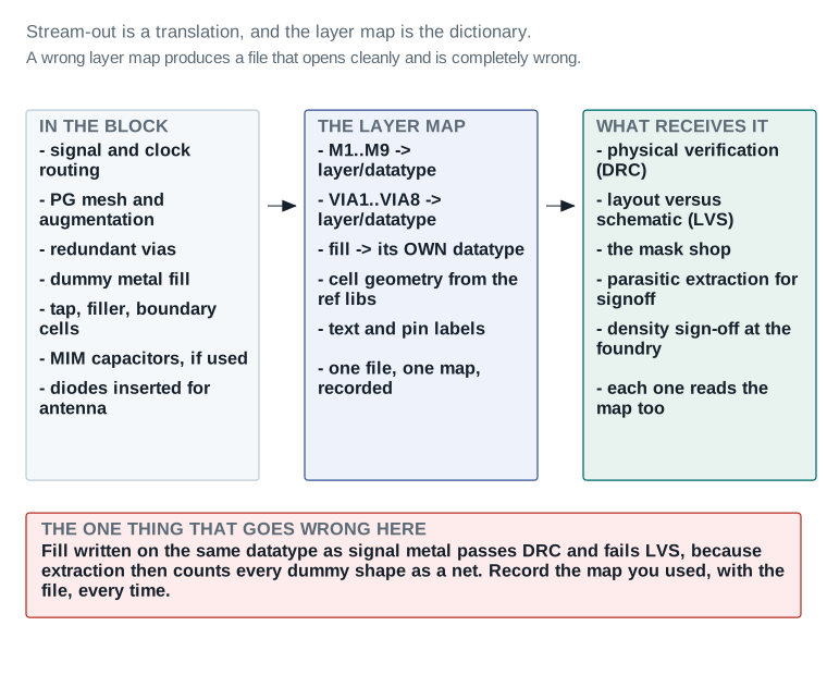
The whole example in one table
| Step | Key numbers | Verdict |
|---|---|---|
| 1. Reopen and re-verify | 13 PASS, 1 REVIEW (density unmeasured) | PASS |
| 2. Tap cells | 4,208 taps, 18.0 µm interval against a 20.0 µm rule | PASS |
| 3. Boundary cells | 1,964 cells, 0 violations | PASS |
| 4. Critical-area reduction | 18,340 spread, 7,115 widened; 412 → 268; 3 nets re-timed | PASS |
| 5. Redundant vias | 131,486 / 138,240 = 95.1%; 6,754 residual, explained | PASS |
| 6. Antenna repair | 41 new violations from step 4; 41 diodes; re-check 0 | PASS |
| 7. Filler cells | Rows continuous; 31 fillers replaced for DRC | PASS |
| 8. Density baseline | 4 of 9 layers below minimum; worst window M9 at 4.4% | BLOCKER until fill |
| 9. PG augmentation | 0 dangling shapes; PG connectivity unchanged | PASS |
| 10. Metal fill | 9 of 9 layers inside band; worst window M9 at 21.3% | PASS |
| 11. Re-extract, re-close | WNS setup +0.011 → +0.004 → +0.006 after repair | PASS |
| 12. Signoff DRC | 1,284 → 0 in 3 loops; 0 waivers; density re-checked | PASS |
| 13. Isolated vias, save, stream out | 6,754 → 6,318; nimbus8_sens_tile_finished_v1 | GO |
Do it yourself, and get it wrong once on purpose
Here is the orientation for this Part. Reading about a cost is not the same as watching a number move. This lab is built so that you break something deliberately in the middle of it, see the consequence in a report, and then fix it. That is the part you will remember.
Exercise 1 — Establish the baseline
Open a routed, timing-closed block. Before running any finishing command, record six numbers: worst negative slack for setup in your worst corner, worst negative slack for hold, total negative slack for both, dynamic power, and leakage power. Save them in a file, not in your head.
Close with: a file containing six numbers and the checkpoint name they came from. PASS if the file exists before any finishing command has run.
Exercise 2 — Save a recovery point
Save the block under a name that states the design, the partition, the stage boundary and a version. Then close it and reopen it from that name, to prove it reopens.
Close with: a checkpoint that reopens with no unexplained message. PASS if reopening produces the same report output as before saving.
Exercise 3 — Insert taps, and check the interval you chose
Find the maximum well-tie distance in your technology file or library documentation. Do not guess it. Insert tap cells at a distance comfortably inside it, with a prefix.
Then count the taps you inserted and check the count against the arithmetic: core area divided by the square of the tap pitch, roughly. If the count is wildly different from that estimate, something is wrong with the pattern or the voltage-area argument.
Close with: a tap count, the interval used, and the technology limit it was checked against. PASS if the interval is inside the limit and the count is within about twenty percent of the estimate.
Exercise 4 — Insert boundary cells and fillers, in the right order
Declare boundary cell rules, compile them, and check. Then insert fillers from a descending width list. Then check legality with the chip-finishing option.
Close with: zero from the boundary cell check and zero from the legality check. PASS on both zeros.
Exercise 5 — The deliberate mistake
This is the exercise that teaches the chapter. You are going to do step 7 and step 11 of Part 4's order in the wrong sequence, on purpose.
- Re-extract parasitics and record worst negative slack for setup. Call this number A.
- Now insert metal fill, with whatever settings your foundry deck permits.
- Without re-extracting, re-run your timing report. Record worst negative slack. Call this B.
- Now re-extract, and run the timing report again. Record worst negative slack. Call this C.
You will find that B equals A, and C does not. That is the whole lesson. Re-running timing without re-extracting produced a clean-looking report for a design that had already changed. Nothing warned you. The report was not wrong about the parasitics it was given; it was given the wrong parasitics.
Close with: three numbers, A, B and C, and one sentence explaining why B is useless. PASS if C differs from A and you can say why.
Exercise 6 — Measure density before and after
Reopen your recovery point so the deliberate mistake is discarded. Measure density before inserting any fill and record, per layer, both the layer average and the worst window.
Then insert fill and measure again. Build a small table with four columns: layer, average before, average after, worst window before, worst window after.
Look at which column moved most. On almost every design it will be the worst window, not the average.
Close with: the table. PASS if every layer's worst window is inside the foundry band, and you can name which layer had the least margin.
Exercise 7 — Price the timing-driven corridor
Pick your five most timing-critical nets. Insert fill twice: once without a timing-driven corridor, once with one protecting those nets.
Record, for both runs, the worst negative slack on those five nets and the worst window density on the layers they run on.
You have now measured the trade directly: how much density the corridor cost, and how much slack it bought. Decide whether you would take it.
Close with: four numbers and a one-sentence decision with a reason. PASS if the decision names both the density cost and the slack gained.
Exercise 8 — Write the exit state
Produce the handoff record. It must contain per-layer density after fill, the redundant via rate, critical area before and after, the fill type and tie choice per layer, signoff DRC status with any waivers named, final timing per scenario, and the saved checkpoint name.
Then give it to somebody who did not do the work and ask whether they could start the next stage from it. If they have to ask you a question, the record is incomplete.
Close with: the record, and a named checkpoint that reopens. PASS if a colleague can read it without asking you anything.
Lab close-out
| Exercise | Closes with | Your result |
|---|---|---|
| 1. Baseline | Six numbers, recorded before any finishing command | PASS / REVIEW / BLOCKER |
| 2. Recovery point | A checkpoint that reopens cleanly | PASS / REVIEW / BLOCKER |
| 3. Tap cells | Interval inside the technology limit; count sane | PASS / REVIEW / BLOCKER |
| 4. Boundary and filler cells | Zero from both checks | PASS / REVIEW / BLOCKER |
| 5. The deliberate mistake | A, B and C, and why B is useless | PASS / REVIEW / BLOCKER |
| 6. Density before and after | Per-layer table; every worst window inside the band | PASS / REVIEW / BLOCKER |
| 7. Corridor pricing | Density cost, slack gained, and a decision | PASS / REVIEW / BLOCKER |
| 8. Exit state | A record a colleague can use without asking you | PASS / REVIEW / BLOCKER |
A lab result of eight PASS means you can run this stage. A REVIEW on exercise 5 or 6 means the two most important ideas in the chapter have not landed yet, and those two are worth repeating before moving on.
The handoff to signoff
Here is the orientation for this Part. Everything the chapter has built now has to leave the tool and go to people who cannot ask you questions: a verification team, a mask shop, a foundry. This Part decides whether it is ready, writes it out, and records what was written and how.
The final ordering, and why density is measured last
Two things happen near the end that change density, and both happen after the fill step. Signoff DRC autofix can remove fill to make room for a repair. A scoped route ECO in Part 8 removes fill along the old route.
So the density number that goes into the handoff must come from a measurement taken after the last of those, not from the measurement taken when fill was inserted. This is the single most common way a handoff record ends up containing a number that was true an hour earlier.
The same logic applies to every other number in the handoff, not only density. Timing, power, LVS readiness, and the antenna check all need to be measured after the last operation capable of moving them, or the record is a snapshot of a design that no longer exists. The sequence below exists to put every measurement after everything that could invalidate it.
Treat the order below as load-bearing, not as a checklist to be run in any convenient sequence. Moving a single line ahead of an operation it depends on reproduces exactly the density-after-augmentation and timing-before-fill mistakes Part 4 spent its whole ordering table warning against, at the one point in the flow where there is no later step left to catch it.
The final sequence, in order
signoff_check_drc -error_data drc_final

signoff_report_metal_density

check_lvs -checks { short open floating_routes }
check_legality -chipfinishing auto
check_boundary_cells
check_routes -antenna true

report_qor -summary
report_power

save_block -as nimbus8_sens_tile_finished_v1
Why in this order: DRC first, because its repairs change geometry. Density second, because it must reflect those repairs. The four structural checks next, because they are fast and independent. Timing and power after that. The save last, so the checkpoint contains the state every report above describes.
Command verification: see Part 3. check_lvs, check_legality, check_boundary_cells, check_routes, report_qor, report_power and save_block are verified. signoff_check_drc and signoff_report_metal_density are verified and Environment-specific.
The go / no-go board
One board, one decision. A criterion with no evidence behind it is not a PASS, and a REVIEW with no stated action is an unresolved BLOCKER wearing a friendlier word.
| Item | Evidence | Source command / report | Threshold | Status | Required action |
|---|---|---|---|---|---|
| Physical verification | |||||
| Signoff DRC | 0 violations after 3 check/fix loops (1,284 at first check) | signoff_ | 0, or every remaining item waived in writing | PASS | — |
| Waivers | 0 waivers used | waiver record | Every waiver named, with the rule and the reason | PASS | — |
| LVS readiness | 0 shorts, 0 opens, 0 floating routes; fill on its own datatype | check_ | 0 in every category | PASS | — |
| Placement legality | 0 violations with fillers, taps and boundary cells in place | check_ | 0 violations | PASS | — |
| Boundary cells | 0 placement violations across 1,964 cells | check_ | 0 violations | PASS | — |
| Item | Evidence | Source command / report | Threshold | Status | Required action |
|---|---|---|---|---|---|
| Manufacturability | |||||
| Density compliance | 9 of 9 layers inside the band, worst window 21.3% on M9 against a 20% minimum | signoff_ | Every window inside min and max | PASS | — |
| Fill inserted and queried | Fill present on M2–M9 and queried back from the block | signoff_, then get_ | Fill readable from the block, not only from a report | PASS | — |
| Antenna | 0 violations; 41 diodes inserted after detail routing | check_ | 0, or every item dispositioned | PASS | — |
| Redundant vias | 95.1% conversion; 6,318 isolated vias remain | report_ | ≥ 90% | REVIEW | Accepted at 6,318 isolated vias. Closing further needs a route ECO on timing-closed nets and was judged not worth the risk. Carried into the Chapter 7 exit state as a known, quantified residual. |
| PG augmentation | Applied and verified; 0 dangling augmentation shapes | signoff_ | 0 dangling shapes, PG connectivity unchanged | PASS | — |
| Electrical closure and handoff | |||||
| Timing re-closed after fill | WNS setup +0.006 ns, WNS hold +0.021 ns, TNS 0 ns both | report_ | WNS ≥ 0 and TNS = 0 in every scenario | PASS | — |
| Transition and capacitance | 0 violators after repair | report_ | 0 in both | PASS | — |
| Power accepted | dynamic 1.94 mW, leakage 0.103 mW | report_ | Within the budget carried from Chapter 5 | PASS | — |
| Checkpoint saved | nimbus8_, reopen verified | save_ | Exists and reopens with no unexplained message | PASS | — |
| Stream-out files produced | GDSII written; layer map file recorded alongside it | write_ | File plus the exact layer map used | PASS | — |
| Exit state written to the ledger | Per-layer density, via rate, critical area, fill type, DRC status, timing and checkpoint name all recorded | continuity ledger | Every value Chapter 7 needs is written down | PASS | — |
Stage-exit verdict for u_sens_tile: 15 PASS, 1 REVIEW with a stated action, 0 BLOCKER → GO to Hierarchical Implementation. Checkpoint nimbus8_sens_tile_finished_v1, reopen verified.
Read it: Read the Status column, then read every Required action that is not a dash. There is exactly one REVIEW on this board and it is the isolated-via count, carried forward deliberately with a written reason rather than closed by pretending. That is what an honest exit looks like.
Field values are this chapter's illustrative teaching data.
Stream-out
Stream-out writes the design as GDSII, which is the format the rest of the world reads. It is a translation, and the layer map is the dictionary.
The layer map translates the tool's internal layer names into the foundry's GDSII layer numbers and datatypes. One line in it matters more than the rest: dummy fill must be written on its own datatype, distinct from signal metal on the same layer.
Write GDSII with an explicit layer map
set_app_options -name signoff.physical.layer_map_file \
                -value /pdk/nimbus8/gds/nimbus8_layermap.map

write_gds -fill include \
          -hierarchy all \
          -compress \
          nimbus8_sens_tile_finished_v1.gds
Reading the arguments: -fill takes include, exclude or fill_only, which decides whether dummy fill is written, omitted, or written as a separate file on its own. Writing fill to a separate file is common where the fill is enormous and the two are handled by different downstream steps. -hierarchy controls how much of the design hierarchy is written. -compress matters more than it sounds: a filled design's GDSII is very large.
Command verification: see Part 3. write_gds is verified.
Recall Figure 14: the stream-out handoff — block contents, layer map, downstream consumers — and the failure it exists to prevent: fill written on the same datatype as signal metal passes DRC and fails LVS.
The exit state handed to Chapter 7
Chapter 7, Hierarchical Implementation, starts from this state. Everything it needs is below.
| Item | Value at finishing exit |
|---|---|
| Per-layer density after fill | M1 61.4%, M2 41.6%, M3 40.8%, M4 47.2%, M5 45.9%, M6 48.3%, M7 46.7%, M8 34.2%, M9 31.8% |
| Worst window, whole design | M9 at 21.3% against a 20% minimum — inside the band with little margin |
| Density gradient, worst | 14.2 points on M4, against a 20-point limit |
| Fill type | Track-based on M2–M7; pattern-based on M8–M9 |
| Fill tie | Floating on M2–M5; tied to VSS on M6–M9 |
| Timing-driven fill | Enabled; corridor beside 42 NDR_WIDE_2X nets and 16 ADC-bus nets |
| Redundant via rate | 95.1% — 131,486 of 138,240 convertible cuts |
| Isolated vias remaining | 6,318 — accepted by explicit decision, not closed |
| Critical area, M2–M7 | 412 → 268 µm² per mm² (35% reduction) |
| Wire spreading / widening | 18,340 segments spread; 7,115 widened on M4–M7 |
| Tap cells | 4,208 at an 18.0 µm interval, against a 20.0 µm technology limit |
| Boundary cells | 1,964, 0 violations |
| Filler cells | Rows continuous end to end; 31 replaced for DRC |
| MIM capacitors | Not used on this partition |
| Antenna | 0 violations; 41 diodes inserted after detail routing |
| Signoff DRC status | 0 violations after 3 check/fix loops; 1,284 at first check; 0 waivers |
| PG augmentation | Applied and verified; 0 dangling shapes |
WNS setup, func_ss_0p72v_125c | +0.006 ns (was +0.011 ns at routing exit) |
TNS setup, func_ss_0p72v_125c | 0 ns |
WNS setup, test_ss_0p72v_125c | +0.011 ns (was +0.015 ns) |
WNS hold, func_ff_0p88v_m40c | +0.021 ns (was +0.019 ns) |
TNS hold, func_ff_0p88v_m40c | 0 ns |
| Max transition / max capacitance violators | 0 / 0 (2 / 0 before repair) |
| Crosstalk delay / noise violators | 0 / 0 |
| Total coupling capacitance | 1.13× the pre-finishing total |
| Dynamic / leakage power | 1.94 mW / 0.103 mW (was 1.87 mW / 0.097 mW) |
| Stream-out | GDSII written with -fill include; layer map file path and version recorded |
| Saved checkpoint | nimbus8_sens_tile_finished_v1 — confirmed to reopen cleanly |
| Pre-finishing checkpoint (rollback) | nimbus8_sens_tile_pre_finish_v1 |
| Stage-exit verdict | GO — 15 PASS, 1 REVIEW with a stated action, 0 BLOCKER |
Gate — ready to leave implementation
- WHY IT MATTERS
- This is the last gate before verification and manufacturing. Everything past it costs days rather than minutes to correct.
- WHAT TO CHECK
- Signoff DRC zero or every waiver named; density measured after the last repair and inside the band on every layer; LVS-readiness checks clean; legality, boundary cells and antenna clean; timing re-closed on post-fill parasitics in every scenario; power accepted; the checkpoint saved and reopened; stream-out files written and the layer map recorded.
- EVIDENCE OF A HEALTHY RESULT
- Dashboard 5 reading 15 PASS, 1 REVIEW with a written reason, 0 BLOCKER, and a named checkpoint that reopens.
- CONSEQUENCE IF WRONG
- A density number that predates the last repair, or a GDSII written with the wrong layer map, both produce a handoff that looks complete and is not. Neither is detectable downstream without going back to the source.
- SAFE RECOVERY
nimbus8_sens_tile_finished_v1reopens the exact state every report above describes, andnimbus8_sens_tile_pre_finish_v1returns to the routing-exit geometry if the whole stage has to be re-run.
Checking that it landed
Here is the orientation for this Part. The questions below are the ones an interviewer actually asks about this stage, and the ones you will ask yourself six months from now when something goes wrong. Try to answer each one before reading on.
Reader questions
Q1. A layer's average metal density is 34 percent, comfortably inside a 20 to 70 percent band. Is the layer compliant?
You cannot tell. Density is checked per window, not per layer. That same layer can contain a window at 9 percent and another at 81 percent, both of which fail, while the average passes. Ask for the worst window, on both ends.
Q2. Metal fill touches no signal wire. How can it change timing?
Two conductors separated by an insulator form a capacitor whether or not anyone intended it. A fill shape a fraction of a micron from a signal wire is the second plate of a capacitor whose first plate is that net. The extra capacitance takes current and time to charge, so the net is slower. On the worked example this cost five picoseconds of setup margin across the partition.
Q3. What is the difference between floating and tied fill, and why would you choose the more expensive one?
Floating fill is connected to nothing, so its potential follows whatever couples to it. That makes each shape a possible path between two signal nets, giving extra delay and extra crosstalk. Tied fill is held at a supply, usually ground, so the other plate of the capacitor does not move: the load is predictable and it carries no noise between nets. You pay for it in tie geometry and extra load on the ground net. Choose tied fill on layers carrying your most sensitive nets, if the foundry deck leaves the choice open.
Q4. Your redundant via rate is 95.1 percent. Is that a problem?
No. The rate is converted cuts over convertible cuts, and the residual is vias where a second cut does not physically fit — blocked by adjacent geometry, or by a cell pin whose access track the wider enclosure would block. Chasing the last few percent means moving geometry that is already timing-closed and density-measured. Record the residual with its breakdown and hand it forward.
Q5. Why must critical-area reduction run before metal fill?
Wire spreading needs empty space beside a wire to move into. Fill occupies exactly that space. Fill first and spreading either achieves much less than it should, or the tool removes fill to make room and the density you just achieved falls back. Spread first, then fill what is left.
Q6. Why must tap cells go in before filler cells?
Fillers close every gap in every row. Taps need row space at a fixed interval set by the technology's well-tie distance. Insert fillers first and taps end up wherever a filler happened to be, rather than where the tie distance requires, which shows up as a tie-distance violation despite taps having been inserted. Fillers consume leftovers, so they go last by definition.
Q7. You re-ran timing after fill and the numbers were unchanged. What happened?
You almost certainly did not re-extract. A timing report is computed from stored parasitics, and re-running it without re-extracting uses the parasitics from before fill was inserted. Nothing warns you. This is the single most dangerous error in the chapter, and Part 11's exercise 5 makes you produce it deliberately so you recognise it.
Q8. What does signoff DRC catch that the router's own DRC did not?
The router checks a simplified internal rule model, because it consults that model millions of times and speed matters. Signoff DRC runs the foundry's real deck through a dedicated verification engine, and that deck contains rules the router's model does not carry at all: density rules, multi-layer conditional rules, antenna rules in full, double-patterning colouring rules, and rules that depend on the shape of a whole region rather than on a pair of edges.
Q9. Autofix cleared 1,094 DRC violations. Why re-measure density afterwards?
Because autofix can remove metal fill to make room for a repair, and removing fill lowers local density. Unless density rules were in the runset you ran, nothing in the DRC flow will tell you. The density number in your handoff must come from a measurement taken after the last repair, not from the one taken when fill was inserted.
Q10. What does critical area actually measure?
The area in which the centre of a defect of a given size must land for it to cause a failure. Two wires far apart present a narrow target for a bridging particle; move them closer and the same particle bridges them from a wider range of positions, so the critical area grows. Wire spreading does not remove defects. It shrinks the target they have to hit.
Q11. Why is metal fill documented in the IC Validator chapter rather than the chip-finishing chapter?
Because in this tool, fill is not performed by the placer or the router. It is performed by IC Validator, an external signoff verification engine, driven from inside ICC2 and using a foundry-supplied runset. The chip-finishing chapter gives it one line and a cross-reference; the real forty-page treatment is in the IC Validator chapter. Learning fill from the chip-finishing chapter alone teaches you almost nothing about it.
Q12. Your design enters chip finishing with +0.002 nanoseconds of setup slack. What do you do?
Not skip fill — density is a hard foundry requirement and is not negotiable. On the worked example, finishing spent five picoseconds of setup margin, which would take +0.002 negative. So the answer is to find margin before starting: go back to postroute optimization, or plan a tighter timing-driven corridor from the outset and accept the density cost of it. A design that closes routing at exactly zero has not closed; it has deferred the failure to this stage.
Q13. Why does leakage power rise during chip finishing, when fill leaks nothing?
It is not fill. It is the thousands of filler cells, tap cells and boundary cells inserted in row finishing, each contributing a small leakage current. On the worked example leakage rose 6.2 percent while dynamic power rose 3.7 percent, and the two rises have entirely different causes: dynamic power is the fill capacitance, leakage is the cell count.
Q14. What single line in the layer map matters most, and why?
The one that puts dummy fill on its own datatype, distinct from signal metal on the same layer. Fill written on the signal datatype passes DRC and fails LVS, because extraction then counts every dummy shape as a net. Record the layer map file and its version alongside the GDSII, because a GDSII written with an outdated map is not detectably wrong — it opens cleanly and describes different layers from the ones you think.
Flashcards
| Prompt | Answer |
|---|---|
| Density is a property of what? | A window, not a layer and not a chip. |
| Why does the window slide in steps smaller than itself? | So neighbouring windows overlap and no failing region falls between two measurements. |
| Dishing versus erosion | Dishing is the surface sinking over too little metal. Erosion is it sinking over too much. |
| What does a tap cell contain? | The n-well tie to VDD and the p-substrate tie to VSS. Nothing else. |
| What does a tap cell prevent? | Latch-up. |
| Filler versus boundary cell | Filler closes gaps mid-row. Boundary cells terminate a row end or a block edge. |
| The two reasons a redundant via cannot be inserted | Adjacent geometry leaves no room for the wider enclosure; or the extra enclosure would block a cell pin's access track. |
| Redundant via rate is what fraction? | Converted cuts over convertible cuts. |
| Wire spreading reduces what? | Critical area for shorts. Wire widening reduces it for opens. |
| What must follow spreading or widening, always? | Re-extraction of every moved net. |
| Pattern-based versus track-based fill | Pattern tiles into empty space off-grid. Track fill sits on routing tracks so an ECO can free a whole track. |
| Floating versus tied fill | Floating adds delay and crosstalk. Tied adds predictable delay only. |
| Timing-driven fill does what to total fill? | Moves it, not reduces it. The corridor comes out of the density budget elsewhere. |
| The order rule about extraction | Extraction and timing closure come after fill, never before it. |
| Why does every signoff DRC fix return to the check? | Because a repair can create a new violation. |
| When is the final density measured? | After the last repair, including any autofix pass that touched fill layers. |
| What must be recorded with the GDSII? | The layer map file and its version. |
| The chapter in one sentence | Every finishing step buys manufacturability with an electrical cost, and the cost has to be re-measured, not assumed away. |
Self-check
You are ready to leave this chapter when you can do all of the following without looking anything up.
- State why a passing density average can hide a failing layer, and say which number to ask for instead.
- Explain how fill changes timing without touching a signal wire.
- Give the order of the finishing operations, and name the dependency that fixes each position.
- Name the two reasons a redundant via cannot be inserted, and say why a 95 percent rate is the right answer.
- Define critical area in one sentence, without using a formula.
- Say what tap cells, filler cells and boundary cells each physically provide.
- Explain why antenna violations can appear during chip finishing on nets that were clean at routing exit.
- Describe the signoff DRC loop, including why every fix returns to the check.
- List what has to be re-measured after a route ECO made during finishing, and say why.
- Name every value in the exit state, and say which downstream stage needs each one.