Detailed Design Analysis
Routing and Postroute Optimization in ICC2: A Mentor Guide
How a skew-balanced, propagated-clock design becomes a fully wired, physically verified chip — global routing, detail routing, a fully integrated custom-router path, and the postroute optimization that closes timing, signal integrity, and power — taught from zero, the way a senior engineer would explain it to a new hire at their desk.
What routing accomplishes, and where it sits
Up through the end of Clock Tree Synthesis, every net in your design — every connection between a driver pin and its receiver pins — is still a straight, weightless line the tool draws for timing purposes only. Nothing has actually been built. Routing is the stage where every one of those lines becomes real, physical copper. Each line turns into a specific sequence of wire segments on specific metal layers, joined by vias. Every segment obeys the manufacturing spacing and width rules. Every one is sized and shaped well enough that the chip can actually be fabricated, and will actually behave the way timing analysis predicted.
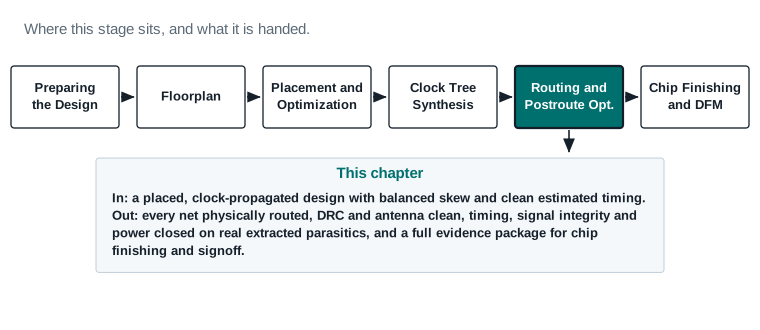
Concretely, by the end of this chapter you will be able to do seven things. You will confirm that a design is actually ready to begin routing, not just placed. You will choose and set the routing rules a design needs before the first routing command runs. You will walk the standard routing sequence — global routing, track assignment, detail routing, search-and-repair — and know what each stage is doing physically. You will recognize when a net or group of nets needs a custom-router path instead of the standard flow, run that path correctly, and verify its result before trusting it. You will perform postroute optimization as a measured, evidence-driven process rather than blind command repetition. You will read the reports that tell you whether routing is healthy. And you will work through a full stage-exit checklist, so you can hand a clean, evidence-backed design to chip finishing and signoff.
As with every chapter in this guide, the goal is not memorizing flags. It is building the same judgment a routing engineer uses every day. Does this design's physical wiring meet its design-rule, timing, signal-integrity and power targets? If it does not, which report tells you why? And which specific action actually fixes it?
| What enters this stage | What must leave it |
|---|---|
| A design with every clock tree built, routed, and marked propagated, meeting its CTS design-rule constraints (the Clock Tree Synthesis exit gate). | Every signal, clock, and special net fully and legally routed, with zero unintended unrouted nets, opens, or shorts. |
| Power and ground nets already prerouted and undisturbed by routing. | Routing design-rule violations and antenna violations at zero, or each remaining item explicitly reviewed and dispositioned. |
Clean, healthy clock latency and skew, verified in Clock Tree Synthesis with report_clock_qor. | Timing, transition, capacitance, crosstalk, and noise measured against routed parasitics — not estimates — and accepted in every required scenario. |
| Active scenarios, routing layers, and nondefault routing rule assignments (for critical, clock, and special nets) fully specified. | A saved checkpoint of the fully routed, postroute-optimized block, plus the reports that prove it, so the next stage starts from documented evidence. |
Estimated route versus physically completed route
Every stage before this one has already been giving you numbers that look like routing results — wire delay estimates, parasitic estimates, even a rough congestion map. Those are all built from an estimated route: a fast, approximate model of what the wiring will probably look like, good enough to guide placement and CTS decisions, but not physically real. Nothing has been checked against manufacturing design rules. No via has actually been chosen. No layer assignment has actually been made.
A physically completed route is different in kind, not just in accuracy. Every wire segment has a real layer, a real width, a real set of endpoints, and a real relationship to every neighboring shape on the same and adjacent layers. Every via is a real via, drawn from a real via definition, checked against enclosure and spacing rules. This is the geometry that a foundry could actually build. The difference matters for one reason. A routed net's parasitic resistance and capacitance can only be measured accurately once the route is physically real, and those parasitics set its timing, its crosstalk behavior and its power. That is why postroute optimization exists as its own disciplined step, covered in full in Part 7: the numbers change once estimation is replaced with reality, and someone has to close the gap.
Why routing is not simply “connecting every net”
A beginner's first mental model of routing is usually: draw a wire from each driver to each of its receivers. That mental model is not wrong, but it badly understates the problem. Every wire drawn has to share a small number of metal layers with tens of thousands of other wires, all competing for the same limited routing tracks. Every wire has to obey minimum width and spacing rules that exist so the chip can actually be manufactured without shorts or opens. Every wire adds resistance and capacitance, which changes the timing of the signal it carries. Every wire also couples electrically with its neighbors, in a way that can corrupt a neighboring signal's timing too. Every wire on certain layers, left connected to a transistor gate through an unfinished processing step, can accumulate enough charge during fabrication to damage that gate — the antenna effect, covered in Part 2. Routing is the stage that has to satisfy all of these constraints at once, for every net, across the whole design. Postroute optimization is the stage that proves the result is actually good, and fixes what is not.
What “route complete” means — and what it does not mean
A tool will happily report 100% routed once every net has a complete, connected physical path from driver to every receiver. That is a real and necessary milestone, and this chapter treats it as one. But route completion only means connectivity exists. It says nothing about whether that connectivity is legal, meaning design-rule clean. It says nothing about whether the result is safe to fabricate (antenna clean), fast enough (timing clean), quiet enough (crosstalk and noise clean), or affordable in power. A design can be 100% routed and still be nowhere near ready to leave this stage. Treat “route complete” as the halfway point of this chapter, not the finish line. The finish line is the Part 12 stage-exit checklist, and it checks all of the above.
How routing relates to timing, signal integrity, power, reliability, and manufacturability
These five concerns are not separate checklists you work through one at a time — they interact, often in tension with each other, and most of this chapter's engineering judgment lives in that tension.
- Timing. Routed wire resistance and capacitance directly set signal delay. A net routed on a slow, resistive lower layer arrives later than the same net routed on a faster upper layer. Routing choices made for congestion or manufacturability reasons can quietly cost timing margin. Evidence: report_timing, report_clock_qor, and setup/hold slack after parasitic extraction (Part 8).
- Signal integrity. Two wires running close together on adjacent tracks or layers couple electrically. A quiet neighbor switching at the wrong moment can add delay (crosstalk delay) or inject a glitch (noise) onto a victim net. Evidence: crosstalk delay and noise reports (Part 8).
- Power. Wire capacitance is a direct contributor to dynamic power. Wider, more heavily shielded, or more heavily buffered nets cost more power even when they help timing or signal integrity. Evidence: power reports before and after postroute optimization (Part 7, Part 8).
- Reliability. Certain routing choices — a long wire on a single unfinished-processing layer connected to a sensitive gate, or a via stack with no redundancy — create long-term or manufacturing-time reliability risk, not just a functional bug. Evidence: antenna reports, redundant-via coverage reports (Part 8).
- Manufacturability. Every shape has to obey the foundry's design rules — minimum width, minimum spacing, via enclosure — or the chip cannot reliably be built at all, independent of whether the logic would have worked. Evidence: routing DRC reports (Part 8).
A design that wins on one of these at the expense of the others is not done. A design that is DRC-clean but fails timing is not done. A design that meets timing by ignoring a crosstalk violation on a sensitive net is not done, even though its static timing report looks clean. Part 12's stage-exit checklist exists specifically so none of these five gets silently dropped while you are focused on the others.
| Entry checklist (must already be true) | Exit checklist (must be true to leave) |
|---|---|
| Legal placement, no overlaps, no fixed-cell violations | 100% routed, zero unintended unrouted nets |
| All clock trees built, routed, propagated, CTS DRC clean | Connectivity clean: zero opens, zero shorts |
| Power/ground routing complete and undisturbed | Routing DRC clean or explicitly dispositioned |
| Routing layers, rules, and blockages defined | Antenna clean or explicitly dispositioned |
| Congestion estimate acceptable, no unresolved overflow hot spots | Timing, transition, capacitance accepted on routed parasitics |
| Saved pre-route checkpoint | Crosstalk delay and noise accepted; power accepted; final checkpoint saved |
After this chapter, you will be able to
- Verify a design is genuinely ready for routing, using a full readiness checklist rather than assuming placement completion is enough.
- Choose routing layers, rules, and strategy based on the specific timing, congestion, and signal-integrity risk profile of a design.
- Run the standard routing sequence — global routing, track assignment, detail routing, search-and-repair — and correctly interpret each stage's evidence.
- Recognize when a net or net group needs the custom-router path, run it correctly, and verify its output before accepting it into the flow.
- Perform postroute optimization as a targeted, report-driven repair process for setup, hold, transition, capacitance, and crosstalk problems.
- Read the reports that describe routed geometry, congestion, timing, signal integrity, and power, and know which fields to check first.
- Diagnose common routing and postroute failures using decision trees instead of guessing.
- Work through a full stage-exit checklist and decide, with report evidence, whether a design is ready for chip finishing and signoff.
The mental model, before any commands
Before touching a single routing command, build the picture in your head. A chip's metal stack is a small number of layers — typically ten to fifteen in a modern process — stacked directly above the transistors, each layer reserved almost entirely for wiring in one preferred direction. Routing is the process of deciding, for every single net, exactly which layers, which tracks and which vias it will use to get from its driver to every one of its receivers. It has to do that without breaking a manufacturing rule, and without an unacceptable electrical side effect.
Routing layers and preferred direction
A routing layer is one metal layer of the process stack available for wiring. Each routing layer has a preferred routing direction — horizontal or vertical — alternating from one layer to the next. This exists because a via connecting two layers is smallest and most reliable when the two wires it joins run perpendicular to each other. Alternating direction by layer lets almost every via connect a horizontal segment to a vertical one cleanly. Lower layers (closer to the transistors) are typically thinner, more resistive, and more tightly spaced, used for short local connections and standard-cell pin access. Upper layers are thicker, faster, more expensive in area, and reserved for long nets, clock nets, and power distribution.
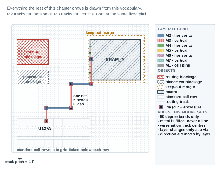
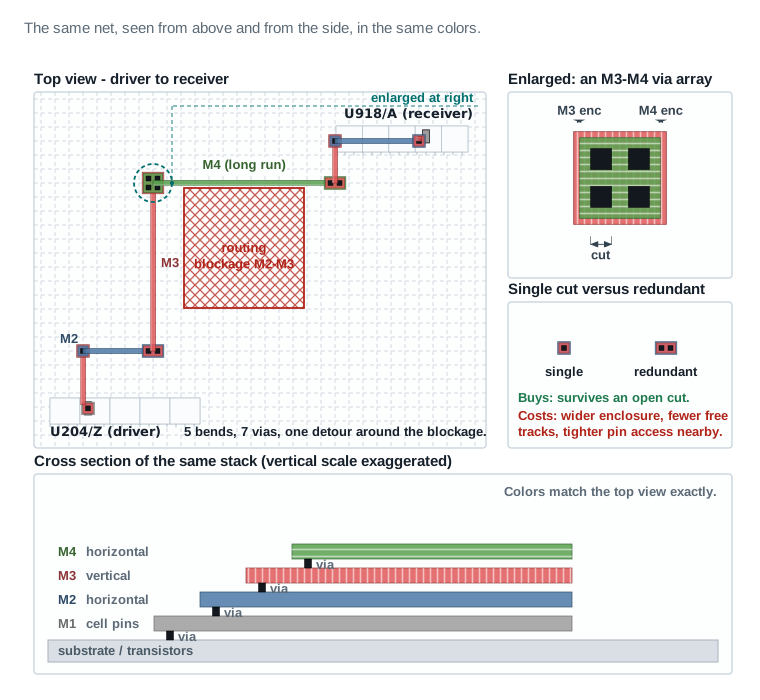
1 P. Metal is always a filled shape with a real width, never a thin line. The single net runs from the standard-cell M1 pin U12/A up to a macro edge pin as a staircase: it turns only at 90°, and every time it changes direction it changes layer, which means a via. The three blocked regions are deliberately drawn differently from one another — a routing blockage, a placement blockage and a keep-out margin are three different instructions to three different tools, and the legend keeps them apart.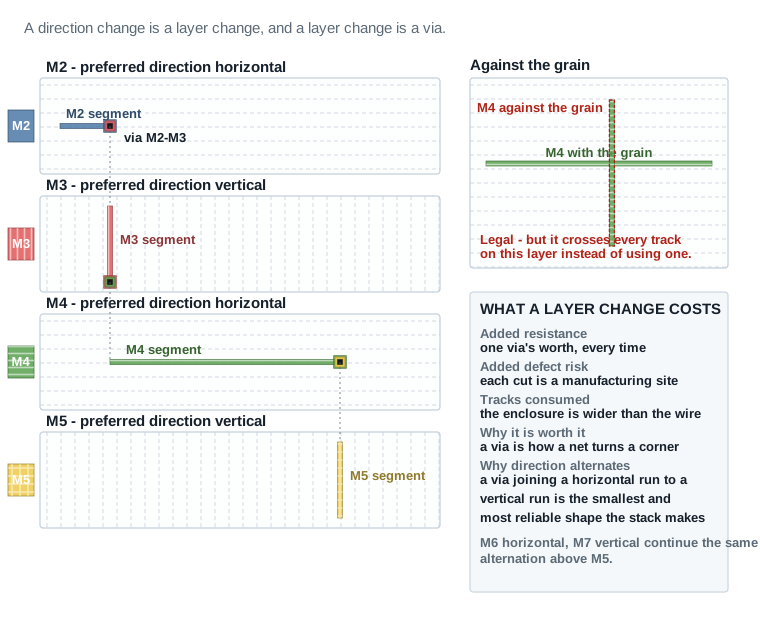
Wires, segments, shapes, pins, ports, terminals, and nets
A net is a single electrical connection: one driver pin and one or more receiver pins that must all be tied together. A net is not itself a piece of geometry — it is the electrical intent that routing must satisfy. A wire is one continuous run of metal on one layer connecting two points of a net. A long or bent wire is usually stored as multiple segments, each a straight run on a single layer between two coordinates. A shape is the general term for any piece of physical geometry — a wire segment, a via, a pin shape — on a layer. A pin is the physical location on a cell or macro where a net's driver or receiver connects; a port is the equivalent at the chip or block boundary. A terminal is the general term covering both. Routing's job, stated precisely, is: for every net, connect its driver terminal to every receiver terminal using a legal, connected set of wire segments and vias.
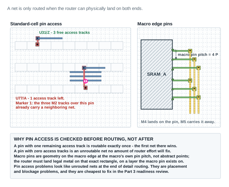
U31/Z has three free tracks over its M1 pin and is easy to reach. U77/A does not: three of the M2 tracks above it already carry a neighbor's net, so exactly one access track remains, and the marker says so. On the right, a macro's pins are real rectangles on the macro edge at the macro's own pin pitch, not abstract points — M4 lands on the pin because M4 is a layer the pin exists on, and M5 carries the net away in the perpendicular direction.Spacing rules, width rules, and nondefault routing rules
A spacing rule is the process technology's minimum allowed distance between two shapes on the same layer, set so the shapes can reliably be manufactured without shorting together. A width rule is the minimum (and sometimes maximum) allowed width of a shape on a given layer. Together these are the most basic routing design rules, and every wire the router draws, by default, uses the technology's standard minimum width and spacing. A nondefault routing rule (NDR) is a named, engineer-defined override of these defaults for specific nets. It typically asks for wider width, which lowers resistance and suits timing-critical or high-current nets. It can also ask for wider spacing, which lowers coupling capacitance and suits noise-sensitive nets. Many NDRs ask for both. NDRs are assigned deliberately, net by net or net-group by net-group, covered in Part 4.
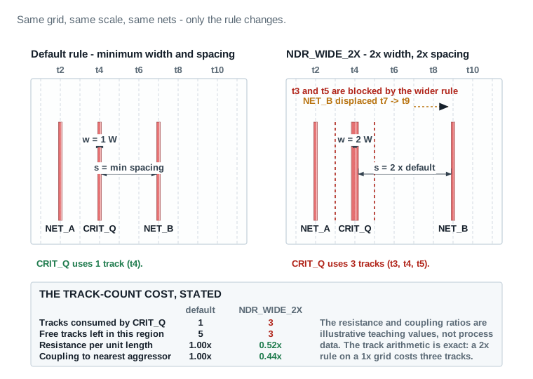
CRIT_Q is a default-width wire on one track. On the right it carries NDR_WIDE_2X: the metal is twice as wide and the spacing to each neighbor is twice as large, so the tracks either side of it (t3 and t5) can no longer be used by anything else, and NET_B has to move from t7 to t9. One net on a 2× rule costs three tracks, not two — that arithmetic is exact, and it is the real reason an NDR is assigned deliberately, net by net, instead of broadly.Vias and via stacks
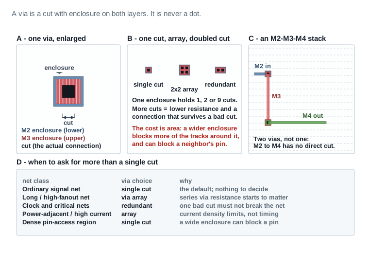
A via is the small vertical connection that joins a shape on one metal layer to a shape on the layer directly above or below it. A single via only connects two adjacent layers. To move a signal from, say, layer M2 to layer M5, routing must build a via stack. That is a sequence of vias through every intermediate layer (M2–M3, M3–M4, M4–M5), each with its own small connecting shape on the layers in between. Vias are one of the most common sources of resistance and reliability risk in a routed net. Each one adds resistance, and each one is a potential manufacturing defect site. That is why critical or high-current nets are often given redundant vias: two vias in parallel at the same layer transition, so that a single via defect does not break the connection.
Net categories: signal, clock, power, special, and critical
Routing does not treat every net the same way. A signal net is an ordinary logic connection between two or more cells. A clock net was already built in Clock Tree Synthesis. Entering this stage it is either already routed, if clock_opt included route_clock, or it still needs its final detail routing pass. That pass usually runs on reserved layers with nondefault rules, to protect skew. A power net (including ground) was prerouted before placement and must not be disturbed by signal routing. Routing treats existing power geometry as a fixed obstruction. A special net is any net that needs handling outside the ordinary automatic flow — a reset tree, a scan chain, an analog-adjacent net, or anything assigned a nondefault routing rule. A critical net is any net — timing-critical, noise-sensitive, or high-current — that the engineer has deliberately flagged for special treatment, such as wider width, extra spacing, or shielding, covered later in this Part and in Part 4.
Global routing versus detail routing
Global routing divides the design into a coarse grid of rectangular regions, the global routing cells or GCells. For every net it then decides which sequence of GCells that net will pass through, and roughly which layers it will use. It does not yet draw exact wire geometry. It is a planning step: fast, approximate, and essential for predicting where routing resources will run short before committing to exact wires. Detail routing is the step that takes global routing's plan and converts it into exact, legal, design-rule-correct wire segments and vias, track by track, inside each GCell. Global routing without detail routing is only a plan. Detail routing without a global routing plan first would be far too slow. It would have to search the entire design's resources for every net, instead of working from a good starting plan.
Routing tracks and track assignment
A routing track is one of the evenly spaced lines, on a given layer, along which a wire is permitted to run in that layer's preferred direction. Track spacing is fixed by the process technology. Track assignment is the step between global and detail routing that assigns each net's global-routing path to specific tracks, resolving track-level conflicts between nets before the slower, more exact detail-routing step has to.
Route guides
A route guide is a region, on a specific layer or a range of layers, that the engineer or the tool uses to steer a net's routing. It forces the net to stay inside a given area, or to keep out of one. Route guides are most often used for critical nets that need a predictable path for timing or signal-integrity reasons, or to keep a net off a layer or region reserved for something else.
Congestion, capacity, overflow, hot spots, and detours
Routing capacity is the number of tracks actually available to route through a given region, on a given layer, after subtracting space used by blockages, pins, and already-committed geometry such as power routing. Routing demand is how many tracks the nets that need to pass through that region actually want. Congestion is the relationship between the two: a region is congested when demand approaches or exceeds capacity. Overflow is the specific, measurable amount by which demand exceeds capacity in a region — the number of nets that could not be assigned a track there. A hot spot is a region with persistent, significant overflow that resists an ordinary routing pass. A detour is the direct, physical consequence of congestion. A net that cannot get a track along its shortest path is routed the long way around. That adds wire length, resistance, capacitance and delay it would not otherwise have had.
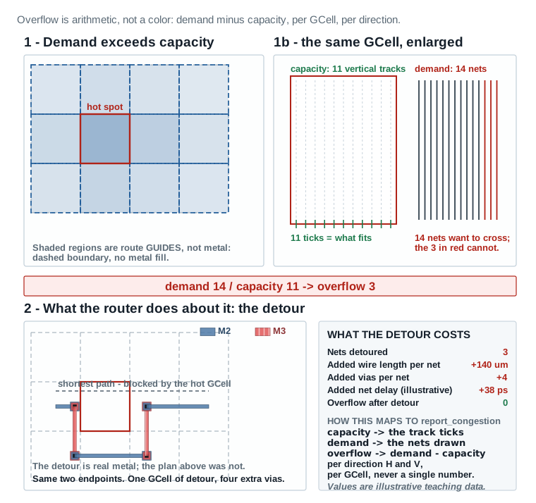
Wire length, resistance, and capacitance
Every routed wire segment has physical resistance (which slows the signal edge and adds delay along the wire) and capacitance (both to the substrate/plane below, and to neighboring wires — coupling capacitance, covered next). Longer wires, and wires on thinner/more resistive lower layers, have more resistance and more delay per unit length. Wire length is therefore not just a cosmetic or area metric. It is a direct, physical driver of timing and power. That is why a detour forced by congestion is a real engineering cost, not just an inconvenience.
Coupling capacitance, crosstalk, crosstalk delay, and noise
Coupling capacitance is the capacitance between two physically adjacent wires on the same or nearby layers. It exists because any two conductors close together form a small capacitor, whether anyone wanted them to or not. Crosstalk is the general term for the electrical interaction this causes between an aggressor net (the one switching) and a victim net (the one being disturbed). It shows up two ways. The first is crosstalk delay: a victim's signal arrives earlier or later than it would in isolation, because a nearby aggressor happened to switch at the same time. The second is noise: a victim that is supposed to be electrically quiet momentarily glitches because of an aggressor's switching, and that glitch can be mistaken for a real logic transition. Both are covered as their own analysis and repair topics in Parts 7 and 8.
Shielding
Shielding is the practice of routing a dedicated grounded or power-tied wire directly alongside a sensitive net, on one or both sides. It does two things at once. It reduces coupling capacitance to real aggressors, and it gives any coupled noise a low-impedance path to a stable rail instead of into the victim's own signal. Shielding costs routing resources, because the shield wire occupies a track that could otherwise carry a signal. So it is applied selectively, to nets that are timing-critical, noise-sensitive, or both.
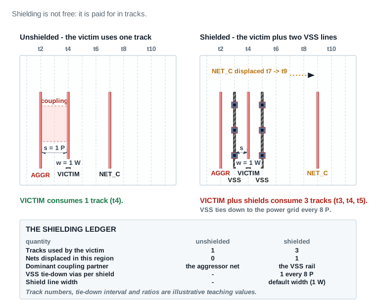
Layer constraints, via constraints, and blockages
A layer constraint restricts which layers a net, or a whole class of nets, is permitted to use. You might keep a clock net off the very lowest layers to protect skew, or keep a sensitive analog-adjacent net off a layer that carries a noisy digital bus. A via constraint restricts which via definitions, or how many via layers, a net may use. A high-current power-adjacent net might be required to use redundant vias, for instance. A blockage is a region marked off-limits (fully or on specific layers) to routing, typically to reserve space for macro keep-outs, future ECO headroom, or manufacturing-sensitive regions.
Antenna effects
During fabrication, a long metal wire that is connected to a transistor gate but not yet connected to its final protective diode or driver can act like an antenna, collecting stray charge from plasma-based manufacturing processes. If enough charge accumulates on a wire connected only to a gate, it can discharge through that thin gate oxide. It permanently damages the transistor, long before the chip is ever powered on for real use. This is the antenna effect. It is purely a function of routed wire area and layer, not of the design's logic, which is why it is checked and fixed as part of routing rather than in earlier, less-physical stages.
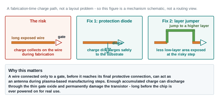
Design-rule violations, opens, shorts, and connectivity errors
A design-rule violation (DRV), in the routing context, is any piece of geometry that breaks a manufacturing rule — too close to its neighbor, too narrow, an illegal via enclosure. An open is a net that is supposed to be one electrically connected piece of copper but, due to a routing or extraction problem, is actually broken into two or more disconnected pieces. A short is the opposite failure: two different nets that are supposed to be electrically separate are, due to a routing error, physically touching or overlapping. Both opens and shorts are connectivity errors and are always unacceptable — unlike some DRC or antenna items, there is no such thing as an acceptable, dispositioned open or short.
Parasitic extraction, estimated versus routed timing, and ECOs
Parasitic extraction is the process of measuring the actual resistance and capacitance of every routed shape, from the real physical geometry, rather than estimating it. Timing computed from extracted, routed parasitics is simply more trustworthy than timing computed from any earlier estimate, because it reflects what was actually built rather than a prediction. An engineering change order (ECO) is any small, targeted, after-the-fact change to a design that is already mostly finished. A cell resize, a buffer insertion or a local reroute all count. What makes it an ECO is that the change is made surgically, instead of by rerunning the whole flow. A route ECO is specifically a targeted rerouting of one net or a small group of nets. It is most often used to clean up the local consequences of a postroute optimization change (Part 7) or a custom-router import (Part 6).
Postroute optimization, in one sentence
Postroute optimization is the process of using the real, routed, extracted parasitics to find and fix problems. Those are the timing, transition, capacitance, crosstalk and power problems that only became visible once the route was physically real. Part 7 covers it in full. It exists because no estimate, however good, is a substitute for measuring the real thing.
Beginner vocabulary quick reference
- GCell (global routing cell)
- A coarse rectangular region used by global routing to plan net paths before exact geometry is drawn.
- Preferred direction
- The horizontal or vertical direction a given routing layer is optimized for; alternates layer to layer.
- Track
- One of a layer's evenly spaced, technology-fixed lines a wire may run along in the preferred direction.
- Via
- A vertical connection between two adjacent metal layers.
- Via stack
- A sequence of vias connecting non-adjacent layers through every layer in between.
- Redundant via
- A second, parallel via at the same layer transition, added for reliability.
- Overflow
- The measurable amount by which routing demand exceeds capacity in a region.
- Detour
- Extra wire length a net accumulates when it cannot use its shortest path due to congestion or blockages.
- Coupling capacitance
- Capacitance between two physically adjacent wires, the physical basis of crosstalk.
- Aggressor / victim
- The switching net causing crosstalk (aggressor) and the net being disturbed by it (victim).
- Nondefault routing rule (NDR)
- An engineer-defined override of default width and/or spacing for specific nets.
- Antenna effect
- Fabrication-time gate damage risk from charge accumulated on a long wire connected only to a gate.
- DRV
- Design-rule violation: any geometry that breaks a manufacturing spacing, width, or via rule.
- Parasitic extraction
- Measuring the real resistance and capacitance of routed geometry, as opposed to estimating it.
- Route ECO
- A small, targeted reroute of one net or a small net group, done without rerunning the full flow.
Is this design actually ready to route?
Routing is expensive to redo. A design that starts routing before it is genuinely ready wastes runtime. Worse, it can bury a real problem — illegal placement, unresolved congestion, a missing scenario — under a mountain of routed geometry that then has to be unwound. This Part is a disciplined readiness review, item by item, each ending in a PASS, REVIEW, or BLOCKER classification. Do not begin routing in the worked example (Part 10) until every item below has an explicit classification.
Picture the design exactly as it sits right now. Cells are legalized on their rows, a clock tree is already built and propagated, and not one signal wire has been drawn. This Part is the walk-around you do before that first wire goes down, the way you would walk a building site before anyone pours concrete.
Command verification noteThe names check_legality, check_pg_connectivity, check_mv_design, check_routability and get_scenarios are used in this Part's readiness checks, and all five are independently verified against the real Synopsys ICC2 Tcl Command Reference. Three others remain this chapter's illustrative pseudocode: check_pin_access, check_connectivity and report_layer_usage. No command by those names was found in that reference. See qa/command-verification.csv for the full, per-command status.
Placement and clock readiness | |
Readiness item 1 Placement legality
|
Readiness item 2 Completed clock tree synthesis and clock routing status
|
Readiness item 3 Power and ground routing
|
|
Timing, congestion, and rule readiness | |
Readiness item 4 Required scenarios and corners defined
|
Readiness item 5 Timing state entering routing
|
Readiness item 6 Congestion state
|
Readiness item 7 Design-rule constraints and layer availability
|
Blockage, pin, and special-net readiness | |
Readiness item 8 Blockages, keepouts, and routing obstructions
|
Readiness item 9 Pin accessibility and macro interfaces
|
Readiness item 10 High-fanout nets and their routing plan
|
Readiness item 11 Routing-rule assignments and special-net status
|
Readiness item 12 Multivoltage considerations, where applicable
|
Readiness item 13 Saved checkpoint and recovery point
|
Readiness item 14 Required reports and baseline evidence
|
|
Readiness checklist summary
The fourteen teaching cards above explain why each gate exists. This board is the summary you come back to: every gate, its evidence, its threshold, its status, and what to do about it, on one page.
| Gate | What to check | Evidence (Nimbus‑8 u_sens_tile) | Threshold | Status | Required action |
|---|---|---|---|---|---|
| 1. Placement legality | Every cell legal, on-site, no overlaps | check_legality: 0 violations | 0 violations | PASS | — |
| 2. CTS complete, clocks propagated | Clock tree built and routed or scheduled for clock routing | report_clock_qor: 52 ps global / 18 ps local skew, 0 clock DRC | ≤100 ps global, ≤30 ps local, 0 DRC | PASS | — |
| 3. Power and ground routing complete | PG mesh committed; signal routing must treat it as fixed | check_pg_connectivity: clean | 0 unconnected PG pins | PASS | — |
| 4. Required scenarios active | Every scenario routing must close against is on | get_scenarios: func_ss_0p72v_125c, func_ff_0p88v_m40c, test_ss_0p72v_125c | Setup and hold corners both active | PASS | — |
| 5. Timing state entering routing | Estimated timing healthy before wires are real | WNS(setup) +0.031 ns, WNS(hold) +0.045 ns | Both ≥0 on the estimate | PASS | — |
| 6. Congestion state | Global-route overflow low enough to detail-route | Overflow 0.6% H / 0.3% V; one hot spot beside the planned ADC-bus region | <1% H and V, no persistent hot spot | REVIEW | Resolve the hot spot before routing. Resolved by the Part 10 Step 2 custom-router carve-out; re-classified PASS. |
| 7. Design-rule constraints and layer availability | Layer range and reservations set deliberately | M2–M9 available; M6/M7 reserved for the ADC bus | Stated, not inherited by accident | PASS | — |
| 8. Blockages, keepouts, obstructions | Routing obstructions match the floorplan intent | Matches floorplan; ADC-bus keep-clear confirmed | No unexplained blockage | PASS | — |
| 9. Pin accessibility, macro interfaces | Every pin has at least one legal access track | check_pin_access: 0 unreachable pins | 0 unreachable | PASS | — |
| 10. High-fanout net plan | Reset/scan/enable trees already buffered or planned | Scan-enable and reset trees pre-buffered in Placement and Optimization | No unbuffered high-fanout net entering routing | PASS | — |
| 11. Routing-rule and special-net assignment | NDRs, shielding and special nets named before routing | 42 timing-critical nets on NDR_WIDE_2X; sens_adc_in[15:0] flagged for the custom router | Every special net named and assigned | PASS | — |
| 12. Multivoltage considerations | Domain crossings and level shifters legal, where applicable | Single-voltage partition — check_mv_design not applicable | Clean, or explicitly not applicable | PASS | — |
| 13. Saved checkpoint and recovery point | A reopenable pre-route state exists | nimbus8_sens_tile_pre_route_v1, reopen verified | Checkpoint exists and reopens | PASS | — |
| 14. Required reports and baseline evidence | Baselines saved so postroute change can be measured | Timing, congestion and clock-QoR baselines saved | All three baselines on disk | PASS | — |
Readiness verdict for u_sens_tile: 13 PASS, 1 REVIEW resolved in Part 10 Step 2 → GO to routing.
Read it: Read down the Status column first. Thirteen gates are PASS and one — gate 6, congestion — is REVIEW, which means routing does not start until it is resolved or consciously accepted. The Required action column is not decoration: a REVIEW with no stated action is the same as an unresolved BLOCKER. Gate 6's action was carried out in Part 10 Step 2 and the gate was then re-classified PASS, with the carve-out decision itself as the evidence.
Field values in the Evidence column are this chapter's illustrative teaching data, not a real tool transcript.
Part 10 walks through this exact checklist against the Nimbus‑8 project, with real evidence and a real PASS/REVIEW/BLOCKER classification on every row. This Part defines what to check and why. Part 10 shows it done.
Choosing a routing strategy before you route
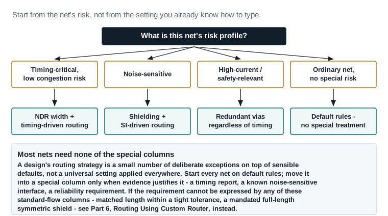
Every routing setting below exists to solve a specific engineering problem — not as an item on an alphabetical options list. This Part is organized by the problem each group of settings addresses, so you can reason from “what am I worried about in this design” to “which setting addresses that,” the way an engineer actually works.
Think of this Part as setting the rules of the road before any traffic moves. Nothing here draws metal. Every setting you make now decides how the router behaves later, when there are tens of thousands of wires and no time to supervise any one of them.
Problem: which layers should carry which kind of net
set_ignored_layers / preferred and restricted layers
Decide, before routing, which layers each category of net is allowed to use.
- Problem it addressesWithout an explicit layer plan, the router is free to use any available layer for any net, which can put clock, power-adjacent, or noise-sensitive nets on layers you would not have chosen.
- Default behaviorAll routing layers are available to all signal nets by default; clock and power nets already carry layer intent from earlier stages.
- Exact action
icc2_shell> set_ignored_layers -min_routing_layer M2 -max_routing_layer M9
- When to change itWhen specific layers should be reserved for clock, power-adjacent shielding, or kept clear for known manufacturing sensitivity.
- When not to change itFor a design with no special layer sensitivity, default layer availability is usually fine and adding restrictions only reduces routing resource for no benefit.
- Expected benefitPredictable, intentional layer usage for the nets that matter most.
- Possible side effectRestricting layers reduces available routing resource and can increase congestion elsewhere if applied too broadly.
- Evidence used to verify it
report_layer_usageafter routing, checked against the intended plan.
Problem: critical-net and clock-net treatment
Assigning nondefault routing rules by net criticality
Give timing-critical, noise-sensitive, or high-current nets wider width and/or spacing than the default.
- Problem it addressesDefault-rule routing treats every net identically, which is wrong for the small fraction of nets that are genuinely timing- or noise-critical.
- Default behaviorEvery net routes at the technology's default minimum width and spacing unless assigned otherwise.
- Exact action
icc2_shell> create_routing_rule NDR_WIDE_2X -widths {M4 0.2 M5 0.2} -spacings {M4 0.2 M5 0.2}
icc2_shell> set_routing_rule -rule NDR_WIDE_2X [get_nets CRIT_*]
- When to change itFor the top setup-critical nets flagged by timing analysis, or nets already flagged noise-sensitive from architecture knowledge.
- When not to change itFor the vast majority of ordinary signal nets — applying NDR broadly consumes routing resource without a matching benefit and can worsen congestion.
- Expected benefitLower resistance (timing) and/or lower coupling capacitance (noise) on the specific nets that need it.
- Possible side effectIncreased local congestion around NDR nets, and increased capacitance if width is increased without a matching need.
- Evidence used to verify it
report_timingand crosstalk reports on the assigned nets after routing (Part 8).
Problem: via reliability on critical or high-current paths
Redundant via insertion policy
Decide which nets receive a second, parallel via at each layer transition.
- Problem it addressesA single via is a single point of manufacturing-defect failure; on a critical or high-current net that risk is worth removing.
- Default behaviorDetail routing inserts single vias by default unless a redundant-via policy is set.
- Conceptual workflow exampleConceptual workflow exampleYou would enable redundant-via insertion on the flagged critical nets (a call resembling
set_redundant_via_rule, naming the net collection and turning the rule on). - When to change itTiming-critical nets, clock nets, and any high-current signal path.
- When not to change itApplying it everywhere costs routing resource for negligible benefit on ordinary low-risk nets.
- Expected benefitLower via resistance and lower single-point manufacturing-defect risk.
- Possible side effectExtra via area can tighten local routing resource near dense via regions.
- Evidence used to verify itRedundant-via coverage report after detail routing (Part 8).
Problem: congestion risk known ahead of routing
Congestion-driven setup: blockage relief and route guides
Address a known congestion risk before it becomes a hot spot during detail routing.
- Problem it addressesA congestion estimate (Part 3, Readiness item 6) identified regions where demand is close to or over capacity.
- Default behaviorThe router resolves ordinary congestion on its own during global routing; severe, structural congestion usually needs help.
- Conceptual workflow exampleConceptual workflow exampleYou would define a route guide over the congested region. That guide is a named zone with an explicit layer range and a rectangular boundary, and it steers signal routing away from the area under pressure. The call resembles
create_route_guide, naming the guide, its layers and its boundary coordinates. - When to change itWhen a congestion estimate flags a persistent hot spot before routing, or the same region flagged repeatedly in earlier stages.
- When not to change itFor a design with clean congestion estimates — adding guides without evidence adds routing complexity for no benefit.
- Expected benefitFewer detours, fewer unresolved DRC violations in the flagged region.
- Possible side effectAn overly restrictive guide can push congestion to an adjacent region instead of resolving it.
- Evidence used to verify it
report_congestionre-run after global routing, comparing the flagged region before and after.
Problem: timing-critical paths need routing-aware protection
Timing-driven routing setup
Let detail routing weigh a net's timing criticality when resolving track conflicts.
- Problem it addressesWithout timing awareness, track-assignment conflicts are resolved arbitrarily, which can detour a timing-critical net around a hot spot instead of a less-critical one.
- Default behaviorTiming-driven routing is available but must be explicitly enabled for a strongly timing-driven strategy.
- Conceptual workflow exampleConceptual workflow exampleYou would switch the router's optimization strategy to prioritize timing, at high effort (a call resembling
set_route_opt_strategywith a timing-driven flag and an effort level). - When to change itAny design with meaningful setup criticality remaining entering routing.
- When not to change itRarely turned off entirely; high effort is sometimes reduced to medium on a design with generous timing margin, to save runtime.
- Expected benefitCritical nets preferentially get shorter, less-detoured paths.
- Possible side effectHigher effort increases routing runtime.
- Evidence used to verify itSetup slack comparison between a timing-driven and non-timing-driven trial, or against the pre-route baseline.
Problem: signal integrity risk on dense or high-fanout regions
Signal-integrity-driven routing setup
Let routing account for expected crosstalk risk while placing tracks, not just after the fact.
- Problem it addressesDense parallel-routed regions create coupling risk that is cheaper to avoid during routing than to repair afterward.
- Default behaviorSI-aware routing is available but not always enabled by default at every effort level.
- Conceptual workflow exampleConceptual workflow exampleYou would switch the router's optimization strategy to prioritize signal integrity (a call resembling
set_route_opt_strategywith a signal-integrity-driven flag). - When to change itDesigns with known noise-sensitive nets, high switching activity, or tight track pitch relative to signal frequency.
- When not to change itLow-risk designs with generous spacing margin can skip it to save runtime.
- Expected benefitFewer crosstalk delay and noise violations discovered in postroute analysis.
- Possible side effectIncreased routing runtime; occasionally slightly worse congestion as the router avoids otherwise-attractive parallel runs.
- Evidence used to verify itCrosstalk delay/noise violator counts before and after enabling it (Part 8).
Problem: antenna risk from long wires on early layers
Antenna prevention strategy
Reduce antenna violations proactively instead of fixing all of them after routing.
- Problem it addressesLong single-layer wires connected only to a gate risk fabrication-time gate damage (Part 2).
- Default behaviorDetail routing does not automatically avoid long single-layer runs unless antenna-aware routing is enabled.
- Conceptual workflow exampleConceptual workflow exampleYou would switch the router's optimization strategy to prioritize antenna-effect avoidance, then set the preferred antenna fix method. That is two calls. One resembles
set_route_opt_strategywith an antenna-driven flag; the other resemblesset_antenna_rule, naming diode and jumper as the acceptable fix techniques. - When to change itAlways worth enabling for antenna-aware routing; the fix-method choice depends on available diode cells and layer budget.
- When not to change itThe choice between diode-only and diode-plus-jumper fixing depends on library diode availability, not a “never use this” case.
- Expected benefitFewer antenna violations surfacing after routing, each of which is cheaper to prevent than to repair.
- Possible side effectDiode insertion adds cell area; layer jumpers consume via resource.
- Evidence used to verify itAntenna violation count after detail routing, before and after enabling (Part 8).
Problem: power-aware routing decisions
Power-aware routing considerations
Recognize where routing choices trade power against timing or signal integrity.
- Problem it addressesNDR width, shielding, and buffer-heavy repairs all increase capacitance and therefore dynamic power; an unmanaged strategy can win timing at an unacceptable power cost.
- Default behaviorRouting does not optimize for power directly; power is a consequence of width, shielding, and buffering choices made for other reasons.
- Exact action
icc2_shell> report_power -scenarios [all_scenarios] > power_pre_route.rpt
- When to change itApply NDR and shielding selectively (Part 4 above), not broadly, specifically to limit unnecessary power growth.
- When not to change itDo not withhold NDR/shielding from a genuinely critical net purely to save power — a timing or noise failure is not an acceptable trade for lower power.
- Expected benefitAwareness of the power cost of every SI/timing decision, so the total strategy stays balanced.
- Possible side effectNone on its own — this is a measurement habit, not a setting.
- Evidence used to verify itPower reports compared before and after every major routing/optimization step (Part 7, Part 8).
Problem: runtime versus quality, scenario selection, and incremental strategy
Effort level, scenario selection, and incremental versus full routing
Match routing effort and scope to what actually changed, instead of always running everything at maximum effort.
- Problem it addressesFull, maximum-effort routing on every iteration wastes runtime when only a small part of the design changed since the last routed checkpoint.
- Default behaviorA first routing pass on a fresh design is always full; later passes can be incremental.
- Exact action
icc2_shell> route_auto -reuse_existing_global_route true
- When to change itAfter a small ECO, a custom-router import (Part 6), or a targeted postroute repair (Part 7).
- When not to change itThe very first routing pass on a design, or after a change large enough that incremental routing cannot safely assume the rest of the design is unaffected.
- Expected benefitMuch faster turnaround on later iterations without re-solving already-good regions.
- Possible side effectIncremental routing can miss a global opportunity a full re-route would have found; periodically re-verify with a full pass.
- Evidence used to verify itCompare incremental-run wire length/congestion/timing against a periodic full-run baseline.
Checkpoint strategy
Save a named checkpoint after every major stage in Part 5's sequence — after global routing, after detail routing, after search-and-repair convergence, and after postroute optimization. Each checkpoint is a safe rollback point if a later step goes wrong, and each is also a source of the “before” evidence Part 8's analysis depends on. This habit costs disk space and a few minutes per save; it saves far more time the first time something needs to be re-diagnosed from a known-good point instead of from scratch.
The standard routing sequence, stage by stage
This is the normal path almost every net in almost every design takes. Part 6 covers the alternative path — the custom router — for the specific nets that need it; everything in this Part is the baseline every design starts from and returns to.
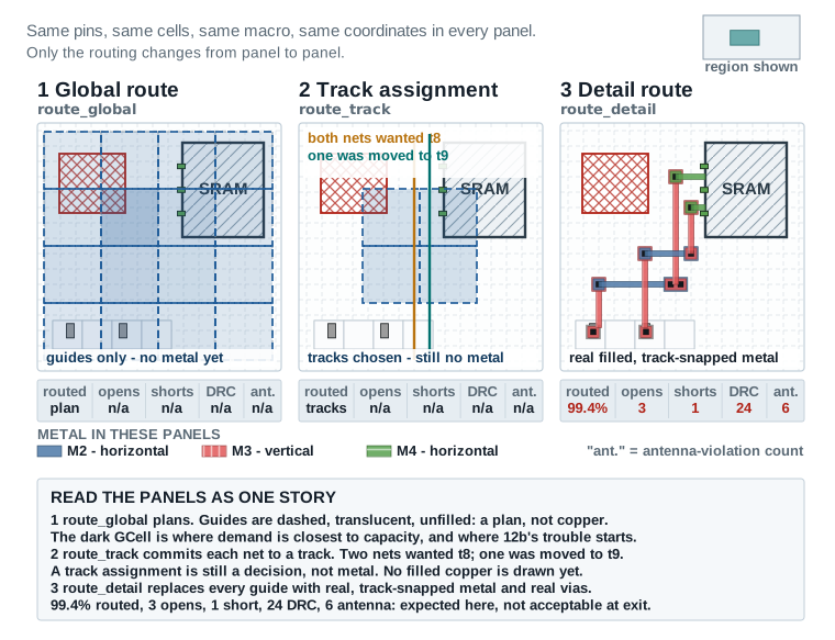
Picture the sequence as four passes over the same piece of the design, each one more committed than the last. First a plan of which regions each net crosses. Then a specific track for each net. Then real copper. Then repairs. Figures 12a and 12b show one identical region at each of those points, so you can watch the plan turn into metal.
check_routability / pre-route checks
Confirm the design is structurally ready to route before spending runtime on it.
- PurposeCatch structural problems — illegal placement, missing routing rules, unreachable pins — before committing runtime to routing.
- InputsThe placed, clock-propagated design from Part 3's readiness review.
- Exact action
icc2_shell> check_routability - Expected messagesA clean summary with zero blocking errors; warnings are reviewed, not ignored.
check_routability / pre-route checks — continued
Confirm the design is structurally ready to route before spending runtime on it.
- VerificationZero errors; any warnings traced back to a specific net or region and understood.
- Common failureUnreachable pins or illegal placements slipped past the Part 3 readiness review.
- RecoveryReturn to the specific readiness item that check_routability's message maps to (Part 3) before proceeding.
- Decision to continueProceed to global-route planning only once check_routability is clean.
route_global
Plan, per net, which GCells and roughly which layers it will use.
- PurposeProduce a fast, approximate routing plan for every net, so congestion and resource conflicts are visible before detail routing commits to exact geometry.
- Physical changes producedNone yet — global routing is a plan, not physical geometry.
- Exact action
icc2_shell> route_global -effort_level medium
- Expected messagesA global-routing summary reporting estimated wire length, via count, and overflow.
route_global — continued
Plan, per net, which GCells and roughly which layers it will use.
- Verification
report_congestionimmediately after, to see the global-routing-based congestion estimate. - Common failureSignificant overflow in one or more regions, signaling a resource problem that detail routing alone cannot fix.
- RecoveryReturn to Part 4's congestion-driven setup (route guides, blockage relief) or, if severe, back to placement.
- Decision to continueProceed to congestion estimation review before track assignment; do not skip straight to detail routing on a high-overflow result.
report_congestion
Decide, from the global-routing result, whether the design is ready to proceed to track assignment.
- PurposeGive the engineer a specific, region-by-region view of overflow before committing to detail routing.
- InputsThe global-routing plan from Stage 2.
- Exact action
icc2_shell> report_congestion -mode summary
- Expected messagesA GCell-by-GCell overflow list; a healthy design shows overflow near zero everywhere.
report_congestion — continued
Decide, from the global-routing result, whether the design is ready to proceed to track assignment.
- VerificationOverflow confined to small, explainable regions, or fully zero.
- Common failureA persistent hot spot in the same region flagged during Part 3 readiness — meaning the earlier relief attempt was insufficient.
- RecoveryApply stronger congestion relief (Part 4) and rerun global routing before proceeding; do not push a known hot spot into detail routing hoping it resolves itself.
- Decision to continueProceed to track assignment once overflow is acceptable; otherwise return to Stage 2.
route_track
Assign each net's global-routing path to specific tracks, resolving track-level conflicts before detail routing.
- PurposeReduce the search space detail routing has to solve, by resolving track-level assignment conflicts up front.
- Physical changes producedStill not final geometry, but each net now has a specific track plan within its global-routing path.
- Exact action
icc2_shell> route_track - Expected messagesA summary reporting the number of nets successfully assigned versus deferred to detail routing's own resolution.
route_track — continued
Assign each net's global-routing path to specific tracks, resolving track-level conflicts before detail routing.
- VerificationA low deferred-net count relative to total nets; a high count suggests unresolved congestion from Stage 3.
- Common failureA large number of deferred nets concentrated in one region, echoing an unresolved congestion hot spot.
- RecoveryReturn to Stage 3's congestion review; track assignment cannot fix a genuine resource shortage, only expose it more precisely.
- Decision to continueProceed to detail routing once track assignment converges with an acceptable deferred-net count.
route_detail
Convert the routing plan into exact, legal wire geometry and vias.
- PurposeProduce real, physically complete, design-rule-legal wiring for every net.
- Physical changes producedEvery net becomes real wire segments and via stacks, obeying width, spacing, and via rules on real layers.
- Exact action
icc2_shell> route_detail - Expected messagesA completion summary: percent routed, wire length, via count, and an initial DRC violation count.
route_detail — continued
Convert the routing plan into exact, legal wire geometry and vias.
- Verification
report_route_statusshows 100% routed, and an initial (not yet final) DRC count. - Common failureA small number of nets remain unrouted, usually in a congested or pin-access-limited region.
- RecoveryTrace each unrouted net's region back to Part 3 readiness or Stage 3 congestion; do not proceed with unrouted nets outstanding.
- Decision to continueProceed to search-and-repair once route status is 100%, even with a nonzero initial DRC count — that count is expected to drop in the next stage.
route_detail -max_number_iterations
Iteratively resolve the design-rule violations left after the first detail-routing pass.
- PurposeClean up the DRC violations that an initial detail-routing pass, working net by net, inevitably leaves behind where nets' geometry conflicts.
- Physical changes producedLocal rip-up and reroute of the specific shapes involved in each violation, not a full reroute.
- Exact action
icc2_shell> route_detail -max_number_iterations 6
- Expected messagesA violation count reported after each iteration, decreasing toward zero.
route_detail -max_number_iterations — continued
Iteratively resolve the design-rule violations left after the first detail-routing pass.
- VerificationViolation count reaches zero, or plateaus at a small, explainable, dispositioned residue.
- Common failureNonconvergence — the violation count stops decreasing, or oscillates, across iterations (see Part 9 for full diagnosis).
- RecoveryIdentify the specific region driving nonconvergence and address its root congestion or rule conflict rather than raising the iteration limit indefinitely.
- Decision to continueProceed to antenna handling and connectivity checking once DRC violations reach zero or an explicitly accepted residue.
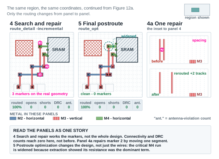
ant. is the antenna-violation count.route_detail -incremental true, check_routes
Fix antenna violations, then verify the routed design is electrically and geometrically sound.
- PurposeFix fabrication-time gate-damage risk, and confirm the routed geometry is both connected (no opens/shorts) and design-rule legal.
- Physical changes producedDiode insertion or layer-jumper fixes for antenna violations; no changes from the connectivity/DRC checks themselves, which are read-only.
- Exact action
icc2_shell> route_detail -incremental true
icc2_shell> check_routes
- Expected messagesAntenna violator count reaching zero; connectivity and DRC checks both reporting zero.
route_detail -incremental true, check_routes — continued
Fix antenna violations, then verify the routed design is electrically and geometrically sound.
- VerificationZero remaining antenna violations, zero opens, zero shorts, zero DRC violations, all confirmed by report, not assumed.
- Common failureA residual antenna violation on a net whose available diode sites are already exhausted locally.
- RecoveryUse a layer-jumper fix on the affected segment, or relocate a diode cell nearby if none is currently reachable.
- Decision to continueProceed to the timing update only once connectivity, DRC, and antenna are all clean or explicitly dispositioned.
extract_rc, update_timing
Replace estimated parasitics with real, extracted, routed parasitics, and re-run timing analysis against them.
- PurposeGive timing analysis the real numbers, since routed geometry now exists to measure.
- Physical changes producedNone — this stage measures the design, it does not change it.
- Conceptual workflow exampleConceptual workflow exampleYou would extract parasitics from the now-complete routed geometry, then update timing analysis with that real parasitic data (two calls resembling
extract_rcandupdate_timingwith a full-update flag). - Expected messagesAn extraction summary and a timing update confirmation across all active scenarios.
extract_rc, update_timing — continued
Replace estimated parasitics with real, extracted, routed parasitics, and re-run timing analysis against them.
- VerificationCompare the new, routed-parasitic timing against the Part 3 pre-route baseline; some regression here is expected and normal.
- Common failureA larger-than-expected timing regression, suggesting the routed geometry took a much less favorable path than the estimate predicted.
- RecoveryTrace the largest regressions back to specific nets (Part 8) and address them in postroute optimization (Part 7) rather than assuming they will self-correct.
- Decision to continueProceed to postroute optimization (Part 7) with this update as its starting evidence.
save_block, and the go/no-go decision
Save the routed checkpoint and decide, from evidence, whether to proceed forward or return to an earlier stage.
- PurposePreserve this exact state before postroute optimization begins changing it, and make an explicit forward/back decision rather than proceeding by default.
- Physical changes producedNone — a checkpoint save does not alter the design.
- Exact action
icc2_shell> save_block -as nimbus8_sens_tile_routed_v1
- Expected messagesA confirmation that the checkpoint was written successfully.
save_block, and the go/no-go decision — continued
Save the routed checkpoint and decide, from evidence, whether to proceed forward or return to an earlier stage.
- VerificationCheckpoint reopens cleanly in a fresh session.
- Common failureSkipping this save and discovering a problem in postroute optimization with no clean point to return to.
- RecoveryAlways save this checkpoint before postroute optimization, regardless of how confident the routed result looks.
- Decision to continueIf connectivity, DRC, and antenna are clean and timing regression is within reason, proceed to Part 7. If congestion, connectivity, or DRC are not clean, return to the relevant earlier stage in this sequence — do not carry an unresolved routing problem into postroute optimization.
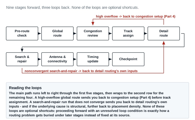
The same metrics, read at two points in the flow. The value of reading them twice is knowing which numbers are supposed to move and which must already be zero.
| Metric | Source | Healthy threshold | After global route | After detail route | Status |
|---|---|---|---|---|---|
| Connectivity — must reach zero by the end of detail routing | |||||
| Routed percentage | report_route_status | 100% at detail-route exit | 100% planned | 100% | PASS |
| Unrouted nets | report_route_status | 0 at detail-route exit | n/a (no geometry yet) | 0 | PASS |
| Opens | check_routes -open_net true | 0 — always, no exceptions | n/a | 0 | PASS |
| Shorts | check_routes | 0 — always, no exceptions | n/a | 0 | PASS |
| Physical rules — expected to be non-zero mid-flow, zero at exit | |||||
| Routing DRC violations | check_routes -drc true | 0, or every remaining item dispositioned | n/a | 248 → 0 after search-and-repair | PASS |
| Antenna violations | check_routes -antenna true | 0, or every remaining item dispositioned | n/a | 37 → 0 after antenna handling | PASS |
| Resource — expected to move, judged against a stated budget | |||||
| Congestion overflow H | report_congestion | <1%, no persistent hot spot | 0.15% | 0% | PASS |
| Congestion overflow V | report_congestion | <1%, no persistent hot spot | 0.05% | 0% | PASS |
| Total wire length | report_route (illustrative) | Within the pre-route estimate +10% | ~810,000 µm estimate | 842,300 µm | PASS |
| Via count | report_route (illustrative) | No unexplained jump versus estimate | not reported pre-detail | 138,240 | PASS |
Read it: The two value columns are the whole point. Opens and shorts are zero in both columns because they are never acceptable at any point. DRC and antenna counts are large after detail routing and zero only after search-and-repair and antenna handling — a non-zero count there is expected, and a non-zero count at stage exit is not. Routed percentage means something different in each column: after global routing it means every net has a plan, after detail routing it means every net has metal. Reading those two as the same number is one of the most common beginner mistakes in this stage.
Values are this chapter's illustrative teaching data for the Nimbus‑8 u_sens_tile partition.
When the standard flow is not the right tool
Everything in Part 5 assumes the standard, automatic routing flow is the right tool for every net. Most of the time it is. This Part covers the case where it is not. Here a net, or a small group of nets, needs routing built with a separate, specialized custom router. That geometry is then brought into the same design the standard flow just finished routing. This is not a footnote. A custom-routed net still has to pass every verification this chapter requires, and the design still has to return to one unified postroute optimization flow afterward. Treat this Part as a detour with a clearly marked on-ramp and a clearly marked off-ramp back to Part 7, not a separate chapter.
Imagine one bus on the chip that has to be built to a tolerance the automatic router cannot promise. Everything else on the die is still routed normally, around it. That is the whole shape of this Part: a short, well-marked detour off the standard flow, and a clearly marked way back onto it.
What routing with a custom router means
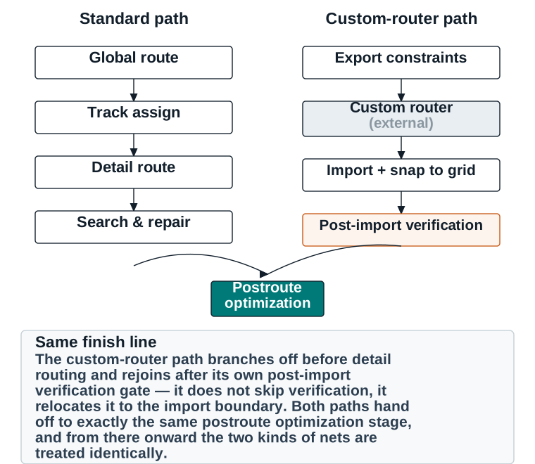
In the standard flow, ICC2's own router makes every decision: which GCells a net passes through, which tracks it uses, which layers, which vias. Routing with a custom router means that, for a specific net or net group, those decisions are made outside that automatic flow. They are made by a separate routing engine, by a specialized methodology, or in some cases by careful manual construction. The resulting geometry is then imported into the design as if it had been routed normally. The rest of the design, and the rest of this chapter's flow, is completely unaffected. Standard-router nets are still routed by Part 5's sequence. The custom-routed nets simply arrive by a different path, then rejoin the same postroute optimization and signoff flow from Part 7 onward.
Standard path versus custom-router path, side by side
Situations in which custom routing may be appropriate
- A small group of nets needs a routing property the standard router cannot guarantee directly. That might be exact matched length within a tight tolerance, full symmetric shielding on both sides for the entire net length, or a specific fixed topology required by an analog or mixed-signal interface.
- A hard macro or IP block ships with its own required routing methodology for its interface nets, as a condition of using that IP.
- A structure (a memory-compiler bus, a differential pair set) is repeated identically many times, and a specialized generator produces more consistent, verifiable geometry than per-instance automatic routing would.
- An SI-critical net group needs an iterative, engineer-in-the-loop routing process beyond what a fully automatic SI-driven strategy (Part 4) can practically achieve.
Required prerequisites before using a custom router
Every readiness item from Part 3 still applies to the design as a whole. Three things are needed in addition. First, the net group intended for custom routing must be explicitly identified and excluded from the standard route_detail pass. It can instead be routed standard-first as a placeholder, then deliberately ripped up. Second, the routing rules that group must obey — layer, width, spacing, via and blockage — must be documented and exportable in a form the custom router understands. Third, a rollback checkpoint must exist from immediately before the export, independent of the general pre-route checkpoint. A custom-router import that goes wrong needs its own clean return point.
Data and constraints passed to the custom router
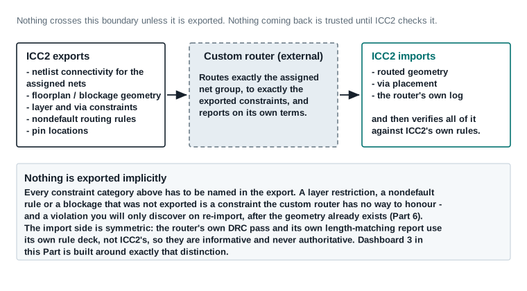
At minimum, the export must carry six things. It must carry exact pin locations and net connectivity for every net in the group, with nothing left to be inferred. It must carry the layer set the group is restricted to. It must carry the nondefault routing rule, width and spacing, that each net must obey. It must carry via constraints, including any redundant-via requirement. It must carry every blockage and keepout the group's region must respect. And for clock, critical or special nets in the group, it must carry the specific intent behind their assignment. That intent may be a matched-length tolerance, a shielding requirement or a topology constraint. Whatever it is, state it as an explicit, checkable number rather than leaving it implicit. A constraint left implicit is a constraint the custom router has no way to honor.
How clock nets, critical nets, and special nets are treated
A clock net routed by a custom router still has to meet the same skew and latency intent Clock Tree Synthesis established. The custom router's export must therefore carry the relevant balance-group or matched-length requirement explicitly. The post-import verification must then re-run report_clock_qor on the affected clocks. Do not assume the custom route preserved skew simply because it connects correctly. A critical net's NDR and shielding requirements are exported exactly as documented in Part 4 — the custom router does not get to substitute its own default width/spacing. A special net, such as a reset tree or a scan chain, carries whatever topology or fanout-order constraint made it special in the first place. If the custom router's methodology cannot express that constraint, that net is not a candidate for this path.
Running the custom-router path
Custom-router step 1 of 4 — Exportwrite_def
Package the assigned net group's connectivity, geometry constraints, and blockages for the custom router.
- ObjectiveProduce a complete, self-contained constraint package the custom router can act on without further clarification.
- WhyThe custom router has no access to ICC2's live design state; everything it needs must be handed over explicitly.
- Exact action
icc2_shell> write_def -objects [get_nets {ADC_BUS[*]}] -include {nets routing_rules vias blockages} sens_adc_export.def
- Option explanation
-includelists every constraint category being exported; leaving one out silently is the single most common cause of a custom-router import problem (Part 9).
Custom router run (outside ICC2)
The specialized router or methodology produces geometry for the exported net group only.
- ObjectiveGenerate matched-length, shielded, or otherwise specially-constrained geometry that satisfies the exported requirements.
- WhyThis is the entire reason the custom-router path was chosen — a property the standard flow could not directly guarantee.
- Expected resultA routed geometry file (DEF or equivalent) covering exactly the exported net group, plus the custom router's own completion report.
- Option explanationEvery custom router has its own settings; the one non-negotiable requirement is that its output stays within the exported layer, width, spacing, and blockage constraints — verified next, not assumed.
read_def
Bring the custom router's geometry into the ICC2 database as ordinary routed shapes.
- ObjectiveMerge the custom-routed geometry into the design so it is indistinguishable, from a database standpoint, from standard-routed geometry.
- WhyEvery downstream step — extraction, timing, DRC, signoff — must see one unified, consistent routed database.
- Exact action
icc2_shell> read_def -include {nets routing_rules vias blockages} sens_adc_export.def
- Option explanationThe option
-includelimits the read to the same constraint categories exported bywrite_def. ICC2's own DEF grid units are set by the technology file. So a coordinate-grid mismatch between the custom router and ICC2, which is Part 9's first troubleshooting example, is corrected before export rather than with an import-time snap option.
check_routes on the imported net group only
A fast, scoped check before running the full post-import verification set below.
- ObjectiveCatch a gross import failure immediately, before spending time on the full verification checklist.
- WhyAn obviously broken import is cheaper to catch and re-import now than after a full extraction and timing update.
- Exact action
icc2_shell> check_routes -nets [get_nets {ADC_BUS[*]}]
- Expected resultZero errors on this scoped check; any failure here means re-export or re-import before proceeding to full verification.
Checks required immediately after custom routing
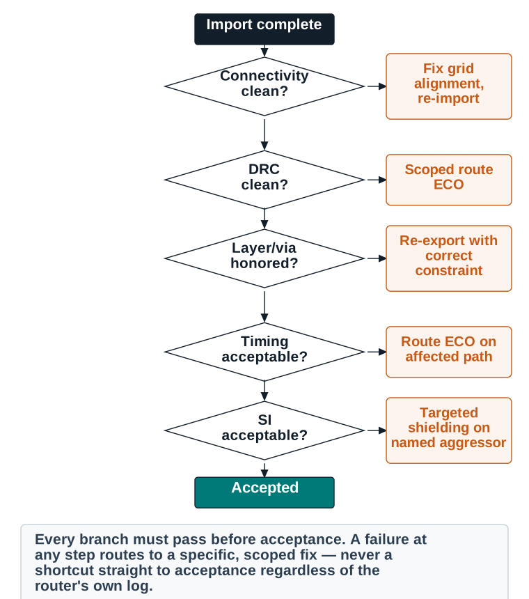
A successful import message from read_def is not evidence the custom-routed result is correct — it only means the geometry was accepted into the database without a format error. Every item below must be checked explicitly. Never treat import success alone as acceptance.
Command verification notecheck_connectivity, report_layer_usage, extract_rc, report_crosstalk_delay, and report_route below remain this chapter's illustrative pseudocode — no command by these names was found in the real Synopsys reference; see qa/command-verification.csv. Every other command in this table (check_routes, update_timing, report_noise, report_congestion) is independently verified against it.
| Check | Command | What it confirms |
|---|---|---|
| Connectivity verification | check_connectivity -nets [get_nets sens_adc_in[*]] | Every imported net is one electrically connected piece, matching source netlist connectivity. |
| Open and short detection | check_routes -open_net true | No broken or unintentionally merged nets from a grid or coordinate mismatch. |
| Geometry and design-rule verification | check_routes -drc true | Imported geometry obeys the same width/spacing rules as standard-routed geometry. |
| Layer and via verification | report_layer_usage -nets [get_nets sens_adc_in[*]] | The router actually stayed within the exported layer and via constraints. |
| Timing and parasitic update | extract_rc; update_timing -full | The custom route's real electrical effect on timing, not an assumption that matched-length routing implies matched delay. |
| Signal-integrity verification | report_noise; report_crosstalk_delay | The shielding or spacing intent actually reduced coupling as intended. |
| Antenna verification | report_route -type antenna_violators | Custom-routed geometry is not exempt from antenna risk. |
| Incremental repair / ECO scope | report_congestion on neighboring regions | The custom route did not silently starve routing resource from adjacent standard-routed nets. |
Restrictions, limitations, and recovery strategy
A custom-router path has real limitations worth stating plainly. It only covers the net group it was explicitly given. It has no awareness of the rest of the design's congestion or timing state. That is exactly why the post-import checks re-verify against the whole design, not just the imported nets in isolation. It cannot participate in ICC2's own incremental search-and-repair. If the import introduces a DRC violation, that violation is fixed with a standard, scoped route ECO (Part 2, Part 7) on the affected shapes, not by rerunning the custom router. The custom router's own internal metrics, such as its length-matching report and its own DRC pass, use a different rule model than ICC2's. They are informative but not authoritative. ICC2's own checks, run after import, are what decide acceptance.
Suppose verification fails in a way a scoped route ECO cannot cleanly fix. The safe recovery is then to restore the rollback checkpoint saved before export, correct the constraint export or the custom router's configuration, and repeat the four-step process above. Do not attempt to patch a structurally wrong import by hand-editing geometry directly; the constraint mismatch that caused the failure will still be present the next time this net group needs to change.
How the design returns to normal postroute optimization
Once every post-import check above passes — connectivity, DRC, layer/via, timing update, signal integrity, antenna — the custom-routed net group is, from this point forward, ordinary routed geometry. It is included in the same save_block checkpoint as every standard-routed net. The same postroute optimization pass in Part 7 can touch it, resizing a buffer near its endpoints if timing requires it. The same stage-exit checklist in Part 12 applies to it, with no special exception. The only trace that a custom router was used is the documentation of why, plus the evidence that its verification passed. Both belong in the stage-exit checklist's evidence column, not in a separate, second checklist.
Evidence required before accepting a custom-routed result
| Item | Classification |
|---|---|
| Constraint export complete (connectivity, layers, NDR, vias, blockages) | PASS / REVIEW / BLOCKER |
| Import completed, aligned to ICC2's manufacturing grid | PASS / REVIEW / BLOCKER |
| Connectivity matches source netlist, zero opens/shorts | PASS / REVIEW / BLOCKER |
| Routing DRC clean on imported geometry | PASS / REVIEW / BLOCKER |
| Layer and via constraints honored | PASS / REVIEW / BLOCKER |
| Timing re-verified on extracted, routed parasitics (not assumed from custom router's own report) | PASS / REVIEW / BLOCKER |
| Signal integrity re-verified (crosstalk delay, noise) | PASS / REVIEW / BLOCKER |
| Antenna re-verified on imported geometry | PASS / REVIEW / BLOCKER |
| Neighboring regions re-checked for congestion side effects | PASS / REVIEW / BLOCKER |
Part 10's worked example fills in this exact table with real Nimbus‑8 evidence; this Part defines what has to be checked and why.
Worked example: why the Nimbus‑8 ADC-input bus needs a custom router
Nimbus‑8's 16-bit ADC-input bus, sens_adc_in[15:0], feeds an on-die analog front end. That front end demands three things of the bus. Every bit's wire length must be matched to within ±5 µm of the others. The whole run needs full symmetric grounded shielding. And the bus needs a fixed two-layer (M6/M7) topology, to keep it away from the noisier digital layers below. The standard SI-driven and timing-driven routing strategies in Part 4 can approximate matched length, and they can apply NDR-based shielding. Neither can guarantee the exact, uniform tolerance and full-length symmetric shielding this interface's specification requires across all sixteen bits at once. That is exactly the situation Part 6 describes as appropriate for a custom-router path. The full run, with real before/after numbers, is in Part 10.
Troubleshooting example: a connectivity problem in imported routing
Symptom: check_connectivity reports 2 opens after import
- Likely cause
- The custom router's internal coordinate grid did not exactly match ICC2's manufacturing grid; two via locations landed a fraction of a grid unit off, breaking the connection to the layer above.
- Checks
check_routes -open_net true -report_all_open_nets trueto get the exact coordinates and nets involved.- Evidence
- Both open locations correspond to via positions, not wire midpoints — a strong signal of a grid-alignment problem rather than a routing-logic error.
- Corrective action
- Correct the coordinate/grid mapping in the custom router's output (or the
-convert_sites/units settings used on re-export), then re-runread_def; ICC2's DEF reader has no import-time snap option, so the fix has to happen before the file is re-read. - Required rechecks
- Full post-import verification table above, repeated from the top — do not assume fixing the two opens is sufficient without rechecking DRC and timing too.
- Safe rollback point
- The checkpoint saved before the original export.
Troubleshooting example: physically valid but electrically unacceptable
Symptom: import passes connectivity and DRC, but a nearby critical path fails setup
- Likely cause
- The custom router's wide shielded geometry consumed more routing resource than the standard flow would have in that region, forcing an unrelated timing-critical net into a detour during the earlier global-routing pass.
- Checks
report_congestionin the region immediately surrounding the imported bus, andreport_timingon the newly failing path, tracing its route geometry.- Evidence
- The failing path's routed length is measurably longer than its global-routing estimate, and its detour visibly routes around the shielded bus's footprint.
- Corrective action
- A targeted route ECO on the detoured critical net, once local resource is freed slightly. Confirming that the shield spacing is not wider than the specification actually requires is one way to free it. This is not a rework of the custom-routed bus itself, which is meeting its own real requirement.
- Required rechecks
- Re-verify timing on the repaired path and re-confirm the custom-routed bus is still DRC- and connectivity-clean after the neighboring ECO.
- Safe rollback point
- The checkpoint saved immediately after the original import, before the neighboring route ECO.
The structure of this board is the lesson of this Part. The second column is the custom router's own account of its work. The third column is the ICC2 check that actually decides whether the geometry is acceptable. Only the third column is authoritative.
| Check | What the custom router reports | The ICC2 check that decides it | Threshold | Result | Status |
|---|---|---|---|---|---|
| Connectivity | “16/16 nets routed, 0 unconnected” | check_connectivity -nets [get_nets sens_adc_in[*]] against the ICC2 netlist | Every net one connected piece, matching the source netlist | Clean — matches source netlist | PASS |
| Opens and shorts | “no violations” | check_routes -nets [get_nets {ADC_BUS[*]}] | 0 opens, 0 shorts | 0 / 0 | PASS |
| Routing-grid alignment | “on-grid” per its own grid definition | ICC2 detail-route DRC on the imported geometry | Snapped to the ICC2 track grid, not the router's own grid | 0 off-grid shapes | PASS |
| Layer and via compliance | “M6/M7 only, per constraints” | report_layer_usage -nets [get_nets sens_adc_in[*]] (illustrative) | 100% of routed length on the exported layer set | 100% on M6/M7 | PASS |
| Design-rule cleanliness | “DRC clean” per the router's own rule deck | check_routes -drc true under the ICC2 technology file | 0 violations under the ICC2 rule deck | 0 DRC violations | PASS |
| Length matching | “matched to ±5 µm” | report_route bit-to-bit histogram (illustrative) | Worst-case bit-to-bit skew within ±5 µm | 3.2 µm worst case | PASS |
| Antenna | not reported by the custom router | check_routes -antenna true | 0 violators, or dispositioned | 0 violators | PASS |
| Timing impact on the bus itself | not reported by the custom router | extract_rc then update_timing -full, then report_timing | No new violating path on the imported nets | No new violator | PASS |
| Timing impact on neighbors | not reported by the custom router | report_timing on paths through the surrounding region | No new violating path anywhere | SIG_CRIT_017 and SIG_CRIT_038 dip to −0.008 ns | REVIEW |
| Signal integrity | “shielded per specification” | report_noise -all_violators after extraction | 0 noise violators on and around the bus | 0 violators | PASS |
| Neighboring-region congestion | not reported by the custom router | report_congestion scoped to the surrounding region | No new hot spot created by the shield footprint | Elevated locally by shield spacing | REVIEW |
Acceptance verdict for sens_adc_in[15:0]: 9 PASS, 2 REVIEW, both resolved by a scoped route ECO and re-verified → ACCEPTED into nimbus8_sens_tile_routed_postopt_v1.
Read it: Notice the four rows where the second column reads “not reported by the custom router.” Antenna, timing on the bus, timing on the neighbors and neighboring-region congestion are all effects the external router has no way to see. They depend on the rest of the ICC2 database, which it never received. Two of those four are the rows that came back REVIEW — a tool that reported nothing but success produced two real problems, both found only because this board asked ICC2 rather than the router. Both were then resolved by the route ECO described above, and the bus re-verified.
Values are this chapter's illustrative teaching data. The names report_layer_usage and report_route remain this chapter's illustrative pseudocode — see qa/command-verification.csv.
Closing timing, signal integrity, and power on real parasitics
Once wires are real, their resistance and capacitance are real too — and real numbers are rarely identical to the estimates every earlier stage used. Postroute optimization is the measured, evidence-driven process of finding exactly what changed for the worse and fixing it with the smallest change that works. It is not a loop of rerunning the same command hoping for a better result; every technique in this Part exists to answer a specific symptom a report has already shown you.
Picture the design at the moment you enter this Part. Every wire is real, and for the first time the timing numbers describe copper instead of a guess. Some of those numbers will have moved the wrong way. In practice this Part is about finding exactly which ones moved, and then changing as little as possible to move them back.
Command verification notereport_timing, report_constraint, and report_power cited below are independently verified against the real Synopsys ICC2 Tcl Command Reference; extract_rc remains this chapter's illustrative pseudocode — no standalone extraction command by that name was found in that reference. See qa/command-verification.csv.
Why timing changes after detailed routing
Every timing number computed before this stage — in Placement and Optimization, in Clock Tree Synthesis, even in Part 5's own initial global-routing estimate — is built from a model of what the wiring will probably look like. Real detail-routed wires almost never match that model exactly. Some nets route shorter than estimated. Some detour around congestion (Part 2) and route longer. Some get an NDR's extra width and lower resistance. And some end up with more parallel-run neighbors than the estimate assumed, so they pick up more coupling capacitance. Extraction accuracy — how precisely extract_rc measures the real geometry's resistance and capacitance — is what makes the resulting timing numbers trustworthy where the earlier estimates were only approximate. Postroute optimization exists because this is the first point in the flow where timing, transition, capacitance, crosstalk, and power are all being measured against reality instead of a prediction.
Setup repair
Setup violation repair
Restore positive setup slack on paths that regressed once routed parasitics replaced estimates.
- Problem and symptomsNegative setup slack (WNS/TNS) on one or more paths, worse than the pre-route baseline.
- Physical causeRouted resistance/capacitance on the path's nets is higher than the pre-route estimate assumed, most often from a detour (Part 2) or an unplanned parallel-run neighbor.
- TechniqueBuffer insertion or upsizing along the path, cell resizing at the endpoints, or a targeted route ECO if the detour itself is the root cause.
- PreconditionsRouting DRC, connectivity, and antenna already clean (Part 5); do not optimize timing on top of an unresolved physical problem.
- Expected physical changeNew or larger buffers/cells along the path; possibly a shorter route if the fix addressed a detour.
- Expected improvementWNS/TNS on the affected path returns to positive, ideally with margin, not just above zero.
- Possible negative side effectNew cell area and capacitance can push a neighboring, previously healthy path toward transition or hold trouble — recheck neighbors, not just the repaired path.
- Measurement method
report_timing -delay_type maxon the specific path, before and after.
Safe recovery: revert to the pre-repair checkpoint if the fix does not improve the target path within one or two iterations. Stop condition: positive slack with the project's required margin, on every path in every active scenario — not merely a slightly-less-negative number.
Hold repair
Hold violation repair
Add delay to a path arriving too early relative to its capturing clock edge.
- Problem and symptomsNegative hold slack, most often on a short, low-logic-depth path near a clock source.
- Physical causeThe data path is faster (lower delay) than the clock-skew margin between launch and capture flip-flops assumed.
- TechniqueInsert delay buffers (deliberately, not sized for drive strength) along the offending path.
- PreconditionsSetup repair on this same path should generally be finished first — fixing hold on a path that is about to be resized for setup wastes the hold fix.
- Expected physical changeOne or more small delay buffers added in series on the path.
- Expected improvementPositive hold slack with margin, on the specific corner(s) where the violation appeared.
- Possible negative side effectAdded delay can, in rare cases, push the same path's setup slack down at a different corner — always recheck setup at every corner after a hold fix.
- Measurement method
report_timing -delay_type minat every corner where hold is checked, not just the corner that originally failed.
Safe recovery: remove the inserted delay buffers and retry with a smaller increment if the fix overcorrects into a new setup violation. Stop condition: positive hold slack with margin at every required corner, with no new setup violation introduced.
Transition and capacitance repair
Max transition / max capacitance repair
Fix a signal edge that is too slow, or a driver loaded beyond its rated capacitance.
- Problem and symptomsA max transition or max capacitance violator reported on a specific pin, usually a driver with a long or heavily loaded net.
- Physical causeRouted wire capacitance (long run, wide NDR net, or high fanout) exceeds what the driving cell can switch within the technology's transition-time limit.
- TechniqueUpsize the driving cell, insert a buffer partway along the net to split the capacitive load, or reduce unnecessary NDR width if it was not actually required there.
- PreconditionsConfirm the net's NDR/shielding assignment (Part 4) was actually needed before assuming the violation requires a bigger driver.
- Expected physical changeA larger driver cell, or an added buffer partway along the net's route.
- Expected improvementTransition time and capacitance both within their design-rule limits.
- Possible negative side effectA larger driver adds area and power; an added buffer changes the net's topology and needs its own DRC/antenna recheck.
- Measurement method
report_constraint -all_violators -max_transitionand the equivalent-max_capacitanceflag, before and after.
Safe recovery: if upsizing does not resolve it, insert a buffer instead of continuing to upsize past the point of diminishing return. Stop condition: zero max transition and max capacitance violators, confirmed by report, not by the absence of a tool warning alone.
Fanout-related repair and crosstalk-aware optimization
Fanout repair and crosstalk/noise-driven optimization — Part A of 2: diagnosisFanout repair and crosstalk/noise-driven optimization
Restructure a high-fanout net's buffering, or specifically target crosstalk delay and noise violations.
- Problem and symptomsA net driving more receivers than one buffer can efficiently switch, or a victim net with crosstalk delay/noise violations concentrated near specific aggressor neighbors.
- Physical causeFanout: excess total load split across too few buffering levels. Crosstalk: coupling capacitance from a real, switching neighbor exceeding what the net's timing or noise margin can absorb.
- TechniqueFanout: rebalance the buffer tree, adding a level or redistributing receivers. Crosstalk/noise: apply shielding or a route ECO to increase spacing to the specific aggressor identified by the report (Part 8), or apply an NDR retroactively.
- PreconditionsIdentify the specific aggressor net from the crosstalk/noise report before attempting a fix — a generic “add spacing everywhere” approach wastes routing resource without addressing the actual pair involved.
Fanout repair and crosstalk/noise-driven optimization — continued
Expected result, side effects, measurement, and how to recover if the fix does not hold.
- Expected physical changeFanout: added buffer level. Crosstalk: added shield wire or increased spacing to the named aggressor.
- Expected improvementFanout: reduced load per buffer, improved transition. Crosstalk: reduced delta delay and noise glitch height on the victim, confirmed against its report thresholds.
- Possible negative side effectFanout: added buffer levels add latency. Crosstalk: adding a shield or spacing can require a local reroute of a third, unrelated net.
- Measurement method
report_timingfor fanout-driven delay; the crosstalk delay and noise reports named in Part 8 for SI fixes.
Safe recovery: revert the specific local change and retry with a narrower-scoped fix if a third net's reroute cascades into a new violation. Stop condition: fanout-related transition/capacitance violators at zero; crosstalk delay and noise violators at zero or explicitly dispositioned as sub-threshold and acceptable.
Cell sizing, cell movement, and route/via changes
Most of the repair techniques above resolve down to a small set of physical actions, applied in combination. Buffer insertion and resizing adds drive strength or splits load. Cell sizing chooses a stronger or weaker library cell for the same logic function. Cell movement nudges a cell slightly, where legalization rules permit, to shorten a specific critical connection. Route changes are made through a targeted route ECO. Via changes add redundancy, or promote a transition to a lower-resistance via definition. And layer promotion moves a net's run from a lower, more resistive layer to a faster upper layer, where resource allows. Detour reduction is often the highest-leverage of these. A path that fails setup because it was forced into a long detour (Part 2) is frequently better served by relieving the congestion that caused the detour, rather than by repeatedly upsizing drivers along it.
Clock-data interaction
A postroute fix that changes a data path's delay can change its relationship to the clock edges launching and capturing it. This is clock-data interaction. It is why every setup or hold fix above is followed by a recheck across all corners, not just the corner that originally failed. In rare cases, a data-path fix is better replaced by a small, deliberate clock-side adjustment rather than repeated data-path buffering. That means useful skew, applied cautiously and only when the project's methodology explicitly allows it. That decision belongs with a senior engineer, not a default first move.
Leakage, dynamic power, and area recovery
Power and area recovery
Once timing, transition, and SI are closed with real margin, recover power and area the earlier repairs spent generously.
- Problem and symptomsTotal power (leakage and/or dynamic) or area increased more than necessary during setup/transition/crosstalk repair, because early fixes are often made with margin to spare, not minimally.
- Physical causeOversized buffers/cells inserted during earlier repair steps, now carrying more slack than their path actually needs.
- TechniqueDownsize cells on paths with generous positive slack, remove redundant buffering where slack allows, consolidate near-duplicate fixes.
- PreconditionsOnly attempted after setup, hold, transition, capacitance, and SI are already closed — recovery must never reopen a violation that was just fixed.
Power and area recovery — continued
What the recovery pass should change, what it should improve, and how to prove it did neither harm nor nothing.
- Expected physical changeSelected cells downsized or removed; wire and via count essentially unchanged.
- Expected improvementLower leakage and/or dynamic power, lower area, measured against the post-repair (not pre-route) baseline.
- Possible negative side effectOver-aggressive downsizing can reopen a violation that was just closed — this is the most common single mistake in this technique.
- Measurement method
report_powerand a full timing re-check after every recovery pass, not only at the end.
Safe recovery: revert the specific downsizing change that reopened a violation; do not downsize further paths until the reopened one is confirmed clean again. Stop condition: measurable power/area improvement with zero new violations of any kind.
Design-rule and legality preservation, incremental optimization, and ECO routing
Every technique above must preserve two things that are easy to silently break while chasing a timing number. The first is design-rule preservation: a resized cell or a rerouted net must still be DRC-legal. The second is legality preservation: a moved cell must still sit on a legal site, and any nudge must respect the same placement legality rules Part 3 checked before routing. Postroute optimization runs in many small, targeted steps rather than one pass, so it is run incrementally, with each fix scoped to the specific path or net it addresses. ECO routing handles the physical rerouting a fix requires. Re-extraction then updates parasitics for exactly what changed, and reanalysis re-runs timing, DRC and SI checks on the updated state. Only then does the next fix begin.
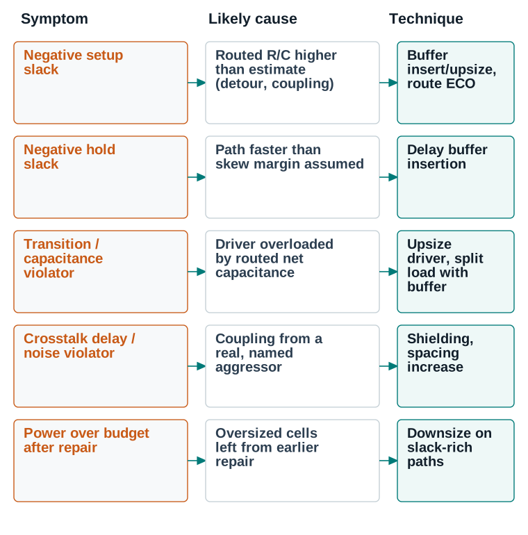
Convergence criteria and when not to keep optimizing
This board is the closure evidence for this Part. The before column is what extraction actually showed once the wires were real; the final column is what postroute optimization achieved; the difference between them is what this Part is for.
| Item | Source | Threshold | After routing, before postroute opt. | Final | Status |
|---|---|---|---|---|---|
| Timing, per scenario | |||||
WNS setup — func_ss_0p72v_125c | report_timing -delay_type max | ≥0 ns | −0.062 ns | +0.011 ns | PASS |
TNS setup — func_ss_0p72v_125c | report_timing -delay_type max | 0 ns | −0.31 ns (14 paths) | 0 ns | PASS |
WNS hold — func_ff_0p88v_m40c | report_timing -delay_type min | ≥0 ns | +0.021 ns | +0.019 ns | PASS |
TNS hold — func_ff_0p88v_m40c | report_timing -delay_type min | 0 ns | 0 ns | 0 ns | PASS |
WNS setup — test_ss_0p72v_125c | report_timing -delay_type max | ≥0 ns | +0.004 ns | +0.015 ns | PASS |
| Design rules on the routed netlist | |||||
| Max transition violators | report_constraint -all_violators | 0 | 11 | 0 | PASS |
| Max capacitance violators | report_constraint -all_violators | 0 | 4 | 0 | PASS |
| Signal integrity | |||||
| Crosstalk delay violators | report_crosstalk_delay (illustrative) | 0 | 16 | 0 | PASS |
| Noise violators | report_noise -all_violators | 0 | 3 | 0 | PASS |
| Power and clock | |||||
| Dynamic power | report_power | No unexplained rise versus the CTS baseline | 1.94 mW (peak during repair) | 1.87 mW | PASS |
| Leakage power | report_power | No unexplained rise versus the CTS baseline | 0.101 mW | 0.097 mW | PASS |
| Clock power share | report_power | Stable across postroute optimization | 0.42 mW | 0.41 mW | PASS |
| Clock global / local skew | report_clock_qor | ≤100 ps / ≤30 ps | 55 / 19 ps | 55 / 19 ps | PASS |
| Physical totals | |||||
| Total wire length | report_route (illustrative) | Recorded, not thresholded | 842,300 µm | 842,300 µm | PASS |
| Via count | report_route (illustrative) | Recorded, not thresholded | 138,240 | 138,240 | PASS |
Read it: Read the two value columns as a pair, row by row. Every timing row is named by scenario, not by “setup” and “hold” alone. A fix that closes setup in func_ss_0p72v_125c can open a hold violation in func_ff_0p88v_m40c. That is exactly why hold is re-checked at every corner after every setup repair, and why hold appears here at +0.019 ns rather than its pre-repair +0.021 ns. The power rows are last on purpose: power recovery runs only once every violation above it is already clear.
Values are this chapter's illustrative teaching data, not a real tool transcript.
Reading the reports that prove routing is healthy
Every technique in Parts 5 through 7 depends on being able to read the right report, find the right field, and know what a healthy value looks like. This Part is a reference for that skill — organized by what you are trying to learn, not by command name.
Think of the reports in this Part as instruments on a dashboard rather than as commands to memorize. Each one answers a single question about the routed design. Reading them in the wrong order sends you chasing a symptom instead of a cause, which is why the order here is deliberate.
Command verification noteMost command names below have now been checked against the real Synopsys ICC2 Tcl Command Reference and are independently VERIFIED (exact syntax corrected where this chapter's earlier form differed) — including report_timing, report_congestion, report_noise, report_clock_qor, report_power, check_routes, and update_timing. The names report_route_status, report_route, report_layer_usage, report_crosstalk_delay, check_connectivity, check_pin_access, and extract_rc remain this chapter's illustrative pseudocode — no command by these names was found in that reference. See qa/command-verification.csv for the per-command sourcing, page citations, and status.
Route completion, connectivity, and physical-rule quality
report_route_status
The first report to run after any routing pass — is the design actually, physically complete?
- Why this report is usedIt is the single fastest way to confirm route completion, connectivity, and DRC/antenna status in one place.
- When to run itAfter every routing stage in Part 5, and again after every custom-router import (Part 6).
- Command form
report_route_status -verbose - Fields to read firstPercent routed, unrouted net count, open/short count, DRC violator count, antenna violator count.
- Healthy evidence100% routed, zero unrouted nets, zero opens, zero shorts, zero (or fully dispositioned) DRC and antenna violators.
- Unhealthy evidenceAny nonzero unrouted, open, or short count — these are never acceptable, unlike some DRC/antenna items which can be dispositioned.
- Common misinterpretationTreating 100% routed as equivalent to “done” — it only confirms connectivity exists, not that it is legal, fast, quiet, or low-power (Part 1).
- Next engineering actionIf unrouted/open/short is nonzero, return to Part 5 or Part 9 before doing anything else; a design with connectivity problems is not ready for any other analysis.
| Metric | Command | Healthy evidence |
|---|---|---|
| Via quality / redundant-via coverage | report_route -type via_summary | Redundant vias present on every net flagged in Part 4; no via reported as a single point of failure on a critical net. |
| Layer usage | report_layer_usage | Wire length distribution matches the intended layer plan — clock/critical nets on their assigned layers, no unplanned heavy usage of a restricted layer. |
| Wire-length distribution | report_route -type wire_length_histogram | Distribution roughly matches the pre-route estimate; a long tail of unusually long nets suggests unresolved detours. |
| Congestion / remaining overflow | report_congestion -mode summary | Overflow at or near zero everywhere; no repeat hot spot from Part 3/Part 5. |
| Detours | report_route -type detour | Detoured nets confined to known congested regions, with a documented reason, not scattered unexplained across the design. |
| Pin accessibility | check_pin_access | Zero unreachable pins remaining after routing (should already have been zero at Part 3 readiness). |
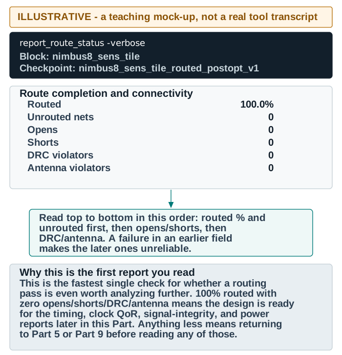
Timing, transition, and capacitance
report_timing and report_constraint
Confirm setup, hold, transition, and capacitance are healthy on routed, extracted parasitics.
- Why this report is usedIt is the ground truth for whether the design meets its timing intent now that wires are real.
- When to run itImmediately after Part 5's extraction/timing-update stage, and after every postroute optimization fix (Part 7).
- Command form
report_timing -delay_type max -scenarios [all_scenarios];report_constraint -all_violators - Fields to read firstWNS, TNS, violating-path count, per scenario; for report_constraint, violator count by type (max_transition, max_capacitance).
- Healthy evidencePositive WNS with required margin in every active scenario; zero max transition/capacitance violators.
- Unhealthy evidenceNegative WNS, or a positive WNS with much larger TNS than expected, signaling many small violations rather than one outlier.
- Common misinterpretationChecking only the worst-case (max) corner and assuming hold (min) is automatically fine — the two must both be checked, at every corner.
- Next engineering actionFeed the specific violating paths into Part 7's setup/hold/transition repair techniques; do not re-run the whole routing flow hoping for a different result.
Clock quality of result after routing
Clock latency and skew, already verified once in Clock Tree Synthesis, must be re-checked after routing — the same report_clock_qor command from that chapter, now run against routed, extracted parasitics rather than CTS-time estimates. A clock that was healthy on estimated parasitics can still shift once its real routed geometry (especially if any clock-net detail routing was deferred into this stage) is measured. Read it the same way: DRC violators at zero first, then latency and global/local skew against the project's targets. A meaningful skew regression from the CTS-time numbers is a signal worth tracing back to a specific branch before accepting the design.
Signal integrity: crosstalk delay, noise, and coupling
report_crosstalk_delay and report_noise
Confirm coupling between neighboring nets has not corrupted timing or logic-level integrity.
- Why this report is usedStatic timing and DRC reports alone cannot see crosstalk — it requires its own dedicated analysis of aggressor/victim switching relationships.
- When to run itAfter routed timing is otherwise healthy, and again after any SI-related postroute fix (Part 7).
- Command form
report_crosstalk_delay -nets [all_nets] -threshold 0.05(illustrative — seeqa/command-verification.csv);report_noise -all_violators - Fields to read firstVictim net name, worst aggressor, delta delay (crosstalk delay) or glitch height (noise), and whether it crosses the violation threshold.
- Healthy evidenceZero nets over the delta-delay or glitch-height threshold, or a small, explicitly reviewed and accepted residue on non-critical nets.
- Unhealthy evidenceViolations concentrated on already timing-critical or logic-sensitive nets (resets, enables), which compound with other risks.
- Common misinterpretationAssuming a clean static timing report means crosstalk is fine — crosstalk delay is a separate, additive effect on top of ordinary timing and must be checked separately.
- Next engineering actionTrace the named aggressor/victim pair and apply Part 7's crosstalk-aware optimization directly to that pair, not a broad, unscoped spacing increase.
Power after routing
Run report_power -scenarios [all_scenarios] after routing and again after postroute optimization. Read dynamic power, leakage power and clock power as three separate lines, not one combined number. Dynamic power is most sensitive to routed capacitance, so NDR width, shielding and detours all move it. Leakage tracks total cell area and library cell choice. Clock power reflects the clock tree's own buffer count and activity. A meaningful increase in dynamic power after postroute optimization is expected if setup repair required real buffering. The question is not whether power increased during repair. It is whether the area and power recovery step in Part 7 brought it back down once timing was closed.
QoR and area changes, scenario consistency, and log review
Compare the design's overall quality-of-result summary against the Part 3 baseline and the Part 5 post-route baseline. The summary covers total cell count, total area, total wire length and via count. A large, unexplained jump in any of them after postroute optimization is worth understanding before you accept the design. Confirm that every active scenario shows consistent results, not just the primary one (Part 3, readiness item 4). A design that looks perfect in the typical corner but was never checked at a fast or slow corner is not actually verified. Finally, review the full run log for warnings and errors, not just the summary reports. A report can look clean while the log carries a warning that deserves attention, such as a degraded fallback where a search-and-repair iteration limit was reached.
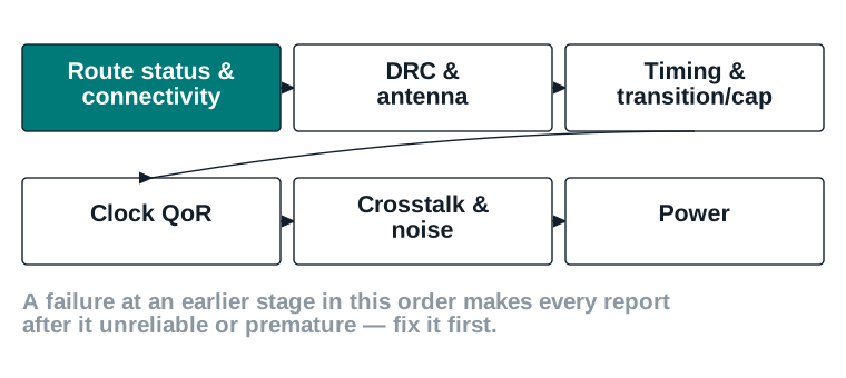
GUI-based analysis
Reports tell you a number; the layout viewer shows you where and why. For any violation that a report alone does not make obvious, open the layout and use the following habits.
- What to display. Show only the layer(s) and net(s) relevant to the violation being investigated — displaying every layer at once hides the specific problem in visual noise.
- What colors or markers mean. This guide's convention marks a healthy/accepted element in teal, a flagged or violating element in orange, and a fixed structural element (a blockage, a shield) in navy outline — consistent with every figure in this chapter.
- Locating a reported violation physically. Most report commands accept a
-highlightor equivalent option that selects the exact shape or net in the layout; use it instead of manually searching coordinates. - Correlating a report entry with the layout. Cross-check the report's coordinates or net name against what is highlighted — a mismatch usually means the report is describing a different (often nearby) instance than the one visually inspected.
- Distinguishing a local symptom from a global problem. Zoom out one level after inspecting the specific violation — a single detour is local; a whole region shaded with detours is a congestion problem requiring Part 4/Part 5 treatment, not a one-net fix.
- Confirming a visual repair is numerically valid. A fix can look correct in the layout, with spacing now visibly wider or the route now visibly shorter. It must still be re-confirmed with the actual report command. Visual inspection catches gross errors, but it cannot substitute for the precise numeric check.
What to do when something does not converge
Every card below follows the same shape: likely causes, what to check, what evidence confirms the cause, the corrective action, what to recheck afterward, and a safe rollback point. Work through them in this order when a symptom is unclear: physical and connectivity problems first, then design-rule problems, then timing, SI and power problems. An unresolved earlier-category problem can produce misleading symptoms in a later one.
Picture yourself at the point where a report has just told you something is wrong and you do not yet know why. In practice that is where most routing time is actually spent. So this Part is organized the way a real diagnosis runs: category first, cause second, fix last.
Command verification noteThe full statement of what was verified and what is illustrative is in Part 8. For this Part: check_routes, report_timing, report_congestion and report_noise are VERIFIED against the Synopsys reference, while report_route_status, check_connectivity and extract_rc are this chapter’s illustrative pseudocode.
Unrouted nets
- Likely causes
- Unreachable pin, severe local congestion, a blockage placed after routing began, or a routing-rule conflict the router could not resolve.
- Checks
report_route_status -verbosefor the exact net list;check_pin_accessandreport_congestionat each unrouted net's location.- Evidence
- Unrouted nets cluster in one region (congestion) versus scattered at specific pins (access) versus all touching one blockage (obstruction).
- Corrective action
- Congestion: Part 4 relief and rerun global routing. Access: adjust placement/orientation. Obstruction: confirm the blockage was intended; if so, route around it deliberately with a route guide.
- Required rechecks
- Full
report_route_statusafter the fix; confirm no new unrouted nets appeared nearby. - Safe rollback point
- The pre-detail-route checkpoint (Part 5, Stage 5).
- Condition that blocks progress
- Any unrouted net at all — never proceed to postroute optimization with unrouted nets outstanding.
Opens and shorts
- Likely causes
- A search-and-repair fix that disconnected a shape, a custom-router grid mismatch (Part 6), or an extraction/database inconsistency after a manual edit.
- Checks
check_connectivity -type all -verbose(illustrative) andcheck_routes -open_net true -report_all_open_nets truefor exact locations.- Evidence
- Open/short coordinates correspond to a via (grid/geometry problem) versus a wire body (search-and-repair side effect).
- Corrective action
- A scoped route ECO on exactly the affected net; for a custom-router-caused open, follow Part 6's re-import procedure instead of hand-patching.
- Required rechecks
- Re-run connectivity check on the full design, not just the repaired net — a short can involve a second net that also needs re-verification.
- Safe rollback point
- The last clean checkpoint before the change that introduced the problem.
- Condition that blocks progress
- Any open or short at all; there is no acceptable disposition for either.
Persistent DRC violations
- Likely causes
- Genuine local resource shortage (too many nets, too little space, given the assigned rules), or an NDR/shielding assignment that is not physically achievable in a tight region.
- Checks
report_route -type drc_violators -verbose(illustrative), cross-checked againstreport_congestion -mode summaryat the same coordinates.- Evidence
- Violations remain at the same coordinates across repeated search-and-repair iterations without decreasing.
- Corrective action
- Relax the local NDR/shielding requirement if it is not strictly required there, add routing resource (blockage relief, layer availability), or accept a documented, reviewed disposition if the violation is genuinely benign.
- Required rechecks
- Re-run search-and-repair after any resource or rule change; confirm the violation count actually drops.
- Safe rollback point
- The checkpoint before search-and-repair began (Part 5, Stage 6).
- Condition that blocks progress
- Any undispositioned DRC violation remaining at stage-exit (Part 12).
Congestion hot spots and excessive detours
- Likely causes
- Local placement density too high for available routing resource, an overly broad NDR/shielding assignment consuming shared tracks, or a blockage placed without enough surrounding relief.
- Checks
report_congestion -mode summaryandreport_route -type detour(illustrative) at the same region.- Evidence
- Overflow and detoured-net count both elevated in the same GCells across multiple routing passes.
- Corrective action
- Part 4 congestion-driven setup (route guides, blockage relief); if structural, return to placement density adjustment.
- Required rechecks
- Rerun global routing and congestion report after the fix; confirm the specific region improved, not just the design-wide average.
- Safe rollback point
- The pre-global-routing checkpoint.
- Condition that blocks progress
- Unresolved overflow in a region also driving DRC violations or timing failures.
Pin-access failures
- Likely causes
- A macro or cell oriented so its pin faces a blockage or another macro; insufficient placement halo around a dense pin cluster.
- Checks
check_pin_access -verbosefor the exact pin and its blocked direction(s).- Evidence
- The pin has zero legal track access on any adjacent layer, confirmed visually in the GUI (Part 8).
- Corrective action
- Adjust macro orientation or placement halo; for a standard cell, a small legal placement nudge.
- Required rechecks
- Rerun
check_pin_accessand confirm the net routes cleanly afterward. - Safe rollback point
- The pre-placement-adjustment checkpoint.
- Condition that blocks progress
- Any pin with zero access remaining before routing is attempted.
Via-related failures
- Likely causes
- Illegal via enclosure in a tight region, a missing redundant via on a net that requires one (Part 4), or a via stack that could not complete through all intermediate layers.
- Checks
report_route -type via_summaryand the specific DRC message for enclosure/spacing.- Evidence
- Via violations cluster at the same layer transition across multiple nets in a region — a resource problem, not an isolated error.
- Corrective action
- Adjust via rule or spacing locally, or relieve resource in that region; for missing redundancy, rerun with the redundant-via policy explicitly applied.
- Required rechecks
- Redundant-via coverage report and DRC recheck on the affected region.
- Safe rollback point
- The checkpoint before the via-affecting change.
- Condition that blocks progress
- Any illegal via remaining, or missing required redundancy on a critical net at stage-exit.
Antenna violations
- Likely causes
- A long single-layer run with no antenna-aware routing enabled (Part 4), or a diode-insertion site exhausted locally.
- Checks
report_route -type antenna_violators -verbose.- Evidence
- Violating nets correlate with long, low-layer runs, and/or a region with few available diode cell sites.
- Corrective action
- Enable antenna-aware routing (Part 4) and rerun; for a residual violation, apply a layer jumper where no diode site is reachable.
- Required rechecks
- Rerun the antenna report after every fix; confirm zero violators before proceeding.
- Safe rollback point
- The pre-antenna-fix checkpoint (Part 5, Stage 7).
- Condition that blocks progress
- Any undispositioned antenna violator at stage-exit.
Timing regression after routing: setup, hold, transition, and capacitance violations
- Likely causes
- Routed parasitics higher than pre-route estimate (setup/transition/capacitance), or a path faster than expected (hold), as described in Part 7.
- Checks
report_timingandreport_constraint -all_violators, compared against the Part 3 baseline.- Evidence
- Regression concentrated on detoured or heavily loaded nets, confirmed by cross-referencing Part 8's wire-length and congestion reports.
- Corrective action
- Apply the matching Part 7 repair technique (setup, hold, transition, or capacitance repair) to the specific violating path.
- Required rechecks
- Full timing re-check at every corner after each fix, not just the corner that originally failed.
- Safe rollback point
- The checkpoint saved at the end of Part 5 (Stage 9), before postroute optimization began.
- Condition that blocks progress
- Any required-scenario violation remaining at stage-exit.
Crosstalk delay and noise violations
- Likely causes
- Insufficient spacing or missing shielding on a net running parallel to a real, switching aggressor.
- Checks
report_crosstalk_delayandreport_noise, both named-aggressor forms (Part 8).- Evidence
- The named aggressor is a genuinely active, high-activity net, not a false positive from an always-quiet signal.
- Corrective action
- Apply Part 7's crosstalk-aware optimization: shielding or spacing increase against the specific named aggressor.
- Required rechecks
- Re-run both SI reports after the fix; confirm the specific pair cleared, not just the design-wide count.
- Safe rollback point
- The checkpoint before the SI-driven route ECO.
- Condition that blocks progress
- Any violation on a timing-critical or logic-sensitive net remaining undispositioned.
Unexpected power increase
- Likely causes
- Oversized buffers/cells left over from setup or transition repair, never recovered (Part 7's power/area recovery step skipped or incomplete).
- Checks
report_powercompared against the Part 5 post-route baseline, broken out by dynamic/leakage/clock power.- Evidence
- Power increase correlates in time with a specific repair pass, traceable in the checkpoint history.
- Corrective action
- Run Part 7's power/area recovery step explicitly, downsizing where slack allows.
- Required rechecks
- Full timing re-check after every downsizing change, to confirm no violation reopened.
- Safe rollback point
- The checkpoint immediately before the recovery pass, if a downsize reopens a violation.
- Condition that blocks progress
- Power outside the project's budget with no recovery attempted.
Clock QoR regression after routing
- Likely causes
- Clock-net detail routing (if deferred into this stage) took a different physical path than the CTS-time estimate, or a nearby signal-routing change added coupling capacitance to a clock net.
- Checks
report_clock_qor(Part 8), compared directly against the Clock Tree Synthesis chapter's exit-checkpoint numbers.- Evidence
- Skew or latency regression traced to a specific clock branch, not a uniform shift across the whole tree.
- Corrective action
- A targeted route ECO on the affected clock branch, or additional shielding if the cause is coupling from a nearby signal net.
- Required rechecks
- Full
report_clock_qorre-run after the fix, plus a recheck of any data path timed against that clock. - Safe rollback point
- The checkpoint before clock-net detail routing began.
- Condition that blocks progress
- Skew or latency regression that pushes a previously healthy data path into violation.
Custom-router import problems and constraint loss during handoff
- Likely causes
- An incomplete constraint export (Part 6) — a layer, NDR, or blockage category left out — or a coordinate-grid mismatch at import.
- Checks
- The full post-import verification table in Part 6, run in order.
- Evidence
- The specific failing check (connectivity, DRC, layer/via, timing, SI) identifies which constraint category was lost.
- Corrective action
- Re-export with the missing constraint category included, or re-import with corrected grid alignment; see Part 6's two worked troubleshooting examples.
- Required rechecks
- The entire post-import verification table again, from the top, after any re-export or re-import.
- Safe rollback point
- The checkpoint saved immediately before the original export (Part 6).
- Condition that blocks progress
- Any post-import check failing, regardless of how the router's own internal report reads.
Clean geometry but failing timing
- Likely causes
- Routing satisfied every physical rule while still choosing a longer, more resistive, or more heavily coupled path than the design's timing budget can absorb.
- Checks
report_route_statusconfirmed fully clean, thenreport_timingshowing the actual violation.- Evidence
- DRC/connectivity are all zero, yet WNS is negative or transition/capacitance violators are nonzero.
- Corrective action
- This is exactly what Part 7 exists for — apply the matching repair technique; it is not a routing bug to chase further in Part 5.
- Required rechecks
- Standard Part 7 rechecks for whichever technique was applied.
- Safe rollback point
- The Part 5 Stage 9 checkpoint.
- Condition that blocks progress
- Timing violation remaining after Part 7 repair has been genuinely attempted, not skipped in favor of rerouting alone.
Clean timing but failing physical rules
- Likely causes
- A postroute optimization fix (a buffer insertion, a route ECO) introduced a local DRC or antenna violation while correctly fixing the timing problem it targeted.
- Checks
report_route_statusre-run after every postroute fix, not only at the very end.- Evidence
- The new violation's location matches the exact site of the most recent postroute change.
- Corrective action
- A scoped route ECO or antenna fix at that specific site; do not accept a timing fix that traded in a physical-rule violation.
- Required rechecks
- Re-run route status and the original timing check together, confirming both are clean simultaneously.
- Safe rollback point
- The checkpoint immediately before the postroute fix that introduced the violation.
- Condition that blocks progress
- Any physical-rule violation introduced by a postroute change and not yet cleared.
Nonconvergent search-and-repair
- Likely causes
- A genuine resource shortage in one region that no number of search-and-repair iterations can solve, or two rule assignments (e.g., two overlapping NDR nets) that are jointly unsatisfiable in the available space.
- Checks
- Compare the violator count region-by-region across iterations; a flat or oscillating count in the same region is the signature.
- Evidence
- The same handful of nets appear in the violator list every iteration, never clearing.
- Corrective action
- Address the root resource or rule conflict directly (Part 4 relief, or relax one of the conflicting NDR assignments) rather than raising the iteration limit.
- Required rechecks
- Rerun search-and-repair from a fresh iteration count after the root cause is addressed.
- Safe rollback point
- The pre-detail-route checkpoint.
- Condition that blocks progress
- A violator count that has not measurably improved after a reasonable number of iterations (Part 5, Stage 6).
ECO route causing new violations, and warnings or errors remaining in logs
- Likely causes
- A route ECO scoped too narrowly, disturbing a neighbor net's spacing or blocking its only remaining track; or a run log warning (a degraded fallback, a skipped optimization step) left unread.
- Checks
- Re-run
report_route_statusand the relevant timing/SI report on the ECO's surrounding region; review the full run log, not only the summary. - Evidence
- A new violation appears immediately adjacent to the ECO's location and timestamp; a log warning names the specific step that degraded.
- Corrective action
- Widen the ECO's scope slightly to include the affected neighbor, or address the specific condition the log warning names.
- Required rechecks
- Full local re-verification after any ECO, plus a fresh log review after every major stage, not just at the very end.
- Safe rollback point
- The checkpoint immediately before the ECO.
- Condition that blocks progress
- Any unexplained warning or error remaining in the log at stage-exit (Part 12).
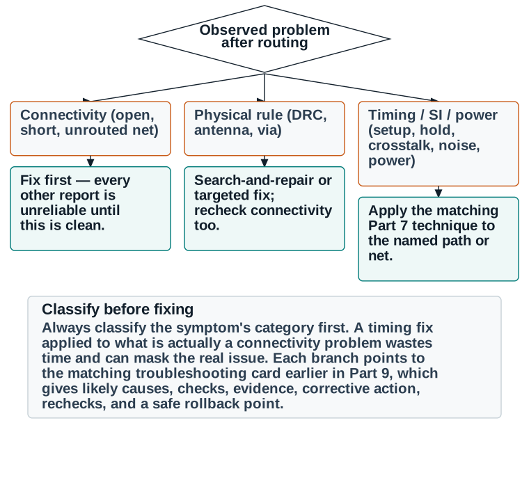
From a routed-clock checkpoint to a signed-off physical route
Nimbus‑8 enters this chapter exactly where the Clock Tree Synthesis chapter left it. Every clock is propagated and there are zero clock DRC violators. Global skew is 52 ps and worst local skew is 18 ps. The tree holds 700 clock buffers and inverters over 18,420 µm². This Part carries that checkpoint through readiness, routing strategy, the standard flow, the custom-router path for one sensitive bus, postroute optimization, and a final, evidence-backed PASS decision.
Notice as you read that nothing in this Part is new. It is the whole chapter run once, end to end, on one real block, with every number written down as it appears. Picture it as watching over a colleague's shoulder for a full day of work.
Scope. Nimbus‑8 as a whole is 9.90M standard cells, 72 SRAM macros and 1 DDR PHY hard macro in a 3.20 mm × 3.20 mm core (see Part 3). This worked example routes one named partition of it. That partition is u_sens_tile, the sensor-interface tile carrying the ADC input bus. It holds 46,200 standard cells and 2 SRAM macros in a 0.70 mm × 0.62 mm block at 79.6% utilization, with 48,612 signal nets. Every net count, wire length, via count and slack number below is that partition's, not the full chip's. Routing a full 9.90M-cell design is a hierarchical exercise that belongs to a later chapter; routing one partition end to end is what teaches the stage.
Command verification noteThis worked example's reported field values (latencies, slacks, violator counts) are fictional teaching data, not a real tool transcript. Most command names used below are independently verified against the real Synopsys ICC2 Tcl Command Reference. Those are check_legality, check_pg_connectivity, route_global, route_track, route_detail, check_routes, write_def, read_def, report_congestion, report_timing, update_timing, report_clock_qor, report_power, route_opt and save_block. Five others remain this chapter's illustrative pseudocode: check_pin_access, check_connectivity, extract_rc, report_crosstalk_delay and report_route. See qa/command-verification.csv for the full, per-command status.
Step 1: readiness review
| Item | Evidence | Classification |
|---|---|---|
| 1. Placement legality | check_legality: 0 violations | PASS |
| 2. CTS complete, clocks propagated | 612/560/588 ps latency, 52/18 ps skew, 0 DRC | PASS |
| 3. Power/ground routing complete | check_pg_connectivity: clean | PASS |
| 4. Required scenarios active | func_ss_0p72v_125c, func_ff_0p88v_m40c, test_ss_0p72v_125c all active | PASS |
| 5. Timing state entering routing | WNS(setup) +0.031 ns, WNS(hold) +0.045 ns | PASS |
| 6. Congestion state | Overflow 0.6% H / 0.3% V; one hot spot adjacent to the planned ADC-bus region | REVIEW — see Step 2 |
| 7. Design-rule constraints / layer availability | M2–M9 available; M6/M7 reserved for the ADC bus | PASS |
| 8. Blockages, keepouts, obstructions | Matches floorplan; ADC-bus keep-clear confirmed | PASS |
| 9. Pin accessibility, macro interfaces | check_pin_access: 0 unreachable | PASS |
| 10. High-fanout net plan | Scan enable and reset trees pre-buffered from Placement and Optimization | PASS |
| 11. Routing-rule / special-net assignment | 42 timing-critical nets assigned NDR_WIDE_2X; sens_adc_in[15:0] flagged for custom router | PASS |
| 12. Multivoltage considerations | Single-voltage design — not applicable | PASS |
| 13. Saved checkpoint | nimbus8_sens_tile_pre_route_v1, reopen verified | PASS |
| 14. Required reports / baseline evidence | Timing, congestion, and clock QoR baselines saved | PASS |
Item 6's REVIEW is not left unresolved: the one hot spot sits directly against the region the ADC-input bus (sens_adc_in[15:0]) will occupy. Step 2 resolves it as part of choosing the routing strategy, and readiness item 6 is re-classified PASS once that resolution is in place.
Step 2: strategy selection, including the custom-router decision
Following Part 4, the 42 setup-critical nets (identified from the pre-route timing report's worst-slack paths) receive NDR_WIDE_2X. Redundant vias are enabled on every power-adjacent and clock net. Antenna-aware and SI-driven, timing-driven high-effort routing are enabled design-wide. For the congestion hot spot flagged in Step 1: it is caused by the standard router's attempt to route sens_adc_in[15:0] through the same region as several ordinary signal nets. Following Part 6, this bus already needs custom routing on its own merits. It needs ±5 µm matched length across all sixteen bits, full symmetric grounded shielding for its entire length, and a fixed M6/M7-only topology. The standard flow's settings cannot guarantee all three at once. Carving those sixteen nets out of the standard flow, and reserving their region for the custom-router path, also resolves the congestion flag directly. The standard router no longer contends for that space at all. Readiness item 6 is re-classified PASS on this basis, and the decision (why, and what it resolves) is recorded here as its evidence.
Step 3: global routing and congestion analysis
route_global runs against the partition's 48,596 standard-flow nets (48,612 total signal nets in u_sens_tile, less the 16 reserved for the custom-router path). A fresh report_congestion shows overflow down to 0.15% H / 0.05% V, with the previously flagged hot spot now at zero — confirming Step 2's carve-out resolved it. No further congestion relief is required before track assignment and detail routing.
Step 4: detail routing and search-and-repair
route_detail completes 100% of the standard-flow nets, 0 unrouted, 0 opens, 0 shorts, with an initial 248 DRC violations and 37 antenna violations — a normal starting point for a design this size. Search-and-repair converges cleanly:
| Iteration | DRC violations remaining |
|---|---|
| Initial (post route_detail) | 248 |
| 1 | 54 |
| 2 | 7 |
| 3 | 0 |
Antenna handling fixes all 37 violations — 28 with protection diodes, 9 with layer jumpers where no diode site was reachable locally. Both check_connectivity and check_routes report clean on the standard-flow portion of the design.
Step 5: the custom-router path for sens_adc_in[15:0]
Part 6's four-step procedure runs as written. Constraints are exported with write_def -include {nets routing_rules vias blockages}, on layers M6/M7, under rule NDR_SHIELD_2X, with a matched-length tolerance of ±5 µm and shields tied to VSS. The custom router then produces the sixteen-bit bus geometry to that specification. Then read_def -include {nets routing_rules vias blockages} brings it into the Nimbus‑8 database. The scoped check_routes sanity check passes immediately. The full post-import verification table then runs:
| Check | Result |
|---|---|
| Connectivity verification | Clean — matches source netlist |
| Open and short detection | 0 opens, 0 shorts |
| Geometry and design-rule verification | 0 DRC violations |
| Layer and via verification | 100% of routed length on M6/M7 as specified |
| Length matching | Worst-case bit-to-bit skew 3.2 µm, within the ±5 µm requirement |
| Timing and parasitic update | 2 nearby standard-flow nets (SIG_CRIT_017, SIG_CRIT_038) show minor detours from the bus's shield footprint; 1 path dips to −0.008 ns setup slack |
| Signal-integrity verification | Clean — shielding meets its noise-reduction target on all sixteen bits |
| Antenna verification | 0 violators |
| Neighboring-region congestion | Elevated locally, traced to shield spacing; resolved below |
Exactly as Part 6 warns, import success is not accepted as correctness on its own: the neighboring-region timing dip is caught by this table, not assumed away. A small route ECO on SIG_CRIT_017 and SIG_CRIT_038, freeing a track by confirming the shield spacing was slightly wider than the specification strictly required and trimming it back within spec, resolves the −0.008 ns dip. Full local re-verification afterward confirms both the two signal nets and the ADC bus are simultaneously clean. The custom-routed bus is now ordinary routed geometry, included in the same checkpoint as every other net, exactly as Part 6 describes.
Step 6: parasitic update and full-design timing analysis
extract_rc and update_timing -full across all three active scenarios (func_ss_0p72v_125c, func_ff_0p88v_m40c, test_ss_0p72v_125c) produce the expected regression from the pre-route estimate. WNS(setup) in func_ss_0p72v_125c drops to −0.062 ns, over 14 violating paths, with TNS −0.31 ns. WNS(hold) in func_ff_0p88v_m40c remains positive at +0.021 ns, and setup in test_ss_0p72v_125c holds at +0.004 ns. 11 max transition violators and 4 max capacitance violators appear, concentrated on detoured nets identified in Part 8's wire-length and congestion cross-reference. A fresh report_clock_qor shows a small, expected clock regression from real clock-net routing. Latency is 615/562/590 ps, global skew is 55 ps and worst local skew is 19 ps. Both skew numbers are still well inside the project's 100 ps global and 30 ps local targets.
report_crosstalk_delay and report_noise show 16 crosstalk delay violators and 3 noise violators, concentrated on the same detour-affected nets plus two nets running adjacent to the ADC bus's shield edge.
Step 7: postroute optimization
Following Part 7's decision map: setup repair (buffer upsizing and insertion on the 14 violating paths) brings WNS(setup) to +0.011 ns. Hold is rechecked at every corner afterward and remains positive at +0.019 ns — a small, expected decrease from +0.021 ns, still healthy with margin. Transition and capacitance repair clear all 11 and 4 violators. Crosstalk-aware optimization (targeted shielding/spacing against each named aggressor) clears all 16 crosstalk delay and 3 noise violators. A power and area recovery pass follows, but only after every violation above is confirmed clear. Dynamic power had risen to 1.94 mW during repair, from the 1.82 mW CTS-era baseline. Downsizing cells on paths with generous remaining slack brings it back to 1.87 mW. Leakage power settles at 0.097 mW. A full timing re-check after the recovery pass confirms no violation reopened.
Step 8: final verification and checkpoint
A final full pass of every report in Part 8 confirms the result. The partition is 100% routed, with 0 unrouted nets, opens and shorts, 0 DRC and 0 antenna violations. There are 0 transition and capacitance violators and 0 crosstalk delay and noise violators. WNS(setup) is +0.011 ns in func_ss_0p72v_125c and +0.015 ns in test_ss_0p72v_125c, and WNS(hold) is +0.019 ns in func_ff_0p88v_m40c. Clock skew is within target, redundant-via coverage is 100% on every flagged net, and the run log carries zero unexplained warnings or errors. The checkpoint is saved as nimbus8_sens_tile_routed_postopt_v1 and confirmed to reopen cleanly.
Before and after: the complete picture
| Metric | Entering routing | After routing, before postroute opt. | Final |
|---|---|---|---|
Unrouted nets (partition u_sens_tile) | 48,612 (0% routed) | 0 (100% routed) | 0 |
| Opens / shorts | n/a | 0 / 0 | 0 / 0 |
| DRC violations | n/a | 0 (after search-and-repair) | 0 |
| Antenna violations | n/a | 0 (after antenna handling) | 0 |
| Metric | Entering routing | After routing, before postroute opt. | Final |
|---|---|---|---|
| Congestion overflow (H/V) | 0.6% / 0.3% | 0.15% / 0.05% → 0% after Step 2 carve-out | 0% |
WNS setup — func_ss_0p72v_125c | +0.031 ns (estimate) | −0.062 ns (routed) | +0.011 ns |
WNS hold — func_ff_0p88v_m40c | +0.045 ns (estimate) | +0.021 ns (routed) | +0.019 ns |
| Max transition / capacitance violators | 0 (not modeled pre-route) | 11 / 4 | 0 / 0 |
| Crosstalk delay / noise violators | 0 (not modeled pre-route) | 16 / 3 | 0 / 0 |
| Clock global / local skew | 52 / 18 ps | 55 / 19 ps | 55 / 19 ps |
| Dynamic / leakage power | 1.82 mW / 0.094 mW | 1.94 mW / 0.101 mW (peak, during repair) | 1.87 mW / 0.097 mW |
| Total wire length / via count | ~810,000 µm (estimate) | 842,300 µm routed | 842,300 µm / 138,240 vias |
| Unresolved warnings/errors | n/a | 2 informational (search-and-repair iteration count), reviewed | 0 unexplained |

Final decision: PASS
Every item in Part 12's stage-exit checklist, evaluated against the evidence above, reaches PASS. Routing is complete and legal, and connectivity is clean. DRC and antenna are clean, and congestion is resolved. Timing and hold are positive with margin in every active scenario, and transition, capacitance, crosstalk and noise are clean. Clock QoR is within target, and power was measured and recovered. The custom-router handoff for sens_adc_in[15:0] is fully verified per Part 6, and the run log carries no unexplained warnings. Nimbus‑8's routed, postroute-optimized checkpoint is ready to hand to chip finishing, extraction, and signoff.
Repeat the flow yourself
This lab repeats Part 10's flow at a scale you can run and inspect yourself, with both the standard routing path and a custom-router comparison exercise.
Picture a much smaller version of Part 10, sized to fit on the machine in front of you. Everything has the same shape as the worked example. The difference is that you can open the block yourself, look at the geometry, and see what each command actually did.
Objective
Take a placed, clock-propagated practice block from readiness review through a fully routed, postroute-optimized, evidence-backed checkpoint — and compare a net group routed by the standard flow against the same net group routed with a custom-router path.
- Starting checkpoint
lab_block_pre_route.icc2— a small practice block, placed and CTS-complete, provided with this chapter's lab package.- Preconditions
- Complete the Part 3 readiness checklist against this checkpoint before starting; do not skip straight to routing commands.
Run the standard flow end to end
Reproduce Part 5's nine-stage sequence on the lab block.
- Exact action
icc2_shell> check_routability
icc2_shell> route_global -effort_level medium
icc2_shell> report_congestion -mode summary
icc2_shell> route_track
icc2_shell> route_detail
icc2_shell> route_detail -max_number_iterations 6
icc2_shell> route_detail -incremental true
icc2_shell> check_routes
icc2_shell> update_timing -full
icc2_shell> save_block -as lab_block_routed_v1
Command verification noteParasitic extraction ahead of
update_timingis this chapter's remaining illustrative step (extract_rc) — the real reference gives no standalone extraction command; seeqa/command-verification.csv. - Expected outputs100% routed, 0 opens/shorts, DRC violations converging to 0 across search-and-repair iterations, a timing report showing some regression from the pre-route estimate.
- CheckpointSave as
lab_block_routed_v1immediately after the timing update, before any postroute optimization. - Diagnostic questionsWhich region shows the most detour? Does the congestion report from before track assignment predict where the DRC violations concentrate after detail routing?
Run the standard flow end to end — continued
Reproduce Part 5's nine-stage sequence on the lab block.
- Recovery hintsIf search-and-repair does not converge within 6 iterations, check whether the same nets appear in the violator list every iteration (Part 9's nonconvergence card) before raising the iteration limit.
- Completion criteria100% routed, 0 opens/shorts, 0 DRC, 0 antenna, timing report generated and read.
- Final evidence package
report_route_status,report_congestion,report_timing, saved checkpoint. - Reader questionQ: Why is the initial DRC violation count after route_detail expected to be nonzero? A: Detail routing resolves nets largely independently in its first pass; search-and-repair is the dedicated step for resolving the resulting local conflicts (Part 5, Stage 6).
Close timing, transition, and crosstalk on the routed checkpoint
Apply Part 7's repair techniques to lab_block_routed_v1.
- Exact action
icc2_shell> report_timing -delay_type max > pre_opt_timing.rpt
icc2_shell> route_opt
icc2_shell> report_constraint -all_violators
icc2_shell> report_power -scenarios [all_scenarios] > power_post_opt.rpt
icc2_shell> save_block -as lab_block_postopt_v1
- Expected outputsPositive WNS(setup) and WNS(hold), zero transition/capacitance violators, zero crosstalk delay violators over the review threshold.
- CheckpointSave as
lab_block_postopt_v1once every violation category is clear. - Diagnostic questionsDid dynamic power increase relative to the pre-route baseline? Did a power/area recovery pass bring it back down without reopening any violation?
Command verification noteCrosstalk-delay reporting by review threshold (report_crosstalk_delay) is this chapter's remaining illustrative step — the real reference's nearest command, report_si_delay_analysis, reports coupling exceptions rather than a threshold-scoped delay list; see qa/command-verification.csv.
Close timing, transition, and crosstalk on the routed checkpoint — continued
Apply Part 7's repair techniques to lab_block_routed_v1.
- Recovery hintsIf a downsizing recovery pass reopens a timing violation, revert that specific downsizing change (Part 7's power recovery stop condition) rather than continuing to downsize elsewhere.
- Completion criteriaAll Part 7 categories clear, power measured before and after recovery.
- Final evidence packagepre_opt_timing.rpt, post-optimization timing/constraint/crosstalk/power reports, saved checkpoint.
- Reader questionQ: Why must hold be rechecked at every corner after a setup fix, not just the corner that failed? A: A setup fix changes path delay, which can shift hold margin at a different corner even though that corner was never the one being repaired (Part 7, clock-data interaction).
Route the lab block's matched-length bus two ways
Compare a standard-flow NDR route against a custom-router route on the same net group, following Part 6.
- Exact action
icc2_shell> write_def -objects [get_nets {LAB_BUS[*]}] -include {nets routing_rules vias blockages} lab_bus_export.def
icc2_shell> read_def -include {nets routing_rules vias blockages} lab_bus_custom.def
icc2_shell> check_routes -nets [get_nets {LAB_BUS[*]}]
Command verification noteThe bit-to-bit wire-length histogram used to compare the two routes (
report_route) is this chapter's remaining illustrative step — no standalone command by that name exists in the real reference; seeqa/command-verification.csv. - Expected outputsA measurable difference in bit-to-bit length matching between the standard-flow NDR route and the custom-router route; both should pass connectivity and DRC.
- CheckpointSave both variants separately (
lab_bus_standard_v1,lab_bus_custom_v1) so they can be compared side by side. - Diagnostic questionsDoes the standard-flow route meet the same length-matching tolerance the custom router achieves? What does the neighboring-region congestion report show for each variant?
Route the lab block's matched-length bus two ways — continued
Compare a standard-flow NDR route against a custom-router route on the same net group, following Part 6.
- Recovery hintsIf the import fails connectivity, check for a grid-alignment mismatch first (Part 6's first troubleshooting example) before assuming the constraint export was wrong.
- Completion criteriaBoth variants routed, verified, and their length-matching and congestion results compared directly.
- Final evidence packageLength-matching report for both variants, full post-import verification table for the custom-router variant, a short written comparison.
- Reader questionQ: If the standard-flow NDR route happens to meet the tolerance this time, was the custom-router path unnecessary? A: Not necessarily — Part 6's criterion is whether the standard flow can guarantee the requirement, not whether it happens to meet it once. Compare margin and repeatability, not a single pass/fail result.
Overall lab completion criteria
- Standard routing path run end to end, with a saved routed checkpoint.Evidence: lab_block_routed_v1
- Postroute optimization applied and all violation categories cleared.Evidence: lab_block_postopt_v1, pre/post reports
- Custom-router comparison exercise completed on the lab bus, both variants verified.Evidence: lab_bus_standard_v1, lab_bus_custom_v1, comparison notes
- All diagnostic questions answered in your own words before checking the given answers.
The one word this lab has to end in
Classify the lab the same way this chapter classifies everything else, and write the classification down before you look at anything else. PASS: every criterion above met, with its named checkpoint saved and confirmed to reopen. REVIEW: every criterion met except one you can state precisely, with a stated action and a stated re-check — a REVIEW with no action is a BLOCKER wearing a friendlier label. BLOCKER: any unrouted net, any open, any short, or any DRC or antenna violation left without a written disposition, or any missing checkpoint. Record the verdict, the checkpoint names (lab_block_routed_v1, lab_block_postopt_v1, lab_bus_standard_v1, lab_bus_custom_v1) and the evidence file behind each one, exactly the way Dashboard 5 in Part 12 does. Ending a stage with one explicit word, and a saved artifact behind every claim, is the transferable part of this lab.
The complete routing and postroute optimization exit gate
This is the objective definition of “done” for this stage, referenced throughout the chapter. Every item needs its own evidence. An earlier Part's success is not a blanket assumption that a later item is automatically satisfied. Every item also needs a saved artifact, because the next stage inherits this design without inheriting your memory of how you checked it. The whole gate is given below as one evidence board, rather than as twenty-five separate cards. A criterion is only meaningful beside the others it is judged with. A reader deciding whether to ship a stage needs to see the whole decision at once.
Think of this Part as the gate at the end of the site, not a form to sign on the way out. Picture the next engineer opening your block a week from now with no memory of what you did. Everything they need has to already be in the evidence column.
Command verification noteThe full statement of what was verified and what is illustrative is in Part 8. For this Part: check_routes, report_timing, report_clock_qor and report_power are VERIFIED against the Synopsys reference, while report_route_status and extract_rc are this chapter’s illustrative pseudocode.
One row per exit criterion, each with the evidence that decides it, the threshold it is judged against, and the saved artifact that proves it was actually checked. A criterion with no saved artifact has not been checked; it has been assumed.
| Exit criterion | Evidence | Threshold | Saved artifact | Status |
|---|---|---|---|---|
| Connectivity | ||||
| Routing complete | report_route_status | 100% routed | route_status_final.rpt | PASS |
| No unintended unrouted nets | report_route_status -verbose | 0, or every exception named | route_status_final.rpt | PASS |
| Connectivity clean | check_connectivity (illustrative) | 0 errors | connectivity_final.rpt | PASS |
| No opens | check_routes -open_net true | 0 | check_routes_final.rpt | PASS |
| No shorts | check_routes | 0 | check_routes_final.rpt | PASS |
| Physical rules | ||||
| Routing DRC clean or dispositioned | check_routes -drc true | 0, or each item dispositioned | check_routes_final.rpt | PASS |
| Antenna clean or dispositioned | check_routes -antenna true | 0, or each item dispositioned | check_routes_final.rpt | PASS |
| Via quality accepted | Redundant-via coverage review | 100% on every flagged net | via_coverage_final.rpt | PASS |
| Layer usage accepted | report_layer_usage (illustrative) | Matches the Part 4 layer plan | layer_usage_final.rpt | PASS |
| Congestion and overflow accepted | report_congestion | 0% H and V, no hot spot | congestion_final.rpt | PASS |
| Legality accepted | check_legality | 0 violations after every ECO | legality_final.rpt | PASS |
| Timing, signal integrity and power | ||||
| Setup accepted, every scenario | report_timing -delay_type max | WNS ≥0 in func_ss_0p72v_125c and test_ss_0p72v_125c | timing_setup_final.rpt | PASS |
| Hold accepted, every scenario | report_timing -delay_type min | WNS ≥0 in func_ff_0p88v_m40c | timing_hold_final.rpt | PASS |
| Transition accepted | report_constraint -all_violators | 0 violators | constraint_final.rpt | PASS |
| Capacitance accepted | report_constraint -all_violators | 0 violators | constraint_final.rpt | PASS |
| Crosstalk delay accepted | report_crosstalk_delay (illustrative) | 0 violators | si_delay_final.rpt | PASS |
| Noise accepted | report_noise -all_violators | 0 violators | noise_final.rpt | PASS |
| Clock QoR accepted | report_clock_qor | ≤100 ps global, ≤30 ps local | clock_qor_final.rpt | PASS |
| Power accepted | report_power | No unexplained rise versus the CTS baseline | power_final.rpt | PASS |
| Process and handoff | ||||
| No unexplained warnings or errors | Run-log review | Every message explained or actioned | route_run.log | PASS |
| Custom-router handoff verified | Dashboard 3 above | Every row PASS or resolved REVIEW | custom_accept_final.rpt | PASS |
| Required reports collected | Report-set inventory | Every artifact in this column exists | handoff_manifest.txt | PASS |
| Final checkpoint saved | save_block -as ... | Saved and confirmed to reopen | nimbus8_sens_tile_routed_postopt_v1 | PASS |
Stage-exit verdict for Nimbus‑8 u_sens_tile: 23 PASS, 0 REVIEW, 0 BLOCKER → GO. Checkpoint nimbus8_sens_tile_routed_postopt_v1, confirmed to reopen cleanly.
Read it: Read the Saved artifact column as carefully as the Status column. A PASS with no file behind it is an opinion. The point of naming the artifact for every row is simple. The next stage, chip finishing and DFM, inherits this design without inheriting your memory of how you checked it. Every one of these files is the record it will need. The verdict below is a single decision, not an average. One BLOCKER anywhere in this table makes the whole board NO-GO, no matter how many rows are PASS.
Report file names are this chapter's naming convention for the evidence set, not tool-generated defaults.
When a row is not PASS
The board above records the decision; this is how to act on one. A connectivity row that is not PASS is never dispositioned and never carried forward. That covers unrouted nets, an open and a short. Return to Part 5's detail-routing stage and Part 9's unrouted-net and connectivity cards, then re-run the gate from the top. A physical-rule row covering DRC, antenna, via quality or layer usage may be dispositioned. It may only be dispositioned with a written reason attached to the saved artifact, naming each remaining item and why it is acceptable. “A few left over” is not a disposition. A congestion row that is not PASS usually means the design was routed through a problem rather than around it, and the fix lives in Part 4's strategy decisions or, further back, in placement. A timing, signal-integrity or power row sends you to Part 7's decision map, which maps the specific symptom to the specific technique. Every repair there is followed by a re-check of the rows above it. A setup fix can open a hold violation, and a crosstalk fix can move congestion. A process row is the cheapest of all to fix and the most often skipped. That means unexplained log messages, a missing artifact or an unverified checkpoint. Fix it before the handoff, not after.
One BLOCKER anywhere makes the whole board NO-GO. The verdict is a single decision about the whole stage, not a score out of twenty-three.
Locking in the judgment, not just the commands
Key takeaways
- Route completion is a milestone, not a finish line — it proves connectivity exists, nothing about legality, timing, signal integrity, or power.
- Congestion, timing, and signal integrity are not separate checklists — a decision made for one almost always has a measurable cost to another.
- A custom-router path is chosen when a requirement is genuinely outside what the standard flow can guarantee — never as a workaround for an unresolved setup or congestion problem.
- Import success from a custom router is never treated as correctness on its own; the same verification a standard-routed net must pass still applies, plus a neighboring-region congestion recheck.
- Postroute optimization is report-driven repair, not command repetition — every fix answers a specific symptom a report has already shown.
- Convergence has a stop condition, defined by the stage-exit checklist — not a subjective sense that the design feels finished.
Beginner questions
Beginner
- Q: What is the difference between global routing and detail routing?
- A: Global routing plans which coarse regions and layers each net will use, without drawing exact geometry. Detail routing converts that plan into exact, legal wire segments and vias.
- Q: Why does timing get worse right after routing, before postroute optimization?
- A: Because real, extracted parasitics replace earlier estimates, and real wires are rarely identical to the estimate — some are longer due to detours, some have more coupling capacitance than assumed.
- Q: What is the antenna effect, in one sentence?
- A: Fabrication-time charge accumulated on a long wire connected only to a transistor gate can damage that gate before the chip is finished being built.
Interview questions with answers
Interview
- Q: A design is 100% routed with zero DRC violations, but fails setup timing. Is routing done?
- A: No. Route completion and DRC cleanliness only cover connectivity and manufacturability. Timing is a separate, required check (Part 8), and a failure there routes into Part 7's postroute optimization, not back into Part 5's routing commands.
- Q: When would you choose a custom-router path over tuning the standard flow's settings further?
- A: When the requirement itself — a tight matched-length tolerance, a mandated topology, a guaranteed full-length shield — is not something the standard flow's settings can express or guarantee, not merely something it is currently struggling with.
- Q: Why is a table-header repeat required on a multipage report, but not a re-stated introduction?
- A: The header is needed on every page to interpret the rows on that page; the introduction is read once and does not change the meaning of later rows, so repeating it only adds noise.
Scenario questions
Scenario
- Q: Search-and-repair has run 6 iterations and the DRC violation count has not dropped below 40, concentrated in the same 3 nets each time. What next?
- A: Stop raising the iteration limit. Check whether those 3 nets have jointly unsatisfiable rule assignments (two overlapping NDRs, for example) or a genuine local resource shortage, and address that root cause directly (Part 9's nonconvergence card).
- Q: Postroute optimization fixed a setup violation, but the recheck shows a new hold violation on a different, previously healthy path. What happened, and what do you do?
- A: The setup fix likely changed the fast path's delay through clock-data interaction (Part 7). Apply targeted hold repair to the newly affected path and recheck both paths together at every corner.
Troubleshooting exercises
Troubleshooting exercise
- Exercise: A custom-router import passes its own internal log with “SUCCESS,” but check_connectivity reports 2 opens. Walk through the diagnosis.
- A: Do not trust the router's own success message. Run
check_routes -type opens_shorts -verboseto get exact coordinates. If both correspond to via locations, suspect a coordinate-grid mismatch, which is Part 6's first troubleshooting example. Re-import with-snap_to_grid true, or correct the grid definition, then re-run the full post-import verification table from the top.
Flashcards
Short quiz
- Name the four stages of the standard routing sequence between global routing and antenna handling.
- What is the difference between a spacing rule and a nondefault routing rule?
- Why must connectivity be checked separately from DRC after a custom-router import?
- Name two physical actions postroute optimization uses to repair a setup violation.
- What is the objective definition of “done” for this chapter?
Answers: 1) Track assignment, detail routing, via insertion, search-and-repair. 2) A spacing rule is the technology's fixed minimum; an NDR is an engineer-defined override of the default for specific nets. 3) DRC checks geometry legality; connectivity checks that the geometry actually forms the intended electrical net — a design can be geometrically legal and still electrically wrong. 4) Buffer insertion/upsizing and cell resizing (also acceptable: route change, detour reduction). 5) Every row of the Part 12 stage-exit checklist reaching PASS or an explicitly justified, non-blocking disposition.
Quick command reference
Command verification noteEvery command in this table was checked against the genuine Synopsys IC Compiler II Tool Commands reference (Version X-2025.06-SP2). 21 of the 25 rows below are independently VERIFIED against it (exact syntax corrected where the chapter's earlier form differed); 4 remain ILLUSTRATIVE PSEUDOCODE because no command by that name exists in the reference. See qa/command-verification.csv for the full per-command sourcing, page citations, and status.
| Command | Purpose | Status |
|---|---|---|
check_routability | Pre-route structural check | Verified |
route_global | Global routing / planning | Verified |
report_congestion | Congestion and overflow reporting | Verified |
route_track | Track assignment | Verified |
route_detail | Detail routing and search-and-repair | Verified |
check_connectivity | Opens/shorts/connectivity verification | Illustrative |
check_routes | Geometry, DRC, opens, antenna, and voltage-area checking | Verified |
extract_rc | Parasitic extraction | Illustrative |
update_timing | Timing update | Verified |
report_timing / report_constraint | Timing, transition, and capacitance analysis | Verified |
report_crosstalk_delay | Crosstalk-delay analysis | Illustrative |
report_noise | Signal-integrity (noise) analysis | Verified |
report_clock_qor | Routed clock quality of result | Verified |
report_power | Power analysis | Verified |
route_opt | Postroute optimization (timing, DRC, area, power) | Verified |
write_def / read_def | Custom-router handoff (constraint export / geometry import) | Verified |
save_block | Checkpoint save | Verified |
set_ignored_layers | Layer range and RC/congestion-ignored layers | Verified |
create_routing_rule / set_routing_rule | Nondefault routing rule definition and assignment | Verified |
route_auto | Combined global route / track assign / detail route | Verified |
get_scenarios | Scenario collection by pattern | Verified |
check_pin_access | Per-instance pin accessibility check | Illustrative |
report_route / report_layer_usage / report_route_status | Wire-length, layer-usage, and route-status reporting | Illustrative |
set_redundant_via_rule / create_route_guide / set_route_opt_strategy / set_antenna_rule | Redundant-via, route-guide, and strategy configuration | Illustrative |
clock_opt / route_clock | Clock tree synthesis / clock routing stage (named, not run in this chapter) | Verified |