Detailed Design Analysis
Preparing the Design in ICC2: A Mentor Guide
How a pile of Verilog, libraries, and constraints becomes a linked, checkable, saved block that a floorplan can be built on — taught the way a senior engineer would explain it at the whiteboard.
What you will be able to do after this chapter
By the end of this chapter you will be able to take a gate-level netlist, its libraries, and its power and timing intent, and turn them into a design library state that IC Compiler II (ICC2) considers linked, constrained, and safe to floorplan — and you will be able to prove that state is sound using the tool's own reports, not just your impression of it.
Concretely, you will be able to: set up a design library and its reference libraries with a search path that resolves the way you intend; read in a Verilog netlist and a floorplan DEF (Design Exchange Format, the file that carries physical geometry) and explain what each command actually changed; load and commit a UPF (Unified Power Format) power intent and recognize the difference between a design that merely has UPF text attached to it and one whose power intent has been committed and checked; put a first, defensible set of physical and optimization constraints in place before anything gets placed; and use the Early Data Check Manager to decide, on purpose, which incomplete-data problems stop you cold and which ones you accept as tracked technical debt.
None of this is about memorizing commands. It is about building a mental model of what "the design is ready" actually means inside ICC2, so that when something goes wrong three stages later, you already know which of these foundations to go back and re-check first.
Why this stage matters in the full flow
Every later stage in this guide — floorplanning, placement and optimization, clock tree synthesis, routing, chip finishing, hierarchical implementation, and ECO — assumes that the design it is working on is a known quantity: fully linked, with technology and libraries resolved, with scenarios and clocks defined, with power intent committed, and with a first set of physical and optimization guardrails already in place. Preparing the Design is where that assumption is either earned or quietly left unearned.
The cost of skipping steps here does not show up here. It shows up as a placer that silently ignores a keepout you thought you had defined, a clock tree that estimates the wrong latency because a clock-gating cell was never told to stop being ideal, or a signoff timing run that disagrees with everything ICC2 reported because a scenario was never actually made active. Nearly every "mystery" bug a physical design engineer chases three weeks into a project traces back to an assumption made, and never verified, during this stage.
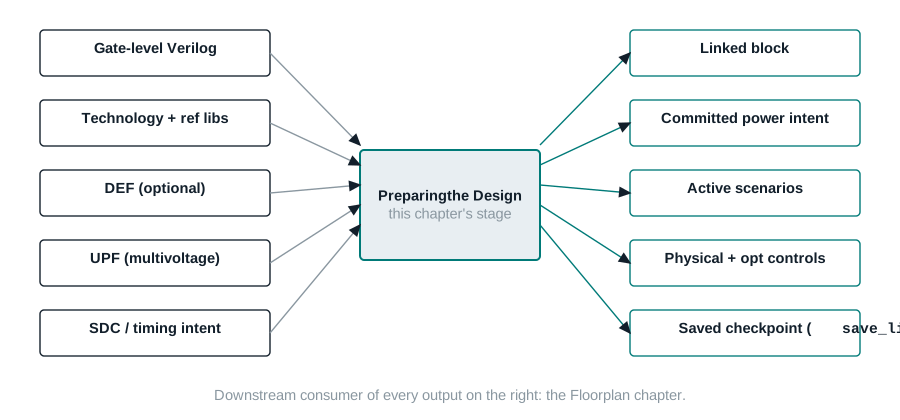
What enters, what must leave
| Enters this stage | Must leave this stage |
|---|---|
| Gate-level Verilog netlist(s) | A single current block, linked, with a resolved top module and no unexplained black boxes |
| Technology file and reference (cell) libraries | A reference library list bound to the block, with cell purposes and target-library subsets set where required |
| Optional floorplan DEF, or none yet | Whatever physical data exists is annotated and consistent; if no floorplan exists yet, that gap is explicit, not silent |
| UPF power intent (multivoltage only) | Power intent loaded and committed, with check_mv_design clean or its findings tracked |
| SDC-equivalent (Synopsys Design Constraints) timing intent, clocks, and constraints | Modes, corners, and scenarios defined, with the intended analysis roles active and unconstrained paths investigated |
| Early project assumptions about physical and optimization constraints | A first, named, and justified set of keepouts, blockages, preservation attributes, and routing-resource constraints |
What does not leave this stage: a floorplan shape, macro placement, or power network. Those belong to the next chapter, Floorplan. If a DEF file already carries floorplan information, this chapter shows you how to bring it in safely, but designing that floorplan from nothing is out of scope here.
What you should already be comfortable with
- Reading a gate-level Verilog netlist well enough to recognize a module, an instance, a port, and a net.
- The idea of a standard-cell library and a technology file, even if you have not yet used one inside a place-and-route tool.
- Basic Tcl (Tool Command Language): variables, lists, and running a command with options from a shell prompt. ICC2's shell,
icc2_shell, is a Tcl interpreter with design-specific commands added to it. - What setup and hold timing checks are, in outline. This chapter uses those terms but does not re-derive them; the Clock Tree Synthesis chapter goes deeper.
You do not need prior place-and-route tool experience. Where this chapter uses a term for the first time, it defines it before relying on it.
By the end of this chapter, you will be able to…
- Explain the difference between a design library, a block, and a reference library, and set the search path so that library resolution is deterministic.
- Import a gate-level netlist and a DEF floorplan, and verify what each import step actually changed using ICC2's own reports.
- Load, commit, and verify UPF power intent for a multivoltage design, and explain what changes when a design is single-voltage instead.
- Set up modes, corners, and scenarios well enough to know which combinations are active for which kind of analysis.
- Define keepout margins, placement blockages, and preservation attributes with the correct strength for each, and explain which flow stages honor each one.
- Configure the Early Data Check Manager to make a conscious choice, per check, between stopping the flow and tolerating a tracked gap.
- Produce and read the reports that prove the design is ready to floorplan, rather than assuming it from a lack of error messages.
Think of it as moving into an unfurnished apartment
Analogy. Imagine you are moving into a new apartment before you have furniture. You cannot just carry boxes in and call it done. You first confirm the lease (the technology and reference libraries), check which rooms exist and what their walls are made of (the linked block and its hierarchy), get the utilities turned on and verified — power, water, and their meters (power intent, committed and checked) — and only then do you start deciding which rooms are off-limits for the movers and which ones need extra padding on the corners (physical and optimization constraints). You do not need every piece of furniture placed yet; that is next chapter's job. What you need is a space where nothing unexpected will happen when the movers start working.
Engineering translation. "Confirming the lease" is creating or opening a design library with the right reference libraries and technology bound to it. "Checking the rooms" is reading and linking the Verilog netlist so every instance resolves to a real cell or a real subdesign, with no silent black boxes. "Utilities turned on and verified" is loading UPF, committing it, and running check_mv_design — or, for a single-voltage design, simply trusting the default power domain the tool created for you and connecting PG (power and ground) nets. "Rooms off-limits" is keepout margins and placement blockages; "extra padding" is preservation attributes like dont_touch that tell optimization to leave certain cells and nets alone.
Terms this chapter depends on
| Term | Plain-English meaning |
|---|---|
| Design library | An on-disk container (created or opened with create_lib / open_lib) that holds one or more blocks plus the technology data they share. |
| Block | A specific version of a design — top-level or a subdesign — inside a design library. This guide uses "block" for that specific object and "design" loosely for whatever is being processed. |
| Reference library | A library of cells (standard cells, macros, physical-only cells) that a design library points to but does not own. A design library can itself act as a reference library for something built on top of it. |
| Current library / current block | The library or block that unqualified commands operate on by default, set with current_lib / current_block. |
| Linking | The process of resolving every instance in the netlist to a real cell reference, either a library cell or a subdesign, and flagging what cannot be resolved. |
| Power intent (UPF) | A separate Unified Power Format file describing power domains, supply nets, and multivoltage strategy, loaded with load_upf and made authoritative with commit_upf. |
| Scenario | A named combination of one mode and one corner used for a specific kind of timing analysis and optimization. |
| Keepout margin | A region around a fixed object, inside or outside its boundary, where no other cell may be placed. |
| Placement blockage | A named rectangular or rectilinear region with a declared strength (hard, soft, partial, or category) that limits what can be placed inside it, and during which stages. |
dont_touch | An attribute that excludes a cell, net, module, or library cell from being modified or replaced during optimization. |
| Early Data Check Manager (EDC) | A subsystem that lets you set, per named check, whether an incomplete-data problem is treated strictly (stop) or leniently (continue and log). |
| Checkpoint | The saved state of a design library on disk, written with save_lib, that later stages and later engineers can reopen exactly as you left it. |
The Preparing the Design pipeline
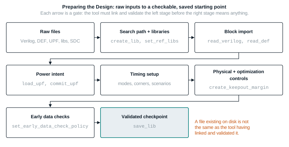
What comes in, what must go out
| Item | Owner | Format | Required? | Validation | Failure impact |
|---|---|---|---|---|---|
| Gate-level netlist | Synthesis / RTL (register-transfer level) team | Verilog | Required | read_verilog succeeds; top module identified; no unlinked references remain unexplained | Unresolved instances become black boxes that silently distort area, timing, and connectivity downstream |
| Technology file + reference libraries | Library / PDK team | Technology file, .ndm / Liberty-derived libraries, LEF (Library Exchange Format) where applicable | Required | report_ref_libs shows every reference library open and technology-bearing where expected | Missing or mis-bound libraries stop linking entirely, or worse, link against the wrong cell views |
| Floorplan DEF | Design planning / this engineer | DEF, ideally v5.8+ | Optional at this stage | read_def -syntax_only clean; check_duplicates -remove run after import | A DEF with unexpected site or track definitions can quietly redefine the placement area |
| UPF power intent | Power architecture team | UPF | Required for multivoltage designs only | commit_upf succeeds; report_mv_path shows expected associations; check_mv_design clean | Uncommitted or partially resolved power intent produces wrong or missing level shifters and isolation cells later |
| Timing intent (clocks, exceptions, I/O delays) | Timing / synthesis team | SDC-equivalent Tcl constraints | Required | Modes, corners, and scenarios defined; intended scenarios active; unconstrained endpoints investigated | Missing constraints optimize the wrong thing, or nothing, without any error message |
| Artifact | Consumer | Persistence | Handoff rule |
|---|---|---|---|
| Linked, saved block | Floorplan chapter | save_lib on disk | Never hand off an unsaved, in-memory-only state |
| Committed power intent | Every later stage that inserts or checks multivoltage cells | Stored in the block; exportable with save_upf | Re-run check_mv_design after any later netlist edit |
| Active scenarios | Placement, CTS (clock tree synthesis), routing, and signoff | Stored in the block | Document which scenarios are active for which analysis type (setup, hold, leakage, dynamic power) |
| Physical and optimization constraints | Placement and Optimization chapter | Stored in the block | Every constraint should be named and have a one-line reason a reviewer can check |
| Early data check policy log | Whole project, especially signoff | write_early_data_check_config output plus the issue register | Every tolerated check must appear in the issue register with an owner |
Before you open icc2_shell
- You know the absolute or relative locations of every input file, and you have a directory layout that will not require a fragile
search_path.Evidence: a written manifest listing each file and its path, checked into your working area. - You know whether this design is single-voltage or multivoltage, and if multivoltage, you have the UPF file in hand.Evidence: a one-line statement of voltage domains from the power architecture owner.
- You know which modes, corners, and scenarios this design is expected to have, even before you create them.Evidence: a scenario table from the timing owner, or your own draft of one.
- You know whether a floorplan DEF already exists for this block, or whether floorplanning is still ahead of you.Evidence: confirmation from design planning, one way or the other — not an assumption.
Building the foundation, one dependency at a time
The topics below are ordered so that each one only depends on what came before it. Skipping ahead usually still "works" in the sense that the shell accepts your commands — but the resulting design state will not mean what you think it means.
1. Flow boundary and the database mental model
ICC2 keeps your design as an in-memory database, organized as design libraries containing blocks, plus the reference libraries and technology data those blocks depend on. A block is a specific version of a design — the current top-level netlist, or a subdesign, at a specific point in the flow. Nothing you do to files on disk affects this in-memory database until you explicitly read it in; nothing you do to the in-memory database reaches disk until you explicitly save it.
This matters because the phrase "the design" is ambiguous in casual conversation but never ambiguous to the tool. When someone says "the design doesn't have that constraint," the precise question is: is the constraint missing from the file, missing from the current in-memory block, or present in memory but not yet saved? Each of those is a different bug with a different fix.
2. Tool start and reproducibility
Every ICC2 session starts from a working directory and a set of setup files you source or pass at invocation. Two things make a session reproducible: a deterministic search path (covered next), and a habit of capturing what you ran. A minimal run manifest is nothing more than a text file recording the tool version, the working directory, and the exact sequence of setup and command files you sourced, in order.
Relative paths are the most common source of "it worked on my machine." A relative path resolves against the working directory the shell happened to be started from, not against wherever your script file lives. If two engineers invoke the same script from two different directories, a relative path in that script can silently resolve to two different files.
3. Defining the search path
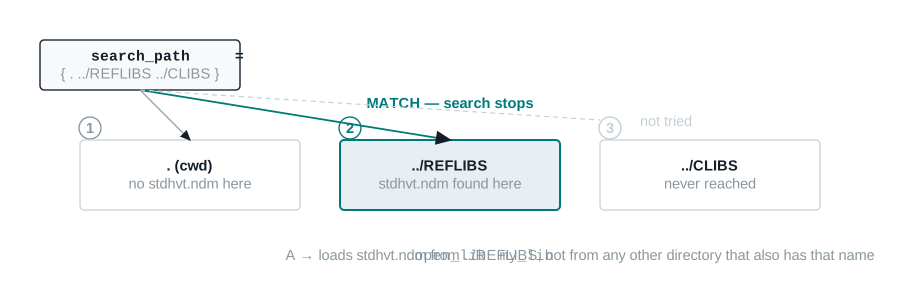
When ICC2 needs a file specified with a relative path or with no path, it searches the directories listed in the search_path Tcl variable, left to right, and uses the first match it finds. You set the whole list with set_app_var search_path {…}, or add to the front or back of the tool's default search path (the directory you invoked the tool from) with Tcl's lappend.
icc2_shell> lappend search_path ./mylibdir
Order is the whole point of this mechanism. If two directories in your search path both contain a file with the same name, the leftmost directory wins silently — there is no warning that a second candidate existed.
4. Design and reference libraries
A design library is a container for one or more blocks plus shared technology data. A reference library is a library of cells that a design library uses but does not own — standard cells, hard macros, and physical-only cells such as pads and fillers. A design library can itself serve as a reference library for whatever is built on top of it, which is exactly how hierarchical implementation composes blocks in a later chapter.
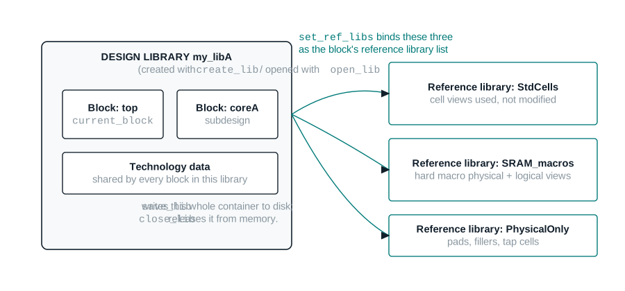
You create, open, query, save, and close a design library with create_lib, open_lib, current_lib, save_lib, and close_lib. Creating a library makes it the current library in memory only; nothing reaches disk until save_lib.
icc2_shell> create_lib ../my_lib_dir/my_libA
{my_libA}
icc2_shell> open_lib my_libA
/* loads the library and every reference library it points to */
{my_libA}
You specify the reference library list either at creation time, with the -ref_libs option of create_lib, or afterward with set_ref_libs. If a reference library moves, use set_ref_libs -rebind to re-resolve the paths against the current search_path. Note that rebinding the library's reference list does not automatically rebind blocks already loaded from it — use link_block -rebind for that.
5. Library readiness
Having a library bound is not the same as having a library that is safe to build with. Two checks matter before you move on: which library cells the tool is allowed to use, and whether those cells are physically legal to place given your technology's pin-access rules.
By default ICC2 can use every cell in every bound library for optimization and clock tree synthesis. Use set_lib_cell_purpose -include | -exclude to restrict specific cells to specific purposes (all, cts, hold, optimization, or none). A cell carrying a dont_use attribute is automatically excluded everywhere, equivalent to -include none.
icc2_shell> set_lib_cell_purpose -include none [get_lib_cells HVT_lib/CLK*]
icc2_shell> set_lib_cell_purpose -include cts   [get_lib_cells HVT_lib/CLK*]
Separately, you can restrict which library cells are eligible for specific blocks or hierarchies with set_target_library_subset, then enable the restriction with the opt.common.enable_target_library_subset_opt application option. This is how you keep a low-Vt library confined to one voltage-sensitive subblock instead of letting it leak into the rest of the chip.
The Pin Access Checker (PAC) utility is a separate, earlier-stage check aimed at library developers: it verifies that a cell's pins are physically reachable given real placement, legalization, and routing rules, using create_pin_check_lib and check_libcell_pin_access. As an implementation engineer you will not usually run PAC yourself, but you should recognize its vocabulary — pin accessibility — because a library that fails PAC in development will show up to you later as unexplained legalization displacement.
6. Import logical design
With the design library open and its reference libraries bound, you read the gate-level netlist with read_verilog. By default the tool creates a block in the current library, determines the top-level module as whichever module is not instantiated by anything else in the files you gave it, and uses that module's name as the block name. It also creates a default power domain for the block — the single-voltage starting point described in Setting up multivoltage designs below.
icc2_shell> read_verilog nimbus8_top.v nimbus8_core.v
/* top module auto-detected: the module nothing else instantiates */
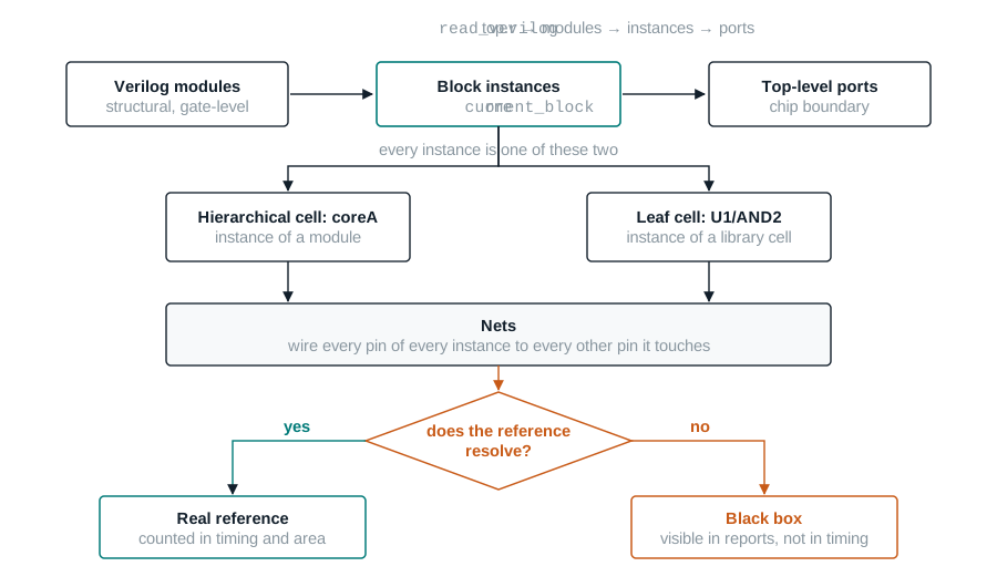
You manage blocks explicitly with create_block, open_block, current_block, save_block, and close_blocks. In most single-block sessions you will not touch these directly — read_verilog creates the block for you — but you need them the moment you work with more than one block in a library, which becomes routine in the Hierarchical Implementation chapter.
Rollback point: before you read in a netlist over an existing block, save the current library state if it is worth keeping. read_verilog into an already-open design is not allowed — the design must not already exist or be closed — which is itself a small safety rail against accidentally overwriting work.
7. Import or create physical context
A floorplan carries the core area and shape, port locations, macro locations and orientations, blockages, site rows, routing tracks, and any preroutes. If a floorplan already exists for your block — commonly handed off from an earlier project phase or a design-planning pass — you bring it in as a DEF file with read_def. If no floorplan exists yet, you defer that work entirely to the next chapter, Floorplan, which builds one from nothing.
icc2_shell> read_def nimbus8_core.def
By default read_def annotates the current block, preserves existing floorplan information rather than discarding it (incremental mode), and uses rule-based name matching so that small naming differences — hierarchical separators, bus notation — do not cause false mismatches between the DEF and the block. To discard existing floorplan data before applying a new DEF, use -no_incremental. To require exact name matches instead of rule-based matching, set the file.def.rule_based_name_matching application option to false.
Only a specific set of physical constraints are extracted from a DEF file: placement area, port locations, cell locations, placement blockages, site rows, routing tracks, placement bounds, routing blockages, and preroutes. Objects in the DEF that do not already exist in the block are ignored by default, except PG (power and ground) objects. Use -add_def_only_objects to allow the tool to create new cells, nets, or ports from DEF-only content when you explicitly want that.
8. Power intent and multivoltage readiness
Every block gets a power domain the moment it is read in. For a single-voltage design, that is the end of the story: read_verilog creates a default power domain covering the whole core area, and you move on. A multivoltage design replaces that default with real power domains, voltage areas, and supply connectivity, defined in a UPF file and made authoritative through a specific load-and-commit sequence.

commit_upf, that the single-voltage path does not need. Until that command succeeds, the power intent is text the tool has read but not yet trusted.The load-and-commit sequence is: read the UPF with load_upf; optionally read a Design Compiler name-mapping file with read_name_map if you are using the golden-UPF flow; optionally verify consistency and preview PG-conflict resolution with resolve_pg_nets -check_only; then commit with commit_upf, which performs global UPF consistency checks, resolves PG conflicts among the netlist, floorplan, and UPF specification, and associates power strategies with any multivoltage cells already present. Finally, confirm the associations with report_mv_path.
icc2_shell> load_upf nimbus8.upf
icc2_shell> commit_upf
icc2_shell> report_mv_path
Once power intent is committed, logical PG connections between supply nets and the power, ground, and tie-off pins on every cell must exist. Use connect_pg_net -automatic to derive connections from the UPF specification, or connect_pg_net -net NET_NAME [get_pins ...] for manual control. Single-voltage designs still need this step — the "UPF specification" they resolve against is just the default domain read_verilog created.
Multivoltage designs place power-domain cells inside voltage areas, defined with create_voltage_area -power_domains … -region …. A voltage area behaves like an exclusive move bound: cells in the domain must stay inside it, and everything else must stay out. Guard bands, set with the -guard_band option, add a hard keepout ring around the voltage area's effective boundary so that adjacent domains cannot short at the edge.
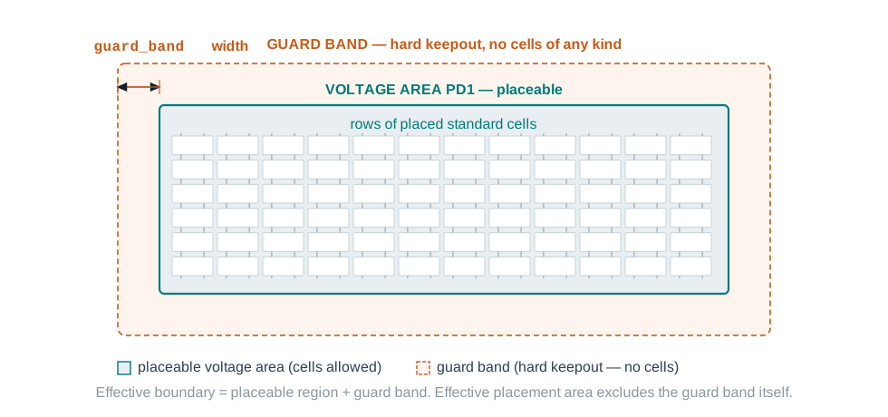
Finish with check_mv_design to verify the design has no multivoltage rule violations, and use the reporting commands — report_mv_design, report_mv_cells, report_voltage_areas, and related commands — to confirm the domains, voltage areas, and multivoltage cells are what you expect before moving on.
9. Timing setup: modes, corners, and scenarios
Timing constraints describe what your design must achieve, and clocks are the essential part of that description: everything else about a timing path is measured relative to when a clock edge arrives. When you define clocks, ICC2 automatically constrains the paths between the registers those clocks drive. You then layer exceptions — false paths, multicycle paths — and boundary constraints — input and output delays — on top of that default behavior.
A block can operate under different conditions — voltage, temperature — and in different functional modes. ICC2 represents each set of operating conditions as a corner, each functional mode as a mode, and a specific combination of the two, used for one purpose of timing analysis and optimization, as a scenario.
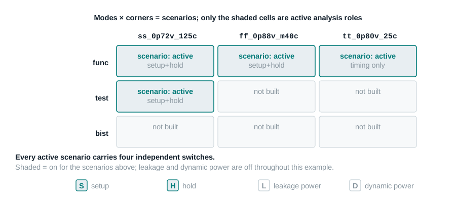
ICC2 performs on-chip variation (OCV) analysis by default: for a setup check it applies maximum delays to the launch clock path and data path and minimum delays to the capture clock path. For a hold check it reverses that, using minimum delays on the launch side and maximum on the capture side. You do not configure this behavior in this chapter — you only need to know it is happening so that a "surprising" number of paths reported later does not surprise you.
9a. Logical design rule constraints
Minimum capacitance, maximum capacitance, and maximum transition are technology-specific limits your design must respect regardless of timing, power, or area goals — the tool treats them as a higher priority than those optimization objectives. Library cells already carry technology-appropriate defaults; you tighten them with set_min_capacitance, set_max_capacitance, and set_max_transition, and remove a user override with the matching remove_* command. After optimization, report_constraints -max_transition and its siblings show remaining violations.
9b. Controlling clock-gate latencies
Before clock tree synthesis, ICC2 treats clocks as ideal — zero delay through the network — because real network delay is unknown until the tree exists. For a design with clock gating, that idealization hides a real asymmetry. The clock-network delay at a clock-gating cell differs from the delay at the registers it gates, which tightens the effective setup margin at the gating cell's enable input.
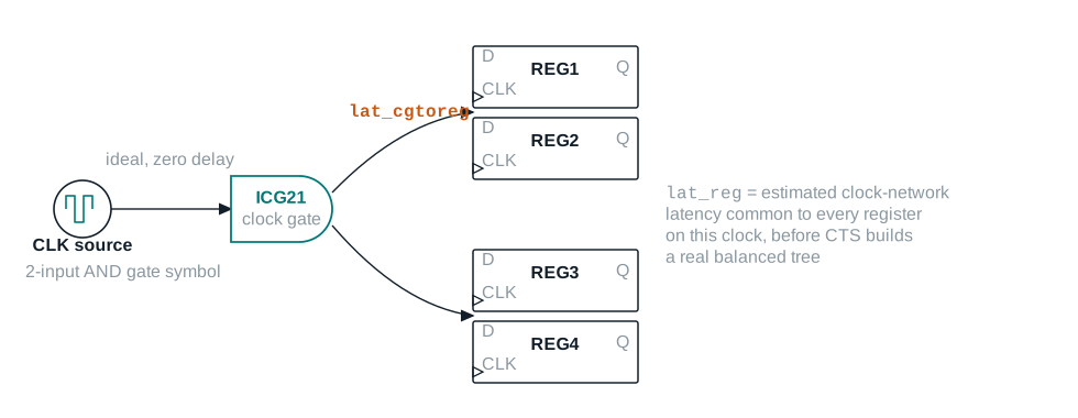
place_opt, which is more accurate than a hand-specified value because it responds to where cells actually land. Reach for set_clock_latency only where you need to override a specific gate's estimated delay, using the dont_estimate_clock_latency attribute on its clock pin to stop automatic estimation there.10. Physical constraints for placement and legalization
Four constraint families shape where cells may legally land, each with a different strength and a different set of stages that honor it. Getting the strength right matters as much as getting the geometry right.
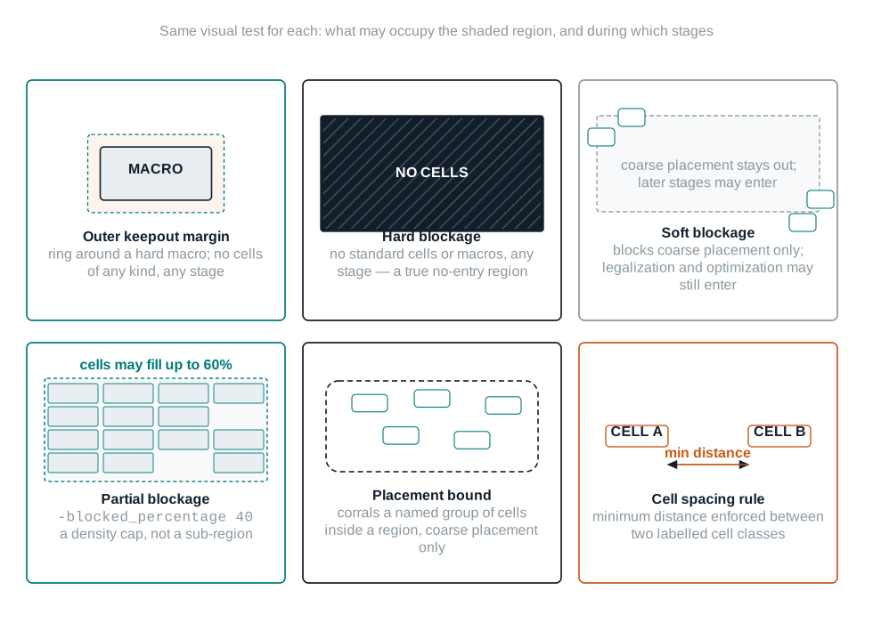
| Constraint | Command | Honored during |
|---|---|---|
| Outer / inner keepout margin | create_keepout_margin | Placement, legalization, optimization, CTS (hard by default) |
| Hard blockage | create_placement_blockage -type hard | Coarse placement, optimization, legalization |
| Hard macro blockage | create_placement_blockage -type hard_macro | Coarse placement, optimization, legalization — the only type hard-macro placement honors |
| Soft blockage | create_placement_blockage -type soft | Coarse placement only, unless place.coarse.enable_enhanced_soft_blockages is set |
| Partial blockage | create_placement_blockage -type partial -blocked_percentage N | Coarse placement only, as a density cap |
| Category / register / relative-placement blockages | -type category | register | rp_group | allow_rp_only | Coarse placement only |
icc2_shell> create_keepout_margin -outer {10 10 10 10} nimbus8_ddrphy
icc2_shell> create_placement_blockage -boundary {{120 75} {230 200}} -type hard_macro
11. Controlling the optimization of cells, nets, pins, and ports
Before any placement or optimization command runs, you decide what optimization is not allowed to touch. Four mechanisms cover almost every situation, and they compose in a specific precedence order.
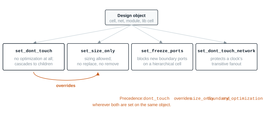
dont_touch is the strongest of the four and overrides size_only and boundary_optimization wherever both are set on the same object. Setting dont_touch on a hierarchical cell implies the same attribute on every cell beneath it — a child cannot opt back out.icc2_shell> set_dont_touch [get_cells U_DDR_PHY] true icc2_shell> set_size_only [get_cells U_CORE/reg_bank_*] true icc2_shell> set_dont_touch_network [get_clocks CPU_CLK] -clock_only
Two more controls round out this stage: set_auto_disable_drc_nets selectively turns off design rule checking on clock, constant, or scan nets where DRC (design rule checking) fixing would be counterproductive; and set_allow_new_cells false, alongside a create_voltage_area_rule -allow_new_cells false variant for voltage areas, stops optimization from inserting new cells into a hierarchical cell or domain you consider closed.
12. Preroute, power, and routing-resource setup
This section is a setup contract, not a routing tutorial — the Routing and Postroute Optimization chapter covers the router itself. What belongs here is telling optimization what resources it will have to work with before it starts using them.
Routing layer constraints. Set global minimum and maximum routing layers with set_ignored_layers -min_routing_layer -max_routing_layer, which by default acts as a soft constraint for routing and a hard constraint for RC estimation and congestion analysis. Net-specific overrides use set_routing_rule; clock-tree-specific layer constraints use set_clock_routing_rules, which can target a clock's root, internal, or sink nets separately. Set these before placement — they feed RC estimation and congestion analysis from the start, not only routing at the end.
icc2_shell> set_ignored_layers -min_routing_layer M2 -max_routing_layer M8
Preferred routing direction. Every routing layer needs a preferred direction. Cell libraries usually supply this, but you can set or override it per block with set_attribute [get_layers M5] routing_direction vertical.
Parasitic estimation. Two techniques improve how closely preroute optimization's RC estimates track the postroute result: global-route-layer-based (GRLB) estimation, enabled with opt.common.use_route_aware_estimation, and route-driven estimation (RDE), enabled with opt.common.enable_rde and automatically on by default below 16 nm. Pick one path and use it consistently through every preroute optimization step — mixing them across stages produces inconsistent RC assumptions from one command to the next.
Via ladders. A via ladder is a stacked via from a pin layer up into the routing layers, used on timing-critical or electromigration-sensitive pins. Define candidates per library pin with set_via_ladder_candidate, in priority order, then enable automatic insertion with opt.common.enable_via_ladder_insertion.
Power setup. If you plan dynamic-power-aware placement or optimization, annotate switching activity first — either read_saif or set_switching_activity — and enable the relevant scenario status with set_scenario_status -dynamic_power true or -leakage_power true. Without an annotated activity, the tool falls back to a default toggle rate propagated from primary inputs, which is a reasonable estimate, not a substitute for real activity when power is a hard goal.
13. Early data checks and strategy settings
Early in a design cycle, some of your data will be incomplete or wrong, and you will still need to make forward progress for exploration purposes. The Early Data Check Manager (EDC) is how you make that a deliberate decision instead of an accident. For each named check you choose a strict policy, which stops the flow with an error, or a lenient policy, which tolerates the failure, logs it, and continues.
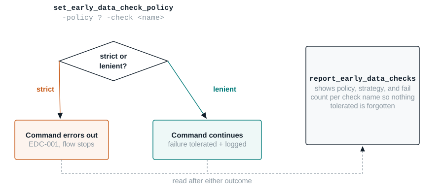
icc2_shell> set_early_data_check_policy -policy strict -check place.coarse.missing_scan_def
icc2_shell> create_placement
/* Error: No valid scan def found. Flow stops here by design. */
report_early_data_checks shows the policy, strategy, and fail count for each check. The companion command get_early_data_check_records returns a Tcl collection of violations for use in other commands; write_early_data_check_config saves your policy settings for reuse; and remove_early_data_check_records clears logged violations before another iteration.
Separately, mega-switch commands apply a coordinated bundle of settings across placement, legalization, routing, and extraction in one call. That is useful once you know your technology node or QoR priority: set_technology -node 7 applies advanced-node-specific defaults; set_hpc_options -core … -stage … applies settings tuned for a named high-performance core design at a specific flow stage; and set_qor_strategy -stage pnr -metric timing | leakage_power | total_power applies the setting bundle for a specific QoR priority. Use -report_only or -diff_only on these commands to see what they would change before you commit to them.
The commands worth knowing cold
Every card below follows the same eight-point shape, and every syntax line has been checked against the ICC2 Tcl command reference for this release. Where your installed release differs, trust man <command> over this page.
create_lib
Creates a new design library in memory.
- What it isAllocates a new design library, optionally bound to a technology file and a reference library list, and makes it the current library.
- Why you run itEvery block you read in has to live inside a design library; this is the first command in almost any fresh session.
- When in flowFirst, before
read_verilogorread_def. - Exact Tcl
icc2_shell> create_lib ../libs/nimbus8_lib \ -technology ../tech/nimbus8.tf \ -ref_libs {../libs/StdCells.ndm ../libs/SRAM_macros.ndm} - What ICC2 changesCreates the library in memory and sets it as the current library; nothing reaches disk until
save_lib. - What to read back — proof it took effect
current_libreturns the new library name;report_ref_libslists the bound reference libraries with*(open) and+(technology-bearing) flags. - TrapThe library name cannot contain a colon or a space — those characters delimit library and design names internally. A name collision with an existing file or directory on disk is a hard error, not a warning.
- If you skip itEvery later command that needs a current library errors immediately; there is no implicit default library to fall back on.
open_lib
Opens an existing design library for edit or read access.
- What it isLoads a previously saved design library into memory, along with every reference library it points to, and makes it the current library.
- Why you run itTo resume work on a design library saved in a previous session.
- When in flowStart of any session that continues earlier work, in place of
create_lib. - Exact Tcl
icc2_shell> open_lib ../libs/nimbus8_lib - What ICC2 changesLoads the library and its reference libraries into memory; design libraries default to edit mode, cell libraries default to read mode.
- What to read back
current_libconfirms the library is open and current; watch the information messages naming each reference library file loaded. - TrapExplicitly requesting edit mode on a cell library only succeeds with a downgrade warning — cell libraries in an implementation tool session are read-only regardless of what you ask for.
- If you skip itYou silently keep working in whatever library happened to be current before, which may not be the one you meant.
set_ref_libs
Sets or rebinds the reference library list for a design library.
- What it isSpecifies, replaces, or rebinds the reference libraries a design library points to, independent of
create_lib. - Why you run itTo change the reference library list after creation, or to repair a broken reference after a library moved on disk.
- When in flowAny time after
create_liboropen_lib, before you rely on cell resolution. - Exact Tcl
icc2_shell> set_app_var search_path {. ../REFLIBS ../CLIBS}
icc2_shell> set_ref_libs -rebind
- What ICC2 changesUpdates the library's reference library list; with
-rebind, re-resolves existing reference paths against the currentsearch_path. - What to read back
report_ref_libsafter the change, comparing paths against what you expected. - TrapRebinding the library's reference list does not rebind blocks already loaded from the old references. Use
link_block -rebindseparately for those. - If you skip itA moved or renamed reference library leaves the design library pointing at a path that no longer resolves, breaking every subsequent library-cell lookup.
read_verilog
Reads one or more gate-level Verilog files into a new block.
- What it isParses structural Verilog and builds a block whose top module is whichever module nothing else instantiates, unless you override it with
-top. - Why you run itIt is how the logical netlist enters ICC2's database in the first place.
- When in flowAfter the design library and reference libraries are ready.
- Exact Tcl
icc2_shell> read_verilog -design nimbus8_top nimbus8_top.v nimbus8_core.v - What ICC2 changesCreates a block in the current library, links what it can against bound reference libraries, and creates a default power domain for the block.
- What to read back
current_blockfor the block name; a linking or black-box report confirming every instance resolved to a real reference. - TrapReading into an already-open design is not allowed — the design must not already exist or be currently open, so a stray earlier
read_verilogin the same session can block a clean re-read. - If you skip itThere is no block, and nothing else in this chapter has an object to operate on.
read_def
Annotates floorplan and physical information from a DEF file onto a block.
- What it isImports placement area, port and cell locations, blockages, site rows, tracks, bounds, and preroutes from a DEF file onto the current or a named block.
- Why you run itTo reuse a floorplan that already exists instead of building one from nothing.
- When in flowAfter the block is linked, only if a floorplan already exists; otherwise this step waits for the Floorplan chapter.
- Exact Tcl
icc2_shell> read_def -syntax_only nimbus8_core.def
icc2_shell> read_def nimbus8_core.def
icc2_shell> check_duplicates -remove
- What ICC2 changesAnnotates the extracted physical constraints onto the block in incremental mode by default, preserving what already existed unless
-no_incrementalis used. - What to read backThe layout view in the GUI shows every extracted constraint automatically;
report_ignored_layersand floorplan reports confirm the numbers match what you expected. - TrapObjects in the DEF that do not already exist in the block are silently ignored unless you pass
-add_def_only_objects— a DEF built against a slightly different netlist can quietly drop data instead of erroring. - If you skip itThe block has no physical constraints at all; every placement-time command will either error or treat the whole core as open, unblocked space.
load_upf / commit_upf
Reads UPF power intent and makes it authoritative for the block.
- What it isA two-step sequence:
load_upfparses a UPF file's commands;commit_upfresolves PG conflicts and finalizes the power intent as complete. - Why you run itIt is the only supported path to a trustworthy multivoltage power domain and voltage area structure.
- When in flowAfter the block is linked, before defining voltage areas or inserting multivoltage cells.
- Exact Tcl
icc2_shell> load_upf nimbus8.upf
icc2_shell> commit_upf
icc2_shell> report_mv_path
- What ICC2 changes
commit_upfperforms global UPF consistency checks, resolves PG conflicts among netlist, floorplan, and UPF, and associates power strategies with existing multivoltage cells. - What to read back
report_mv_pathfor cell associations; a cleancheck_mv_designafterward. - TrapAfter
commit_upfsucceeds, almost every further UPF command is rejected. Fixing a mistake meansreset_upfand reloading, not patching in place. - If you skip itPower domains and voltage areas either do not exist or remain uncommitted text the tool will not rely on for multivoltage cell insertion.
connect_pg_net
Creates logical power and ground connections for every cell in the block.
- What it isConnects power, ground, and tie-off pins on leaf, hierarchical, and physical-only cells to the correct supply nets, in automatic or manual mode.
- Why you run itWithout it, cells exist with no logical PG connectivity at all, even though the UPF or default domain defines what those connections should be.
- When in flowAfter power intent is committed (multivoltage) or immediately after import (single-voltage).
- Exact Tcl
icc2_shell> connect_pg_net -automatic - What ICC2 changesDerives every PG net, pin, and tie-off connection from the power intent in automatic mode, creating supply nets that do not yet exist.
- What to read backA PG connectivity report showing no cell with unconnected power or ground pins.
- TrapFor single-voltage designs, you must run
resolve_pg_netsto resolve conflicts before connecting — multivoltage designs get this for free fromcommit_upf, single-voltage designs do not. - If you skip itPlacement and optimization can proceed on a design with no real power connectivity, which later shows up as an extraction or physical-verification failure far from its actual cause.
create_voltage_area
Defines the physical placement region for a power domain.
- What it isCreates a rectangular or rectilinear region, behaving like an exclusive move bound, that a power domain's cells must stay inside and every other cell must stay outside.
- Why you run itA power domain with no voltage area has intent but no physical home for its cells.
- When in flowAfter power intent is committed, before placement.
- Exact Tcl
icc2_shell> create_voltage_area -power_domains PD_ISP \ -region {{800 800} {1600 1600}} -guard_band {{3 3}} - What ICC2 changesCreates the voltage area shape and, if specified, its guard band; associates it with the named power domain(s).
- What to read back
report_voltage_areas -verbosefor the effective shape and guard band;check_mv_designfor placement-region conflicts. - TrapStacking order controls how overlapping voltage areas resolve. Define the outer area first and the inner area second, or the inner one is masked entirely.
- If you skip itMultivoltage cells have no legal placement region distinct from the rest of the core, and the placer cannot honor domain separation.
create_keepout_margin
Creates a hard or soft keepout ring around a fixed object.
- What it isDefines an outer or inner margin around a macro, hierarchical cell, or leaf cell in which no other cell may be placed.
- Why you run itFixed-cell boundaries are rarely safe to abut other cells against; the margin protects pin access and reduces net detouring.
- When in flowAfter the floorplan (or at minimum, macro locations) exists, before placement.
- Exact Tcl
icc2_shell> create_keepout_margin -outer {10 10 10 10} nimbus8_ddrphy - What ICC2 changesCreates a keepout region attached to the named object; hard by default, honored through placement, legalization, optimization, and CTS.
- What to read backThe layout view shows the margin visually;
get_attributeon the keepout object confirms the numeric margin applied. - TrapA margin derived with
-tracks_per_macro_pinis always hard, regardless of any-typesetting you pass — the derived-margin path ignores that option. - If you skip itCells can abut macro pins directly, and legalization can fail to find a legal home for cells the placer packed against a macro edge with no margin.
create_placement_blockage
Creates a named region that limits what may be placed inside it.
- What it isA rectangular or rectilinear region with a declared strength: hard, hard macro, soft, partial, category, register, or relative-placement variants.
- Why you run itTo reserve areas for later use (routing channels, future macros) or to steer placement density away from sensitive regions.
- When in flowAfter the floorplan exists, before placement.
- Exact Tcl
icc2_shell> create_placement_blockage -boundary {{10 20} {100 200}} \ -type partial -blocked_percentage 40 -name pad_ring_margin - What ICC2 changesCreates the named blockage with the specified strength; each call can only create one strength of blockage.
- What to read back
get_placement_blockagesfor a collection of what exists; the layout view for a visual sanity check against the floorplan. - TrapSoft, partial, category, register, and relative-placement blockages all bind coarse placement only. Assuming any of them constrain legalization or optimization is the single most common misreading of this command.
- If you skip itThe placer is free to use the whole core area uniformly, which is sometimes fine and sometimes exactly the problem, depending on what you meant to reserve.
set_dont_touch
Excludes a cell, net, module, or library cell from optimization.
- What it isSets the
dont_touchattribute, which prevents modification or replacement during optimization, and prevents ungrouping of the hierarchy it is set on. - Why you run itTo protect hand-placed or externally-verified logic — a hard macro's boundary logic, a pre-verified DFT block — from optimization's normal freedom to resize, replace, or restructure.
- When in flowBefore the first optimization command that could touch the protected object, typically during this stage.
- Exact Tcl
icc2_shell> set_dont_touch [get_cells U_DDR_PHY] true - What ICC2 changesSets the attribute on the object and, for hierarchical cells, implicitly on every cell beneath it.
- What to read back
report_dont_touchlists every object currently protected. - TrapA child cell cannot remove
dont_touchwhile its parent module still carries it — the attribute is not independently overridable per child. - If you skip itOptimization is free to resize, replace, or restructure logic you assumed was frozen, which is a common source of "why did this cell change" surprises late in a flow.
set_ignored_layers
Sets the global minimum and maximum routing layers for the block.
- What it isDeclares which routing layers are usable for RC estimation, congestion analysis, and (as a soft constraint by default) routing.
- Why you run itPreroute optimization's RC estimates and congestion analysis are only meaningful if they use the same layer range the router will eventually be told to respect.
- When in flowBefore placement, because it feeds RC estimation and congestion analysis from the start.
- Exact Tcl
icc2_shell> set_ignored_layers -min_routing_layer M2 -max_routing_layer M8 - What ICC2 changesMarks layers outside the range as fully blocked for RC and congestion estimation; the router treats the range as a soft constraint unless you set the layer-mode application options to
hard. - What to read back
report_ignored_layersfor the effective min/max layers and any additional RC-congestion-ignored layers. - TrapResetting one option (say,
-max_routing_layer) alone does not clear the other — each option only overrides its own setting, so a stale minimum from an earlier command can persist unnoticed. - If you skip itThe tool uses whatever the technology and library defaults imply, which is not always the layer range your package or stack-up actually intends for this block.
set_early_data_check_policy
Chooses strict or lenient handling for a named data-completeness check.
- What it isSets the policy — strict, lenient, or a related strategy — for one or more Early Data Check Manager checks, identified by name or wildcard pattern.
- Why you run itTo make a conscious, documented decision about which incomplete-data situations should stop the flow and which should be tolerated and tracked.
- When in flowBefore the command whose data checks you are configuring — typically early, as part of this stage's setup.
- Exact Tcl
icc2_shell> set_early_data_check_policy -policy lenient -check place.coarse.* - What ICC2 changesRecords the policy for the matching check names; subsequent commands consult this policy when the corresponding data-completeness situation occurs.
- What to read back
report_early_data_checksshows policy, strategy, and fail count per check name. - TrapA lenient policy silences the stop, not the underlying problem. Treat every tolerated check as an open item in your issue register, not a resolved one.
- If you skip itDefault policies apply, which may stop your exploratory flow on a check you would have preferred to tolerate — or worse, tolerate a check you needed to catch.
Nimbus‑8: preparing a teaching design end to end
Nimbus‑8 is a fictional SoC block used across this guide for continuity. Its numbers are teaching data, not measured silicon: 9.90 million standard cells, 72 SRAM macros, one DDR PHY hard macro, a 3.20 mm × 3.20 mm core, and four clocks — CPU at 1.60 GHz, NPU at 1.10 GHz, ISP at 800 MHz, and APB at 200 MHz. This chapter works the single-voltage path first, then shows the multivoltage delta on a smaller lab design, Lyra‑2, in the mini lab below.
Step 1 — directory manifest and search path
/* manifest: nimbus8/{rtl,libs,tech,def,upf,scripts} — checked into project area */
icc2_shell> set_app_var search_path {. ./libs ./tech ./def}
Step 2 — design library and reference libraries
icc2_shell> create_lib nimbus8_lib \
   -technology n8_tech.tf \
   -ref_libs {StdCells_rvt.ndm StdCells_lvt.ndm SRAM_macros.ndm PhysicalOnly.ndm}
{nimbus8_lib}
icc2_shell> report_ref_libs
Name          Path                    Location
------------------------------------------------------------
*+ StdCells_rvt  StdCells_rvt.ndm      /proj/nimbus8/libs/StdCells_rvt.ndm
*+ StdCells_lvt  StdCells_lvt.ndm      /proj/nimbus8/libs/StdCells_lvt.ndm
*  SRAM_macros   SRAM_macros.ndm       /proj/nimbus8/libs/SRAM_macros.ndm
*  PhysicalOnly  PhysicalOnly.ndm      /proj/nimbus8/libs/PhysicalOnly.ndm
"*" = open   "+" = has technology
Proof: every reference library shows *. If StdCells_rvt or StdCells_lvt were missing the +, technology resolution would be ambiguous later — investigate before continuing.
Step 3 — import the netlist
icc2_shell> read_verilog -design nimbus8_top nimbus8_top.v nimbus8_core.v nimbus8_uncore.v
/* top module auto-detected as nimbus8_top: nothing else instantiates it */
icc2_shell> current_block
{nimbus8_top}
Proof: a link or black-box report shows zero unresolved references against the 9.90 million-cell teaching count. Any nonzero black-box count is a stop-and-investigate signal, not a warning to note and continue past.
Step 4 — import the floorplan
icc2_shell> read_def -syntax_only nimbus8_core.def
icc2_shell> read_def nimbus8_core.def
icc2_shell> check_duplicates -remove
Proof: the layout view (see Visual inspection guide) shows a 3.20 mm × 3.20 mm core with 72 SRAM macros and the DDR PHY macro at their DEF-specified locations.
Step 5 — power intent (single-voltage path)
icc2_shell> connect_pg_net -automatic
/* single-voltage: resolves against the default domain read_verilog created */
Proof: a PG connectivity report shows zero cells with an unconnected power or ground pin.
Step 6 — timing setup
/* four clocks; two active teaching scenarios, explained before use */
/* func_ss_0p72v_125c: functional mode, slow-slow corner, 0.72V, 125C — worst-case setup */
/* func_ff_0p88v_m40c: functional mode, fast-fast corner, 0.88V, -40C — worst-case hold */
icc2_shell> set_scenario_status -active true func_ss_0p72v_125c
icc2_shell> set_scenario_status -active true -setup true func_ss_0p72v_125c
icc2_shell> set_scenario_status -active true -hold true func_ff_0p88v_m40c
Proof: report_scenarios shows both scenarios active with the intended setup/hold roles, and no unconstrained endpoints on the CPU, NPU, ISP, or APB clock domains.
Step 7 — physical and optimization constraints
icc2_shell> create_keepout_margin -outer {10 10 10 10} nimbus8_ddrphy
icc2_shell> create_placement_blockage -boundary {{0 0} {3200 60}} \
   -type hard -name pad_ring_bottom_margin
icc2_shell> set_dont_touch [get_cells nimbus8_ddrphy] true
icc2_shell> set_ignored_layers -min_routing_layer M2 -max_routing_layer M8
Proof: get_placement_blockages and the layout view both show the keepout and the pad-ring margin at the coordinates intended, and report_dont_touch lists the DDR PHY macro.
Step 8 — early data check policy
icc2_shell> set_early_data_check_policy -policy strict -check place.coarse.missing_scan_def
icc2_shell> set_early_data_check_policy -policy lenient -check mv.upf.*
/* lenient here only because Nimbus-8's first pass is deliberately single-voltage */
Step 9 — checkpoint
icc2_shell> save_lib nimbus8_lib
Saving library 'nimbus8_lib'
1
Checkpoint / rollback point: this saved library is the point every later chapter, and every failed experiment in this one, should be able to return to. Treat the return value 1 as confirmation, not decoration — a failed save returns a different, checkable status.
What to look for in the GUI
No screenshots are supplied here — your installed release's GUI layout will not match a static image for long, and the habit of looking is more durable than the habit of matching a picture. After each step above, open the layout view and check:
- After
read_def: does the core outline match the 3.20 mm × 3.20 mm teaching dimension, with 72 SRAM macros and the DDR PHY macro visible at fixed locations, not floating at the origin? - After defining keepout margins and blockages: do the shaded regions appear exactly where you specified them, with no overlap you did not intend?
- After
create_voltage_area(multivoltage path): does the voltage area's guard band render as a visually distinct ring outside the placeable region, not merged into it? - Zoom to a single macro's edge and confirm the keepout margin distance visually matches the numeric value you set — a margin defined in the wrong units is a classic, easy-to-miss mistake.
Reading proof, not just running commands
| Report | What it proves | Red flag to look for |
|---|---|---|
report_ref_libs | Every reference library is bound, open, and carries technology data where expected | A library missing the * (not open) or + (no technology) flag you expected |
Link / black-box status after read_verilog | Every instance resolved to a real cell or subdesign | Any nonzero black-box count against your expected cell total |
report_mv_path | Multivoltage cells associated correctly with their power strategies | Cells the tool reports it could not associate, with a stated cause |
report_voltage_areas -verbose | Voltage area shapes, guard bands, and stacking order match intent | An effective shape smaller or larger than the region you specified |
| Scenario status report | The scenarios you believe are active for setup, hold, leakage, or dynamic power actually are | A scenario you assumed active showing as inactive for the check type you care about |
report_constraints -max_transition and siblings | Logical design rule violations that predate any optimization | Violations on ports or pins you expected to already be clean from synthesis |
report_dont_touch | Preservation attributes landed on the objects you intended, and nowhere else | An object missing from the list that you were certain you protected |
report_ignored_layers | Global routing layer constraints match your technology stack-up intent | A minimum or maximum layer left at a tool default you never reviewed |
report_early_data_checks | Every data-completeness check has a policy you chose on purpose, and a fail count you can account for | A nonzero fail count with no matching entry in your issue register |
When something is wrong, start here
| Symptom | Likely cause | Where to look first |
|---|---|---|
| Cell resolves to the wrong library variant (e.g., RVT instead of LVT) | Search path or reference-library order puts the wrong library first | report_ref_libs order; search_path contents |
| Netlist reads in with no errors, but cell count is far below expectation | A subdesign's Verilog file was never included in the read_verilog file list | Black-box / unresolved-reference report |
commit_upf fails or reports unresolved PG conflicts | Netlist, floorplan, and UPF disagree about a supply net's existence or connectivity | resolve_pg_nets -check_only output run before committing |
A cell you marked dont_touch still changed during optimization | The attribute was set on the wrong object level, or after the optimization command already ran | report_dont_touch; command order in your script |
| Placement uses areas you meant to reserve with a soft or partial blockage | Soft and partial blockages only bind coarse placement, not legalization or optimization, by default | Blockage type and stage-applicability table in this chapter |
| A scenario you defined never seems to influence optimization | The scenario exists but was never set active for the analysis type you care about | Scenario status report for setup / hold / leakage / dynamic power flags |
| The flow stops with an Early Data Check error you did not expect | A strict policy applies to a check you assumed was covered by a broader lenient pattern | report_early_data_checks for the exact policy bound to that check name |
Site name mismatch error on read_def | DEF site names do not match the technology file's site names | -convert_sites option of read_def |
The Preparing the Design exit gate
This is the same checklist a careful reviewer would use before approving a handoff to Floorplan. Every item names its evidence; "looks fine" is not evidence.
- All intended references resolve.Evidence: zero unexplained black boxes in the post-
read_veriloglink report. - Top design and hierarchy match expectation.Evidence:
current_blockname and instance count match the design manifest. - No unexplained black boxes or unresolved references remain.Evidence: black-box report reviewed line by line, not just for a zero count.
- Units, technology, sites, layers, and routing directions are coherent.Evidence:
report_ref_libstechnology flags and layerrouting_directionattributes reviewed against the technology file. - Scenarios and clocks exist, and the intended analysis roles are active.Evidence: scenario status report showing setup/hold/leakage/dynamic-power flags matching the plan.
- Unconstrained paths are investigated.Evidence: an unconstrained-endpoints report with zero unexplained entries.
- UPF and power-domain checks pass, where applicable.Evidence:
check_mv_designclean, or every finding tracked in the issue register. - PG connectivity intent is understood.Evidence: PG connectivity report shows zero cells with unconnected power or ground pins.
- Physical constraints are present, scoped, and justified.Evidence: every keepout and blockage has a name and a one-line reason a reviewer can check.
- Cell availability, legal placement, and pin access checks are reviewed.Evidence:
set_lib_cell_purposeand target-library-subset settings documented against the plan. - Early data check results are resolved or formally tracked.Evidence:
report_early_data_checksfail count matches the issue register exactly. - Saved checkpoint, logs, reports, and manifest are reproducible.Evidence: a second engineer can
open_libyour saved checkpoint and reproduce the same reports.
Lab: Lyra‑2, a small multivoltage design
Nimbus‑8 is too large to hand-trace in a short lab. Lyra‑2 is a smaller teaching design used here specifically to make the single-voltage-to-multivoltage delta concrete: two power domains, PD_ALWAYS_ON and PD_SWITCHED, on a 0.60 mm × 0.60 mm core with roughly 40,000 standard cells. All numbers are synthetic.
Setup
- A design library with Lyra‑2's Verilog, reference libraries, and a
lyra2.upffile defining the two power domains. - A DEF file with a floorplan already defined, including a rectangular region intended for PD_SWITCHED.
Tasks
- Create the design library, import the netlist, and import the floorplan, following Steps 1–4 of the worked example.
- Load and commit the UPF, then confirm the associations with
report_mv_path. - Define a voltage area for PD_SWITCHED over the region reserved in the floorplan, with a guard band of 2 on every side.
- Run
check_mv_designand resolve or document every finding. - Save the checkpoint and write a one-paragraph handoff note as if for a reviewer who has not seen this lab.
Expected observations
The voltage area's effective placement region should be visibly smaller than the region you specified in -region, because the guard band eats into the effective boundary without shrinking the placeable area from the inside — recheck Power intent and multivoltage readiness if that distinction is not intuitive yet. check_mv_design on a first attempt commonly flags a PG connectivity gap if connect_pg_net was run before commit_upf instead of after; if you see that finding, it is expected, and fixing the command order is the task, not a tool bug.
Cleanup
Close the library with close_lib once you have confirmed the saved checkpoint reopens cleanly with open_lib in a fresh session. Do not leave two engineers' work sharing one open, unsaved library state.
25 questions worth being able to answer cold
Q1. What is the difference between a design library and a block?
A design library is the on-disk container; a block is a specific design version stored inside it.
- What is happening
- A single design library can hold a top-level block and several subdesign blocks, all sharing the same technology data and reference library list.
- The trap
- Saying "the library" when you mean "the block that is currently open" — they are related but not interchangeable terms.
- What is being tested
- Whether you have the container/content distinction straight before using either term precisely in a design review.
Q2. Why does search_path order matter?
The tool stops at the first match, so the leftmost directory containing a same-named file always wins, silently.
- What is happening
search_pathis searched left to right for any file given with a relative or missing path.- The trap
- Assuming a "more specific" or "more recent" directory automatically takes priority — only position in the list decides.
- What is being tested
- Whether you would think to check
search_pathorder before assuming a file is simply missing.
Q3. What does read_verilog use to determine the top module?
Whichever module in the input files is not instantiated by any other module, unless you override it with -top.
- What is happening
- The tool infers hierarchy from instantiation relationships across every file you passed to the same
read_verilogcall. - The trap
- Passing an incomplete file list can make the wrong module look "uninstantiated" and get picked as top by accident.
- What is being tested
- Understanding that top-module detection is a consequence of your file list, not an independent fact about the design.
Q4. What is the difference between a hard and a soft placement blockage?
Hard blockages are honored through coarse placement, optimization, and legalization; soft blockages only bind coarse placement.
- What is happening
- ICC2 defines several blockage strengths precisely so different stages of the flow can be told different things about the same region.
- The trap
- Using a soft blockage to permanently reserve an area, then being surprised when legalization places cells there anyway.
- What is being tested
- Whether you know which stages each blockage type actually restricts, not just that "a blockage keeps cells out."
Q5. What must happen before UPF power intent can be trusted?
It must be committed with commit_upf, not just loaded with load_upf.
- What is happening
commit_upfresolves PG conflicts and finalizes power domain and strategy associations; before that, the UPF is parsed but not authoritative.- The trap
- Treating a successful
load_upfas proof the power intent is ready to use downstream. - What is being tested
- The load-versus-commit distinction, which is one of the most consequential two-step sequences in this chapter.
Q6. What is a scenario?
A named combination of one mode and one corner, used for a specific kind of timing analysis and optimization.
- What is happening
- Modes represent functional states, corners represent operating conditions; a scenario is the intersection used for one analysis purpose.
- The trap
- Assuming every mode-corner combination automatically exists as a scenario — only the ones you define do.
- What is being tested
- Basic vocabulary needed before any conversation about timing setup makes sense.
Q7. What does set_dont_touch actually prevent?
Modification or replacement during optimization, and it prevents the hierarchy it is set on from being ungrouped.
- What is happening
- The attribute cascades: setting it on a hierarchical cell implies it on every cell beneath that hierarchy.
- The trap
- Expecting to selectively remove
dont_touchfrom one child cell while the parent module still carries it — that is not supported. - What is being tested
- Whether you understand the cascading, not just the existence, of this attribute.
Q8. Why run read_def -syntax_only before the real read_def?
To check the DEF file's correctness and integrity without annotating anything onto the block, so a bad file cannot corrupt your current state.
- What is happening
- Check-only mode reports diagnostics but performs no annotation, leaving you free to fix the file and retry.
- The trap
- Skipping this step on a DEF from an unfamiliar source and only discovering a problem after floorplan data has already been annotated.
- What is being tested
- Defensive habits around unverified input files, not just knowledge of the flag's existence.
Q9. Why does connect_pg_net behave differently for single-voltage versus multivoltage designs?
Multivoltage designs get PG conflicts resolved automatically by commit_upf; single-voltage designs need an explicit resolve_pg_nets pass first.
- What is happening
- A single-voltage design's "UPF specification" is just the default power domain
read_verilogcreated, which was never run through the multivoltage commit sequence. - The trap
- Copying a multivoltage setup script onto a single-voltage design and expecting the same conflict resolution to have already happened.
- What is being tested
- Whether the single-voltage path is understood as a real, distinct path, not a degenerate case of the multivoltage one.
Q10. What happens if two voltage areas' shapes overlap?
Stacking order decides: the last-defined shape wins the overlapped region, and the tool does not remove either shape, only reinterprets the overlap.
- What is happening
- For a nested voltage area to render correctly, the outer area must be defined first so the inner area's shape ends up on top.
- The trap
- Defining the inner (smaller) voltage area first, which masks it entirely under the outer shape.
- What is being tested
- Correct mental model of "resolve," not "merge," for overlapping shapes from different voltage areas.
Q11. What is the difference between a voltage area's effective boundary and its effective placement area?
The effective boundary includes the guard band; the effective placement area excludes it.
- What is happening
- A guard band is a keepout ring attached to a voltage area shape, not additional placeable space.
- The trap
- Sizing a voltage area's
-regionas if the guard band width will be added on top of the placeable area you specified, rather than eaten from outside it. - What is being tested
- Precision about which of two closely related terms a given number describes.
Q12. Why might set_max_capacitance not be the right tool to bound fanout?
Because maximum fanout is not honored by ICC2 as a design rule at all; you need the opt.common.max_fanout application option, which is a soft optimization goal instead.
- What is happening
- Capacitance and transition are real design rule constraints with high optimization priority; fanout is handled as a separate, softer mechanism.
- The trap
- Assuming every synthesis-familiar design rule carries the same enforcement strength inside ICC2.
- What is being tested
- Whether prior synthesis-tool assumptions get carried over uncritically.
Q13. Why does the tool estimate clock-gate latency automatically, and when would you turn that off?
Because estimated latency responds to where cells actually land and is more accurate than a static, hand-specified value; you turn it off per clock-gating cell with dont_estimate_clock_latency when you need to override a specific gate.
- What is happening
- Integrated estimation runs throughout
place_opt, updating as placement and multibit banking change; user-specified values do not update themselves. - The trap
- Disabling estimation broadly "to be safe," which throws away accuracy for every clock gate instead of just the one you had a specific reason to override.
- What is being tested
- Judgment about scoping an override narrowly instead of defaulting to the blunt, global option.
Q14. What is the practical difference between the global and net-specific routing layer constraints?
set_ignored_layers sets a block-wide default; set_routing_rule overrides that default for specific nets, and net-specific constraints win when both apply.
- What is happening
- Net-specific minimum layers default to a soft constraint and net-specific maximum layers default to a hard constraint, independently configurable.
- The trap
- Setting a net-specific constraint and assuming it is exactly as strict, by default, as the global one.
- What is being tested
- Awareness that "more specific" constraints in ICC2 do not automatically inherit the strength of the general one they override.
Q15. Why should routing layer constraints be set before placement rather than just before routing?
Because they feed RC estimation and congestion analysis, which influence placement decisions long before actual routing happens.
- What is happening
- Preroute optimization relies on RC estimates that are only meaningful if they reflect the same layer range the router will eventually use.
- The trap
- Treating routing-resource setup as a "routing chapter" concern and leaving it at tool defaults through placement.
- What is being tested
- Whether the reader sees this chapter's setup work as feeding forward into stages beyond the next one.
Q16. What does a lenient Early Data Check policy actually do to a failing check?
It tolerates the failure and lets the flow continue, while still logging the violation for later review.
- What is happening
- The check still runs and still fails; only the tool's response — stop versus continue — changes with policy.
- The trap
- Treating "lenient" as "the check no longer applies," rather than "the check's failure is now tracked instead of blocking."
- What is being tested
- Whether tolerated is confused with resolved.
Q17. Two engineers on the same project get different open_lib results for library cell resolution. What do you check first?
- What is happening
- The most common cause is a difference in each engineer's effective
search_pathor working directory at invocation time, resolving a relative reference library path differently for each. - The trap
- Assuming a data corruption or tool-version issue before checking the mundane, and far more common, path-resolution explanation.
- What is being tested
- Whether reproducibility habits from earlier in the chapter get applied under real debugging pressure.
- Verified Tcl snippet
icc2_shell> report_ref_libs
Q18. After read_verilog, the block's cell count is roughly 15% lower than the synthesis report claimed. Walk through your triage.
- What is happening
- First check the black-box / unresolved-reference report, since a missing subdesign file is the most common cause of a cell-count shortfall with no hard error.
- The trap
- Re-running
read_verilogrepeatedly with the same file list, hoping for a different result, instead of comparing the file list against the synthesis manifest. - What is being tested
- Systematic triage order: check the report that directly explains the symptom before touching anything else.
Q19. commit_upf fails with a PG conflict you did not expect. What do you do before trying again?
- What is happening
- Run
resolve_pg_nets -check_onlyfirst to see exactly what the tool would change, rather than committing blind and hoping the automatic resolution matches your intent. - The trap
- Repeatedly re-running
commit_upfwith small unrelated changes, instead of reading what the preview check actually reports. - What is being tested
- Using the diagnostic command that exists specifically for this situation, instead of trial and error.
Q20. A reviewer asks you to prove that a specific macro's keepout margin is actually in effect, not just defined in your script. What do you show them?
- What is happening
- A command in a script proves intent, not effect. Show
get_attributeon the keepout object for the numeric margin, and the layout view for a visual confirmation at the macro's actual location. - The trap
- Pointing at the script line that created the margin as if that alone were proof it took effect on the current, saved design state.
- What is being tested
- The proof-over-opinion discipline this chapter is built around.
Q21. A block you marked entirely dont_touch still shows changed cells after place_opt. What are the two most likely explanations?
- What is happening
- Either the attribute was set on the wrong object — a subset of cells rather than the enclosing hierarchical cell — or it was set after
place_opthad already run once in the same session. - The trap
- Assuming the tool ignored the attribute, rather than checking whether the attribute was actually applied to the objects that changed.
- What is being tested
- Diagnosing your own script's command order and object scope before suspecting the tool.
Q22. Your Early Data Check log shows three tolerated checks, but your project's issue register only lists one. What is the actual problem, and what do you fix?
- What is happening
- The process gap, not the tool: two tolerated findings were never transcribed into the tracked register, meaning they have no owner and no target date.
- The trap
- Treating this as a tooling bug to investigate rather than a documentation discipline failure to correct immediately.
- What is being tested
- Whether the reader treats the issue register as load-bearing, not optional paperwork.
Q23. When would you deliberately choose a lenient Early Data Check policy for a check most teams would leave strict?
- What is happening
- Early in a design cycle, with exploration as the explicit goal — for instance a first-pass placement to gauge congestion before SCANDEF exists — a lenient policy on scan-related checks lets you get useful directional data without waiting on a DFT deliverable that is not the bottleneck for the question you are asking.
- The trap
- Presenting exploration-mode results as if they carried the same confidence as a strict, fully-checked run, to an audience that was not told which policy was in effect.
- What is being tested
- Judgment about matching check strictness to the actual purpose of a given run, and communicating that choice honestly.
Q24. How would you decide between GRLB and RDE for preroute parasitic estimation on a new technology node?
- What is happening
- Below 16 nm, RDE is enabled by default because per-unit resistance variation across layers is usually significant enough to justify its extra runtime; above that, GRLB's lighter-weight, global-route-layer-based estimate is often sufficient. The deciding factor is whether your specific stack-up shows meaningful per-layer resistance variation, which you can check directly rather than assuming from node number alone.
- The trap
- Mixing the two techniques across different stages of the same flow, producing preroute RC assumptions that are inconsistent from one optimization command to the next.
- What is being tested
- Whether a default is understood as a starting heuristic to verify against your actual stack-up, not a rule to apply unexamined.
Q25. A junior engineer asks why this chapter insists on so many separate "proof" reports instead of trusting a clean run with no errors. How do you answer?
- What is happening
- ICC2, like most large EDA tools, distinguishes a fatal error from a silently-accepted default or a partially-satisfied intent. A clean return code proves the tool did not refuse your command; it does not prove the command did what you meant. The reports exist because "no errors" and "correct" are different claims, and the gap between them is exactly where multi-week debugging sessions three stages later come from.
- The trap
- Answering only with "because the guide says so," instead of being able to name a concrete failure mode — a black box, a wrong-strength blockage, an inactive scenario — that a clean run would not have caught.
- What is being tested
- Whether the engineer can teach the underlying principle, not just cite the checklist.
Twelve facts worth having cold
create_lib vs. open_libcreate_lib makes a new library in memory; open_lib loads a previously saved one from disk. Neither reaches disk itself — only save_lib does.search_path resolution orderread_verilog top-module rule-top. An incomplete file list can make the wrong module look uninstantiated.load_upf vs. commit_upfload_upf parses UPF text; commit_upf resolves PG conflicts and makes the power intent authoritative. Only after commit is it trustworthy.commit_upfreset_upf and reload — you cannot patch in place.dont_touch cascadeopt.common.max_fanout application option, a soft optimization goal.set_ignored_layers, soft for routing but hard for RC estimation and congestion analysis by default. Set before placement, not just before routing.Terms used in this chapter
- Black box
- An instance in the netlist whose reference could not be resolved to a real library cell or subdesign, treated as an opaque placeholder.
- Checkpoint
- A saved, reopenable state of a design library on disk, written with
save_lib. - Corner
- A named set of operating conditions — voltage, temperature, process — used in timing analysis.
- Current library / current block
- The library or block that unqualified commands act on by default.
- DEF
- Design Exchange Format; a standard file format carrying physical floorplan and layout information.
- Design library
- An on-disk container for one or more blocks and their shared technology data.
- Early Data Check Manager (EDC)
- The subsystem that lets you set a strict or lenient policy per named data-completeness check.
- Guard band
- A hard keepout ring attached to a voltage area's boundary, included in its effective boundary but excluded from its placeable area.
- Keepout margin
- A region, inner or outer, around a fixed object in which no other cell may be placed.
- Linking
- Resolving every instance in a netlist to a real cell reference and flagging what cannot be resolved.
- Mode
- A named functional operating state of the design, used together with a corner to define a scenario.
- Placement blockage
- A named region with a declared strength (hard, soft, partial, category, and related variants) limiting what may be placed inside it.
- Power domain
- A logical grouping of cells sharing the same supply and power state, defined in UPF for multivoltage designs.
- Reference library
- A library of cells that a design library points to and uses, but does not own.
- Scenario
- A named combination of one mode and one corner, used for a specific type of timing analysis and optimization.
- Search path
- The ordered list of directories, held in the
search_pathTcl variable, the tool searches for relative or unqualified file names. - UPF
- Unified Power Format; the file format carrying power intent — domains, supplies, and multivoltage strategy.
- Voltage area
- A physical placement region associated with one or more power domains, behaving like an exclusive move bound.
Test yourself before moving on
- You have two reference libraries with a cell of the same name in different directories, both listed in
search_path. Which one does the tool use, and how would you confirm it? - Explain, in one sentence each, the difference between a hard blockage, a soft blockage, and a partial blockage.
- Why is
connect_pg_nethandled differently for single-voltage and multivoltage designs? - A colleague sets a keepout margin on a hard macro using
-tracks_per_macro_pinand also passes-type soft. What actually happens, and why? - Name two application options mentioned in this chapter that control routing-layer constraint strength, and state what each one's default constraint strength is.
- Why does this chapter insist that a lenient Early Data Check policy still requires an entry in the issue register?
Answers
- The library found first in
search_path, scanning left to right. Confirm withreport_ref_libs, checking the path resolved for each library name. - Hard: honored through placement, legalization, optimization, and CTS. Soft: honored during coarse placement only, by default. Partial: a density cap during coarse placement only, with no effect on legalization or optimization.
- Multivoltage designs get PG conflicts resolved automatically as part of
commit_upf; single-voltage designs never run that commit sequence, so they need an explicitresolve_pg_netspass first. - The derived margin from
-tracks_per_macro_pinis always hard; the-type softsetting is ignored for a derived margin on a hard macro. route.common.global_min_layer_modeandroute.common.global_max_layer_mode, both defaulting to a soft constraint for routing unless set tohardorallow_pin_connection.- Because "lenient" changes the tool's response to a failing check, not the underlying data problem. Without a tracked, owned entry, a deliberately tolerated gap quietly becomes a forgotten one.
What to carry forward
| Topic | Fact worth carrying forward |
|---|---|
| Libraries | A file existing on disk is not the same as the tool having linked and validated it — verify with reports, not silence. |
| Import | Top-module detection and black-box status both depend on your exact file list; check both explicitly after every read_verilog. |
| Power intent | UPF is not authoritative until commit_upf succeeds, and it cannot be patched afterward without reset_upf. |
| Scenarios | Existing and active are different things, and active is itself split by purpose: setup, hold, leakage, dynamic power. |
| Physical constraints | Strength (hard, soft, partial) determines which stages honor a constraint, not just its geometry. |
| Optimization controls | dont_touch cascades and outranks size_only; scope it deliberately. |
| Early data checks | Every tolerated check needs an owner in a tracked issue register, or it will be forgotten. |
Before you call this stage done
This is the same twelve-item exit gate from earlier in this chapter, repeated here as the final gate before handoff. See Stage completion checklist for the full evidence requirements attached to each item.
- All intended references resolve, with zero unexplained black boxes.
- Top design and hierarchy match the design manifest.
- Units, technology, sites, layers, and routing directions are coherent with the technology file.
- Scenarios and clocks exist, with intended analysis roles active.
- Unconstrained paths are investigated, not merely noticed.
- UPF and power-domain checks pass, or every finding is tracked.
- PG connectivity is complete and understood.
- Physical constraints are named, scoped, and justified.
- Cell availability, legal placement, and pin access are reviewed.
- Early data check results are resolved or formally tracked in the issue register.
- A saved checkpoint, with logs, reports, and manifest, reproduces cleanly for a second engineer.
Last word and bridge to Floorplan
Everything in this chapter was about proving a starting point, not building anything visible. That can feel unsatisfying — there is no picture of a chip to show for it yet. But every later chapter in this guide spends less time fighting mysterious failures in direct proportion to how rigorously this one was done. When a clock tree three chapters from now estimates a strange latency, or a macro keeps landing somewhere unexpected during placement, the first productive move is almost always back here: is the library resolution really what I think it is, is the power intent really committed, is the scenario really active.
The next chapter, Floorplan, picks up exactly where this one leaves off: a linked, checkable block with no shape yet. It covers core and die geometry, rows and tracks, macro placement, power planning interfaces, I/O and pin assignment, and the utilization arithmetic that turns a target density into an achievable one.