Detailed Design Analysis
Floorplan in ICC2: A Mentor Guide
How a linked, checkable block becomes a die with rows, tracks, placed macros, a compiled power network, and assigned pins — taught the way a senior engineer would explain it at the whiteboard.
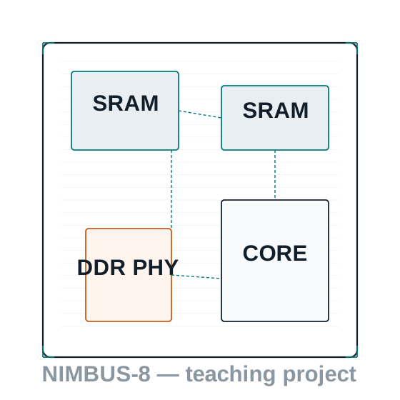
What you will be able to do after this chapter
By the end of this chapter you will be able to take a linked, checkable ICC2 block with no shape at all, and turn it into a die with a legal core, rows, and routing tracks; hard macros placed where a reviewer would expect them; a compiled power network; and pins assigned on the right sides, in the right order — and you will be able to prove each of those claims with the tool's own reports, not your impression of the layout view.
Concretely, you will be able to: create an initial floorplan with initialize_floorplan and explain what "core" and "die" mean as distinct, related boundaries; define rows and routing tracks and tell a legal site grid from an illegal one; place hard macros relative to one another with a named, reproducible offset instead of dragging them by eye; reserve space with the correct blockage strength for the stage you actually need to affect; compile a first power network and insert a power switch into a switched domain; assign block-level pins with defensible side, spacing, and layer rules; and compute utilization the way the tool computes it, not by eyeballing a picture.
None of this is about memorizing flags. It is about building the same mental model of "the floorplan is ready" that a design planning lead uses when deciding whether a block is safe to hand to placement — so that when placement congestion or a routing DRC shows up two stages later, you already know which floorplan decision to go back and question first.
Why this stage matters in the full flow
A floorplan is the one decision in the whole flow that almost nothing downstream can cleanly undo. Placement can be re-run. Clock tree synthesis can be re-balanced. Routing can be re-attempted with different effort. But a die that is too small for its macros, a macro placed against the wrong edge, or a power ring that leaves a corner starved is a geometry problem, and geometry problems propagate forward as congestion, timing closure difficulty, and IR drop — not as a clean error message at the stage that actually caused them.
This is also the first stage in this guide that produces something you can look at and be wrong about. A floorplan that looks reasonable in the layout view can still have macros placed without a real keepout margin, rows that do not actually align to the site grid at every macro edge, or a power network that is topologically fine but electrically thin in one quadrant. The habit this chapter builds — report before opinion — matters more here than anywhere so far, because floorplan mistakes are the ones a whiteboard sketch cannot catch.
What enters, what must leave
| Enters this stage | Must leave this stage |
|---|---|
| A linked, saved block with no floorplan shape (or a DEF-derived shape awaiting validation) | A die with a legal core, rows, and routing tracks, validated against the site grid |
| Hard macros in the netlist with no placement | Every hard macro placed, keepout-protected, and legal against its neighbors |
| Committed power intent (multivoltage) or a default power domain (single-voltage) | A compiled power network: rings, mesh, rails, and switches where a domain calls for them |
| Block-level pin intent (sides, layers, spacing, bundles) from the interface specification | Pins assigned to real physical locations, consistent with that intent |
| A target core utilization from the design planning owner | An achieved utilization figure the tool computed, not an estimate |
What does not leave this stage: standard cells placed, a clock tree, or detailed routing. Those belong to Placement and Optimization, Clock Tree Synthesis, and Routing, in that order. This chapter's exit gate is a shape the placer can trust, not a placed design.
What you should already be comfortable with
- Everything from Preparing the Design: a linked block, committed power intent where applicable, and a first set of physical and optimization constraints.
- Basic geometry: rectangles, offsets, and the idea of a coordinate grid with an origin at the lower-left.
- What a hard macro is — a pre-designed, fixed-shape block such as an SRAM or a PHY — as distinct from a standard cell.
- Basic Tcl, as used throughout this guide: variables, lists, and running a command with options from
icc2_shell.
You do not need prior floorplanning experience. Where this chapter uses a term for the first time, it defines it before relying on it.
By the end of this chapter, you will be able to…
- Explain the difference between the die boundary and the core boundary, and create an initial floorplan with
initialize_floorplanusing either as the control reference. - Define rows and routing tracks, and use
report_tracksto confirm what a track command actually created. - Distinguish channeled, abutted, and narrow-channel floorplan styles, and say what each one costs and buys you.
- Place a hard macro relative to another object with
set_macro_relative_location, and run floorplan-stage placement withcreate_placement -floorplan. - Choose the correct placement blockage strength for the stage you actually need to affect, and explain why "it shows up in the layout view" is not proof a blockage is doing what you think.
- Compile a first power network with
compile_pgand insert a power switch into a switched domain withcreate_power_switch. - Set block-level pin constraints and place pins with a defensible, reviewable rationale for every side, layer, and spacing choice.
- Compute achieved core utilization the way the tool computes it, and use
modify_die_areato correct a die that misses its target.
Think of it as laying out an unfurnished apartment's floor plan
Analogy. In the last chapter you confirmed the lease and checked the utilities. Now you actually draw the floor plan: where the walls go (the die and core boundary), where the floorboards run (rows and tracks — the grid everything else will snap to), where the built-in furniture goes that cannot move once installed (hard macros — the SRAM and DDR PHY), where the electrical wiring and breaker panel go (the power network), and where the doors and windows are cut into the walls (pins). You still are not moving in the everyday furniture — the standard cells — that is next chapter's job. What you need here is a floor plan a contractor could bid on without guessing.
Engineering translation. "Drawing the walls" is initialize_floorplan, choosing whether you are dimensioning the core or the die. "Floorboards" is create_track and derive_tracks, which must align to the site grid the technology file defines. "Built-in furniture" is macro placement, most defensibly done with set_macro_relative_location so a second engineer can see exactly why a macro sits where it does. "Wiring" is compile_pg and, for switched domains, create_power_switch. "Doors and windows" is pin assignment with set_block_pin_constraints and place_pins.
Terms this chapter depends on
| Term | Plain-English meaning |
|---|---|
| Die boundary | The outer physical edge of the chip, including any margin reserved for I/O pads or a pad ring. |
| Core boundary | The inner boundary that holds standard cells and macros, typically inset from the die by a core offset. |
| Site array / row | The grid of legal standard-cell placement sites, laid out as horizontal rows across the core. |
| Routing track | A line on a routing layer, at a defined pitch, that wires on that layer are expected to align to. |
| Channeled / abutted / narrow-channel floorplan | Three floorplan styles distinguished by whether space is left between blocks for top-level cells and routing. |
| Hard macro | A pre-designed, fixed-shape physical block, such as an SRAM instance or the DDR PHY, that placement cannot resize or restructure. |
| Relative placement constraint | A rule that fixes one macro's position as an offset from a named anchor object, instead of an absolute coordinate. |
| Placement blockage | A named region with a declared strength that limits what can be placed inside it, and during which stages. |
| Power ring / mesh / rail | The three tiers of a compiled power network: a ring around the core perimeter, a coarser mesh crossing the interior, and fine rails feeding standard cells directly. |
| Power switch | A cell inserted between an always-on supply and a switched domain's rail, turned on and off by a control signal. |
| Block pin constraint | A rule restricting which sides, layers, and spacing a block's or design's pins may use. |
| Core utilization | The fraction of the core area actually occupied by standard-cell and macro area, computed from real geometry, not assumed. |
The Floorplan pipeline
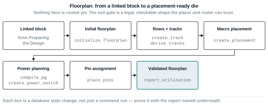
What comes in, what must go out
| Item | Owner | Format | Required? | Validation | Failure impact |
|---|---|---|---|---|---|
| Linked, saved block | Preparing the Design (this engineer, previous chapter) | Design library checkpoint | Required | open_lib succeeds; current_block matches the manifest | Floorplanning an unverified block re-surfaces problems this guide's previous chapter exists to catch |
| Technology file and site definitions | Library / PDK team | Technology file with site and layer data | Required | report_tracks and floorplan reports show real site and layer names, not defaults | An unresolved or default site definition produces a floorplan that looks fine but is not legal on the real grid |
| Target core utilization and die size guidance | Design planning lead | A single ratio, or a fixed die dimension | Required | Used directly as -core_utilization or -side_length to initialize_floorplan | Guessing a utilization target produces a die that is either too tight to route or wastes area |
| Hard macro list with placement intent | Architecture / design planning | A macro table with relative or fixed placement rules | Required if hard macros exist | report_macro_relative_location matches the table exactly | Unplanned macro placement produces routing congestion that looks like a placement bug three stages later |
| Power domain and switching intent | Power architecture team | UPF (already committed in the previous chapter) plus a power planning strategy | Required for any domain that is switched or has a distinct voltage | compile_pg succeeds with no unresolved strategy; every switched domain's power switch confirmed against the power architecture owner's domain list | An uncompiled or thin power network shows up as IR drop or a missing power pin far downstream |
| Block-level pin intent | Interface / integration owner | A pin table: sides, layers, spacing, bundles | Required | report_block_pin_constraints matches the table | Unplanned pin placement produces long top-level routes and awkward feedthroughs at integration |
| Artifact | Consumer | Persistence | Handoff rule |
|---|---|---|---|
| Legal die, core, rows, and tracks | Placement and Optimization | save_lib checkpoint | Never hand off a floorplan that has not been re-validated after the last edit |
| Placed, keepout-protected hard macros | Placement, CTS, routing | Stored in the block | Every macro's placement should be traceable to a named constraint, not a manual drag |
| Compiled power network | Every later stage | Stored in the block | Re-run compile_pg and network-integrity checks after any floorplan edit that moves a macro or blockage |
| Assigned pins | Integration, top-level routing | Stored in the block | Document any pin that was placed manually outside the bundle constraints, with a reason |
| Achieved utilization figure | Design planning, Placement and Optimization | report_utilization output kept with the checkpoint | Report the achieved number; never carry the target number forward as if it were measured |
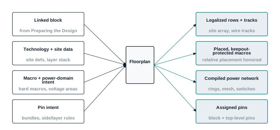
Before you open icc2_shell
- You have a target core utilization or a fixed die size from design planning, not a guess.Evidence: a one-line utilization or dimension target, with its source named.
- You know which hard macros exist and have at least a rough placement intent for each one.Evidence: a macro table with names, sizes, and either fixed coordinates or a relative-placement rule.
- You know which power domains are switched, and which strategy each one should compile against.Evidence: confirmation from the power architecture owner, matching the UPF committed in the previous chapter.
- You have a pin intent table for this block's sides, layers, and spacing, even in draft form.Evidence: a pin table from the interface owner, or your own draft awaiting review.
Building the shape, one dependency at a time
1. Flow boundary and the floorplan database model
Everything in this chapter operates on the same block object the previous chapter linked and saved — floorplanning does not create a new design, it adds physical geometry to an existing one. Before this chapter, the block has no die, no core, no rows, no tracks: every coordinate-based command in this chapter would either error or silently operate on an undefined space. The first real action in this chapter, initialize_floorplan, is what gives the block a coordinate system at all.
Once a floorplan exists, ICC2 tracks it as a set of distinct, related objects: a die boundary, a core boundary, a site array (rows), and independently-managed routing tracks per layer. Commands that change one of these do not automatically change the others — resizing the die does not resize the core unless you ask it to, and neither resizes the routing tracks, which is why modify_die_area and create_track/derive_tracks stay separate concerns throughout this chapter.
2. Channeled, abutted, and narrow-channel floorplans
ICC2 supports three named floorplan styles for hierarchical designs with multiple blocks. A channeled floorplan leaves open space between blocks so the tool can place top-level standard cells and route freely in the gap. An abutted floorplan pushes blocks directly against one another, leaving no room for top-level cells; this avoids wasted area but usually requires over-the-block routing and much more careful clock and feedthrough planning. A narrow-channel floorplan is a deliberate middle ground: some block edges abut, while a narrow channel is reserved only where a specific purpose — typically top-level clock routing — actually needs one.
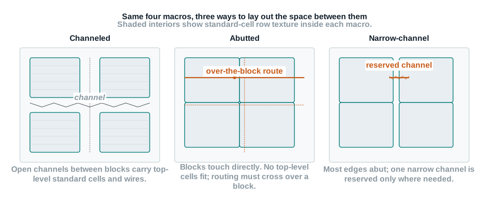
3. Creating the initial floorplan
initialize_floorplan is the command that gives a linked block its first die boundary, core boundary, site array, and wire tracks in one step. It accepts a -control_type of either core (the default) or die: with core, you specify the core's dimensions and the tool adds the core offset outward to compute the die; with die, you specify the die's dimensions and the tool subtracts the core offset inward to compute the core. Either the exact side lengths (-side_length) or a target utilization (-core_utilization) can drive the sizing, and non-rectangular shapes — L, T, and U — are supported through -shape for designs that need them.
For Nimbus‑8, the core dimension is already fixed by the project's floorplan target at 3.20 mm × 3.20 mm, so this chapter uses -control_type core with an explicit -side_length and a modest -core_offset for the die-to-core margin, rather than deriving the die from a utilization target. Utilization arithmetic, below, shows how utilization is used here in reverse — as a validation check on the achieved density, not as the input that sized the die.
4. Rows, site arrays, and routing tracks
initialize_floorplan creates a default site array and a first set of tracks, but real designs routinely need to redefine tracks explicitly — for a nondefault routing rule, a specific pitch, or a layer the default pass did not cover correctly. create_track creates tracks on a named layer with an explicit pitch (-space), track count, and starting offset; remove_tracks clears existing tracks before a clean re-creation; report_tracks reports the direction, start point, count, and pitch of every track set in the design, which is the only reliable way to confirm a track command did what you intended rather than what you typed.
Where track constraints have already been defined (through set_track_constraint, out of this chapter's scope but worth knowing by name), derive_tracks generates tracks automatically from those constraints across one or more layers, which is less error-prone than hand-specifying pitch and offset per layer once a project has standardized its track rules.

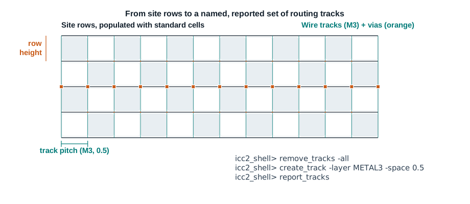
create_track -space or the derived constraint says. Neither is arbitrary, and report_tracks is how you confirm the pitch you see here is the pitch actually in the database.5. Adjusting die size, aspect ratio, and utilization target
A floorplan is rarely right on the first attempt. modify_die_area resizes the core or die of an existing floorplan without starting over: by an explicit scaling factor on area, height, or width; by a target -core_utilization, which the tool uses to compute how much resizing is needed; or by -sizing_type, which fixes one dimension (width, height, or aspect ratio) while the tool solves for the other. -fixed_edges lets you pin specific sides so a resize grows only in the direction you intend, which matters when a macro or pin is already placed against an edge you do not want to move.
6. Utilization arithmetic: from cell area to achieved density
Utilization is not a setting you choose once and trust — it is a measured ratio the tool computes from real geometry with report_utilization: the standard-cell and macro area actually present, divided by the core area actually defined. For Nimbus‑8, working from this guide's fixed teaching numbers (9.90 million standard cells, 72 SRAM macros, one DDR PHY macro, on a 3.20 mm × 3.20 mm = 10.24 mm² core), the worked example below computes an achieved utilization of roughly 82%, with macro area alone accounting for about 24% of the core.
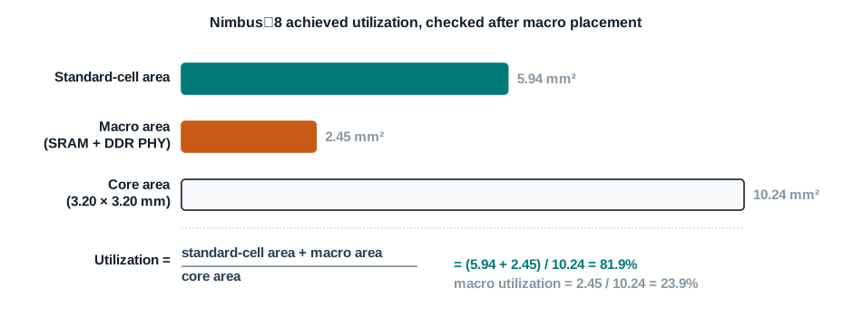
This is also where a target utilization set earlier (as a -core_utilization argument to initialize_floorplan or modify_die_area) gets checked against reality: those commands use the target to size or resize the die before anything is placed; report_utilization tells you what actually landed once macros and standard cells occupy real space.
7. Setting macro constraints and keepouts
Hard macros carry their own constraint surface, separate from ordinary placement blockages: a macro can be given an orientation, a legal placement region, and a keepout margin using the same create_keepout_margin command introduced in Preparing the Design. In a floorplan context, that margin is almost always what keeps the placer from butting a standard cell directly against a macro's pin edge, which is one of the most common sources of legalization failures once real placement begins.
8. Relative macro placement
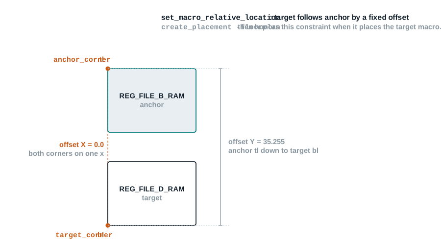
set_macro_relative_location is the command that makes macro placement reviewable instead of anecdotal: it fixes a target macro's position as a named offset from a named anchor object's corner, rather than an absolute coordinate a second engineer has no way to sanity-check without re-deriving it. The target can be a hard macro or a macro array; the anchor can be another hard macro, a block, an I/O pad, a voltage area, or the core area itself if no anchor is given. report_macro_relative_location confirms the constraint is recorded exactly as intended before anything is placed against it.
9. Running floorplan-stage placement
Defining relative-placement constraints does not, by itself, place anything — create_placement -floorplan is the command that actually executes macro placement, honoring every set_macro_relative_location constraint in force and applying floorplan-tuned effort and congestion controls distinct from ordinary coarse placement. This is also the point where application options such as plan.macro.style (on-edge, freeform, or an automatic mix) and plan.place.auto_create_blockages (automatic thin-channel blockage creation between macros) start to matter, though this chapter treats their defaults as adequate for Nimbus‑8 and flags them by name for later tuning rather than covering every option in depth.
10. Reserving space with placement blockages
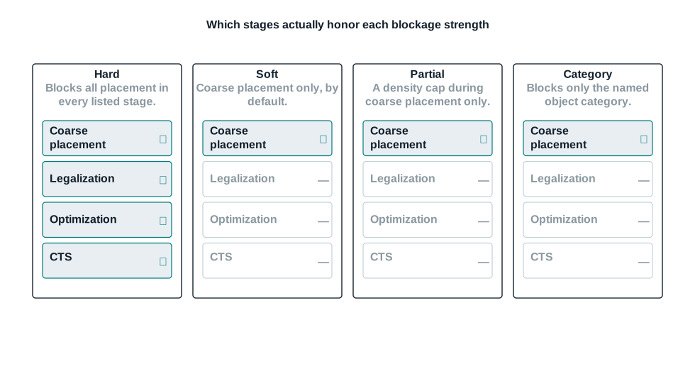
Placement blockages, introduced for physical constraints in the previous chapter, do real work at the floorplan stage: reserving a region for a future macro that has not been placed yet, protecting a thin channel between two hard macros from being silently filled with standard cells, or capping density near a pad ring margin with a partial blockage instead of forbidding placement outright. The strength you choose determines which later stages honor it — a distinction that matters more here than anywhere else in the flow, because a floorplan-stage blockage chosen at the wrong strength quietly stops protecting its region the moment legalization or optimization runs.
11. Power planning interfaces: domains, PG nets, and routing mode
Floorplan is where the power intent committed in the previous chapter becomes physical. connect_pg_net, already introduced for logical PG connectivity, is the same command used here as the entry point into physical power planning — without real connectivity in place, there is nothing for a compiled power network to attach to. From there, the design's PG routing mode (which strategy patterns are legal, and on which layers) is set up through the power planning strategy commands this chapter treats as configuration, deferring their full option surface to the reference documentation, and used directly by compile_pg in the next concept.
12. Building the power network: rings, mesh, and rails
compile_pg is the single command that builds the actual power and ground network — straps, rings, macro connections, standard-cell connections, and vias — from one or more named power planning strategies you have defined in advance. It supports an -ignore_drc escape hatch for exploratory passes, a -show_phantom preview mode, and an -undo option for backing out a strategy that did not work, but the default, careful path is: define a strategy, compile it, and check the result before moving on.

13. Inserting power switches for switched domains
A switched power domain needs an actual switch cell between its unswitched input supply and the switched rail its cells connect to — create_power_switch defines that cell: its domain, its input and output supply ports, its control port (the signal that turns it on and off), and optionally an acknowledge port, on/off states, and resistance characteristics for the cells it represents. This is a UPF-adjacent, power-architecture-defined object, not a purely physical one — the switch's electrical behavior comes from the power intent, and floorplanning is where it becomes a real, placeable, physical cell.
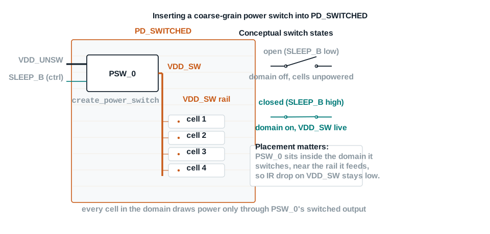
compile_pg and connectivity checks can verify.14. Block pin constraints and pin placement
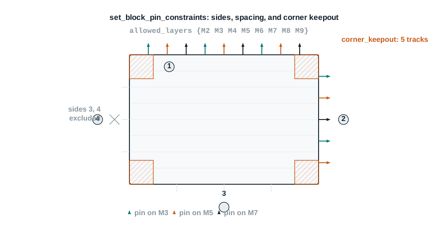
Block-level pin rules are set with set_block_pin_constraints: which layers pins may use, how much spacing separates adjacent pins, how much keepout distance protects a block's corners, and which sides are allowed or explicitly excluded. The reference documentation itself flags set_block_pin_constraints as scheduled for retirement in favor of create_block_pin_constraint in later releases — both exist in this release, and this chapter uses the still-current command while naming its replacement, exactly the kind of transition worth knowing about before it surprises you in a release upgrade. place_pins is the command that actually places pins — on specified cells, nets, pins, or ports — honoring every constraint set beforehand, with a -legalize option for adjusting existing pin placement into compliance rather than starting over.
15. Validating the floorplan before handoff
The floorplan exit gate rests on the same principle as the previous chapter's: prove it, do not assume it. report_utilization confirms achieved density against the target. Floorplan rule validation (density, spacing, enclosure, and area rules for advanced technology nodes, covered by name here since this guide's teaching node does not require deep coverage of them) catches geometry that violates a technology-specific constraint the layout view will not visually flag. Power network integrity checks — named here, detailed further in later chapters where routing makes them fully actionable — catch missing vias and connectivity gaps. Together with the reports in Reports and how to read them, these are what actually justify a handoff to Placement and Optimization.
The commands worth knowing cold
Every card below follows the same eight-point shape used throughout this guide, and every syntax line has been checked against the ICC2 Tcl command reference for this release. Where your installed release differs, trust man <command> over this page.
initialize_floorplan
Creates an initial floorplan: die, core, site array, and wire tracks, in one step.
- What it isCreates a die boundary, a core boundary, a default site array, and a first set of wire tracks, either coincident or offset from one another.
- Why you run itIt is the first command that gives a linked block a real coordinate system to place anything into.
- When in flowFirst in this chapter, immediately after the previous chapter's saved checkpoint is reopened.
- Exact Tcl
icc2_shell> initialize_floorplan -control_type core \ -side_length {3200 3200} -core_offset {40 40 40 40} - What ICC2 changesCreates the die and core boundaries, a default site array, and default wire tracks; with
-control_type core, the die is computed by adding the core offset outward. - What to read back — proof it took effectA floorplan report showing the die and core dimensions matching what you specified; the layout view showing a nonzero core area.
- Trap
-control_typechanges what your dimensions mean. The same-side_lengthvalue produces a smaller core under-control_type diethan under-control_type core, because the offset is subtracted instead of added. - If you skip itNo coordinate system exists; every later command in this chapter that references a location errors or has nothing to operate on.
create_track
Creates routing tracks for a named layer at an explicit pitch.
- What it isCreates a set of routing tracks on one layer, with an explicit pitch, count, starting offset, and direction.
- Why you run itThe default tracks
initialize_floorplancreates are not always what a specific layer or a nondefault rule requires. - When in flowRight after the initial floorplan exists, before macro placement.
- Exact Tcl
icc2_shell> remove_tracks -all
icc2_shell> create_track -layer METAL3 -space 0.5
icc2_shell> report_tracks
- What ICC2 changesRemoves any existing tracks on the target scope, then creates a new track set on the named layer at the given pitch, starting by default at half the pitch inside the die area.
- What to read back
report_tracksfor the direction, start point, count, and pitch actually created — not just that the command returned without error. - TrapRedefining tracks after macros are placed can shift the effective pitch relative to pins that were positioned against the old grid; sequence this before macro placement.
- If you skip itWhatever tracks
initialize_floorplandefaulted to remain in force, which is not always what the technology's routing rules for that layer actually intend.
derive_tracks
Generates tracks automatically from previously defined track constraints.
- What it isCreates a set of track objects for the current block that satisfy a previously defined track constraint, by layer and label.
- Why you run itOnce track rules are standardized as constraints, this is less error-prone than hand-specifying pitch and offset per layer with
create_track. - When in flowAlternative to
create_track, wherever track constraints already exist. - Exact Tcl
icc2_shell> derive_tracks -layers {M1 M2} -verbose - What ICC2 changesCreates tracks on the named layers that satisfy the default-label track constraint, or a named one if
-labelsis given. - What to read backThe
-verboseoutput during generation, plusreport_tracksafterward for the same confirmationcreate_trackneeds. - TrapWith no
-labels, the command searches only default-label constraints in the given layers; a project-specific labeled constraint set is silently skipped unless named explicitly. - If you skip itNothing breaks — this is a convenience over
create_track, not a required step, unless your project standardizes on labeled track constraints.
modify_die_area
Resizes an existing die or core area without starting the floorplan over.
- What it isShrinks or expands the die or core, by an explicit scaling factor, a target utilization, or a fixed sizing type, with specific edges optionally held fixed.
- Why you run itTo correct a floorplan that misses its utilization target, or to grow a die that congestion analysis shows is too tight, without discarding placed macros.
- When in flowAny time after
initialize_floorplan, most often after an early utilization check. - Exact Tcl
icc2_shell> modify_die_area -core_utilization 0.80 \ -sizing_type fixed_aspect_ratio - What ICC2 changesResizes the core (and, correspondingly, the die) to approach the target utilization, holding the aspect ratio fixed unless a different
-sizing_typeis given. - What to read back
report_utilizationafter the resize, compared against the target you set. - TrapLarge single resizes risk excessive utilization or macros that no longer fit; the reference documentation itself recommends small increments with a routability check after each one.
- If you skip itA floorplan that misses its target stays missed — there is no automatic correction elsewhere in the flow.
report_utilization
Reports the achieved utilization of the current block, measured from real geometry.
- What it isComputes and reports the fraction of a scoped area — by default the whole core — occupied by placed standard-cell and macro area.
- Why you run itIt is the only trustworthy way to know achieved density; a target utilization is a plan, not a measurement.
- When in flowAfter macro placement, and again after any later floorplan edit that changes occupied area.
- Exact Tcl
icc2_shell> report_utilization -verbose - What ICC2 changesNothing — this is a read-only report.
- What to read backThe reported utilization ratio itself, plus, with
-verbose, the breakdown that produced it. - TrapScoping with
-regionor-of_objectsreports utilization for a subset, not the whole core — easy to misread as a global figure if the scope is not checked. - If you skip itYou are trusting a target number you never actually measured, which is exactly the "looks fine" failure mode this guide keeps warning against.
set_macro_relative_location
Constrains a macro's placement as a named offset from an anchor object.
- What it isRecords a constraint fixing a target macro's specified corner at a given X/Y offset from an anchor object's specified corner.
- Why you run itIt makes macro placement traceable and reviewable, instead of a coordinate nobody can independently justify.
- When in flowAfter the floorplan exists, before running
create_placement -floorplan. - Exact Tcl
icc2_shell> set_macro_relative_location \ -target_object [get_cells I_REG_FILE_D_RAM] \ -target_orientation R0 -target_corner bl \ -anchor_object [get_cells I_REG_FILE_B_RAM] -anchor_corner tl \ -offset {0.0000 35.2550} -offset_type fixed - What ICC2 changesRecords the constraint; it does not move anything by itself.
- What to read back
report_macro_relative_locationfor a table confirming target, anchor, corners, and offset exactly as intended. - TrapWith no
-anchor_object, the constraint is relative to the parent design, not to nothing — a common misreading when a constraint appears to "not do anything" against another macro. - If you skip it
create_placement -floorplanis free to place the macro anywhere legal, which is rarely where a reviewer would expect it.
create_placement -floorplan
Runs floorplan-tuned coarse placement, honoring relative-placement constraints.
- What it isThe
-floorplanoption tocreate_placement, which performs macro placement using effort levels and controls tuned specifically for floorplanning, honoring every macro constraint already in force. - Why you run itDefining relative-placement constraints does not place anything by itself; this command executes them.
- When in flowAfter all macro constraints for this pass are defined.
- Exact Tcl
icc2_shell> create_placement -floorplan - What ICC2 changesPlaces hard macros (and, depending on application options, creates automatic thin-channel blockages) according to every macro constraint currently defined.
- What to read backThe layout view for a visual check, plus
report_macro_relative_locationre-confirmed against actual placed coordinates. - TrapThe application option
plan.place.auto_create_blockagescan create blockages you did not explicitly ask for, in thin channels between macros; review what actually got created, not just where macros landed. - If you skip itMacros stay unplaced, and nothing downstream — keepouts, the power network, pin assignment — has real macro geometry to plan against.
create_placement_blockage
Reserves a named region with a declared placement strength.
- What it isA rectangular or rectilinear region with a declared strength — hard, soft, partial, category, and related variants — limiting what may be placed inside it.
- Why you run itTo protect a thin channel between macros, reserve space for a future macro, or cap density near a sensitive region without forbidding placement outright.
- When in flowAfter the floorplan and macro placement exist, before standard-cell placement in the next chapter.
- Exact Tcl
icc2_shell> create_placement_blockage -boundary {{1550 200} {1650 3000}} \ -type hard -name ddrphy_channel_reserve - What ICC2 changesCreates the named blockage at the declared strength; each call creates exactly one strength of blockage.
- What to read back
get_placement_blockagesfor a collection of what actually exists; cross-check strength against the stage you meant to protect, using the blockage-strength gallery above. - TrapSoft, partial, category, and relative-placement blockages all bind coarse placement only by default — the single most common misreading of this command, repeated from the previous chapter because it matters even more here.
- If you skip itThe channel or region you meant to protect is open to whatever placement or legalization decides to put there.
compile_pg
Builds the power and ground network from one or more named strategies.
- What it isCreates straps, rings, macro connections, standard-cell connections, and vias, based on the power planning strategies named in
-strategies. - Why you run itIt is the command that turns a power planning strategy definition into an actual, physical power network.
- When in flowAfter macros are placed and PG connectivity exists, before pin assignment.
- Exact Tcl
icc2_shell> compile_pg -strategies {core_ring core_mesh std_cell_rail} - What ICC2 changesBuilds the physical PG network geometry for every named strategy, in the order strategies were defined unless a via rule between strategies says otherwise.
- What to read backA power network integrity report for missing vias and connectivity, plus a visual check of ring, mesh, and rail coverage in the layout view.
- Trap
-ignore_drcis meant for exploratory passes; a network compiled with DRC ignored and never re-compiled cleanly is not a signoff-ready network no matter how complete it looks. - If you skip itThere is a floorplan and placed macros, but no real power delivery network for anything placed inside the core to connect to.
create_power_switch
Defines a power switch cell for a switched power domain.
- What it isDefines a switch's domain, its input and output supply ports, its control port, and optionally its acknowledge port, on/off states, and resistance characteristics.
- Why you run itA switched domain has no way to actually turn off without a real switch cell tying its rail to an unswitched supply through a controlled path.
- When in flowAfter power intent is committed and the domain's physical region exists, before or alongside
compile_pgfor that domain. - Exact Tcl
icc2_shell> create_power_switch PSW_0 -domain PD_SWITCHED \ -input_supply_port {VDD_UNSW VDD} \ -output_supply_port {VDD_SW VDD_SW_NET} \ -control_port {SLEEP_B sleep_b_net} - What ICC2 changesDefines the switch object with its supply and control associations; a physical switch cell is instantiated and connected through the power planning flow that follows.
- What to read backA power switch report confirming the domain, ports, and control association match what the power architecture owner specified.
- TrapGetting the control polarity wrong (active-high versus active-low, matching the
_Bnaming convention or its absence) produces a domain that is on when it should be off, a mistake that does not show up until functional or power-aware simulation. - If you skip itA domain marked switched in UPF has no physical way to switch; downstream checks will flag the gap, later and more expensively than here.
set_block_pin_constraints
Sets side, layer, and spacing rules for a block's pins.
- What it isRestricts which metal layers, sides, spacing, and corner keepout apply to a block's or the top design's pins.
- Why you run itTo make pin placement defensible against an interface specification, rather than wherever the placer finds room.
- When in flowBefore
place_pins, once macro placement and the power network are stable enough that pin sides make sense. - Exact Tcl
icc2_shell> set_block_pin_constraints -allowed_layers {M2 M3 M4 M5 M6 M7 M8 M9} \ -pin_spacing 5 -corner_keepout_num_tracks 5 - What ICC2 changesRecords the constraint set for subsequent pin placement to honor.
- What to read back
report_block_pin_constraintsfor the effective layer, spacing, and keepout values. - TrapThis command is flagged for retirement in favor of
create_block_pin_constraintin later releases — both exist in this release, but confirm which one your installed release actually expects before scripting around it long-term. - If you skip it
place_pinsfalls back to whatever technology defaults apply, which rarely matches a specific interface specification.
place_pins
Places pins on the current block or design, honoring existing pin constraints.
- What it isPlaces pins for specified cells, nets, pins, or ports, honoring any block, individual, or bundle pin constraints already defined.
- Why you run itIt is the command that actually turns pin intent into real physical pin locations.
- When in flowAfter block and any individual pin constraints are set, near the end of this chapter's flow.
- Exact Tcl
icc2_shell> place_pins -self - What ICC2 changesPlaces pins consistent with every constraint currently defined;
-legalizeinstead adjusts existing pin placement into compliance without a full re-placement. - What to read backThe layout view for side and spacing sanity, plus a pin report confirming placed count matches the interface specification's pin count.
- TrapIndividual net or pin constraints that conflict with bundle constraints cause the bundle constraint to be dropped for that net, silently, rather than raising an error — check for this explicitly when a bundle looks incompletely honored.
- If you skip itNo pins exist at real physical locations, and nothing at integration or in top-level routing has a defined attachment point.
Nimbus‑8: floorplanning a teaching design end to end
Continuing from the previous chapter's saved checkpoint: 9.90 million standard cells, 72 SRAM macros, one DDR PHY hard macro, a 3.20 mm × 3.20 mm core target, and four clocks. This chapter works the single-voltage path for Nimbus‑8 itself; the switched-domain power-switch flow is exercised on Lyra‑2 in the mini lab below, reusing the PD_SWITCHED domain already established for it.
Step 1 — reopen the checkpoint
icc2_shell> open_lib ../libs/nimbus8_lib
icc2_shell> current_block
{nimbus8_top}
Proof: current_block returns the same block the previous chapter saved, confirming this chapter is building on validated state, not a fresh unlinked design.
Step 2 — initial floorplan
icc2_shell> initialize_floorplan -control_type core \
   -side_length {3200 3200} -core_offset {40 40 40 40}
/* core fixed at 3.20mm x 3.20mm per teaching target; 40um core_offset on every side */
Proof: a floorplan report shows a 3200 × 3200 (micron) core and a 3280 × 3280 die, and the layout view shows a nonzero core area for the first time in this guide.
Step 3 — rows and tracks
icc2_shell> remove_tracks -all
icc2_shell> create_track -layer METAL3 -space 0.5
icc2_shell> report_tracks
Layer          Direction     Start         Tracks    Pitch          Attr
------------------------------------------------------------------------
METAL3             Y         0.250          6398     0.500       default
Proof: the reported pitch and direction match what was requested; the track count is consistent with a 3.20 mm core at a 0.5 µm pitch, not a stale default from initialization.
Step 4 — macro constraints and relative placement
icc2_shell> create_keepout_margin -outer {10 10 10 10} nimbus8_ddrphy
icc2_shell> set_macro_relative_location \
   -target_object [get_cells nimbus8_sram_01] -target_orientation R0 -target_corner bl \
   -anchor_object [get_cells nimbus8_ddrphy] -anchor_corner tl \
   -offset {0.0000 20.0000} -offset_type fixed
icc2_shell> report_macro_relative_location
Proof: report_macro_relative_location lists the constraint with the exact target, anchor, corners, and offset intended — before anything has actually moved.
Step 5 — run floorplan placement
icc2_shell> create_placement -floorplan
Proof: the layout view shows the DDR PHY macro and its relatively-placed SRAM neighbor at the intended offset; report_macro_relative_location re-run against actual placed coordinates confirms the constraint was honored, not just recorded.
Step 6 — reserve the routing channel and check utilization
icc2_shell> create_placement_blockage -boundary {{1550 200} {1650 3000}} \
   -type hard -name ddrphy_channel_reserve
icc2_shell> report_utilization -verbose
Utilization: 81.9%
Proof: the reported utilization matches the arithmetic worked out in Utilization arithmetic — roughly 82%, not an assumed or carried-forward target number.
Step 7 — power network
icc2_shell> connect_pg_net -automatic
icc2_shell> compile_pg -strategies {core_ring core_mesh std_cell_rail}
/* single-voltage: one strategy set covers the whole core */
Proof: a power network integrity report shows zero missing vias, and the layout view shows a ring at the core perimeter, a mesh crossing the interior, and rails at every standard-cell row.
Step 8 — pin assignment
icc2_shell> set_block_pin_constraints -allowed_layers {M2 M3 M4 M5 M6 M7 M8 M9} \
   -pin_spacing 5 -corner_keepout_num_tracks 5
icc2_shell> place_pins -self
Proof: a pin report shows every top-level port placed, on an allowed layer, with the specified spacing and corner keepout honored.
Step 9 — checkpoint
icc2_shell> save_lib nimbus8_lib
Saving library 'nimbus8_lib'
1
Checkpoint / rollback point: this is the floorplan Placement and Optimization will build on. Treat the return value 1 as confirmation, the same discipline carried from the previous chapter.
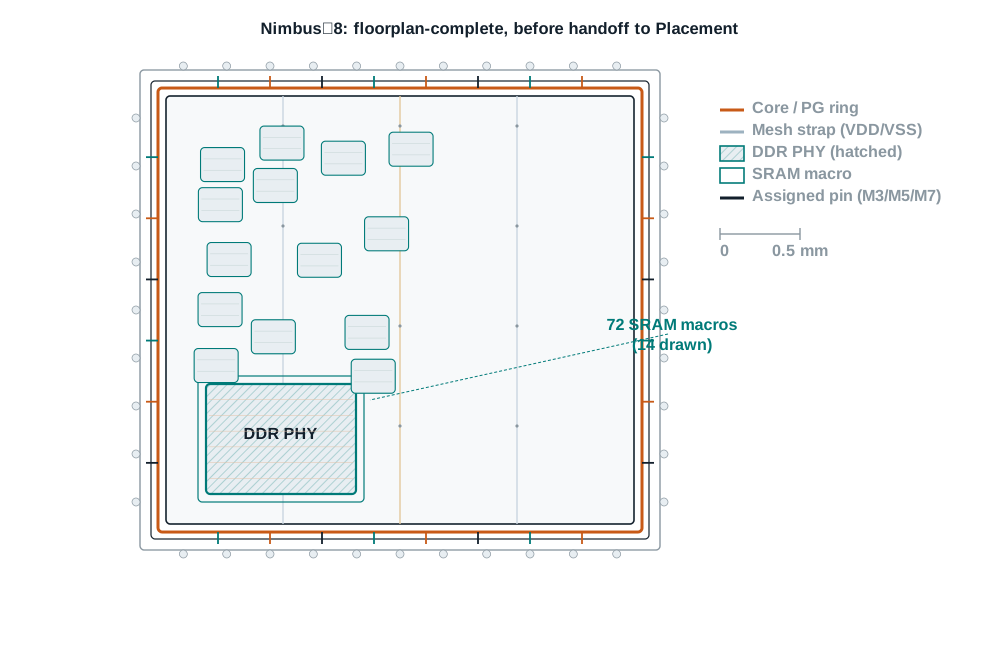
What to look for in the GUI
As in the previous chapter, no screenshots are supplied — the habit of looking with intent outlasts any static picture. After each step above, open the layout view and check:
- After
initialize_floorplan: does the core outline match the 3.20 mm × 3.20 mm teaching dimension, with a visibly distinct die boundary offset outward by the core offset? - After track creation: zoom in far enough to see individual track lines, and confirm the pitch visually matches the numeric value reported — a pitch off by a factor of ten is a common, easy-to-miss unit mistake.
- After macro placement: does the SRAM macro placed relative to the DDR PHY actually sit at the offset you specified, not just "somewhere nearby"?
- After
compile_pg: toggle power/ground layers on their own, separate from routing layers, and confirm ring, mesh, and rail all appear as distinct, connected tiers, not a single undifferentiated mass. - After
place_pins: confirm pins landed on the sides and layers you specified, and that no pin sits inside a keepout margin or placement blockage you defined earlier.
Reading proof, not just running commands
| Report | What it proves | Red flag to look for |
|---|---|---|
report_tracks | Track direction, start point, count, and pitch match intent, per layer | A pitch or start point that does not match what you specified, or a layer missing entirely |
report_macro_relative_location | Every macro relative-placement constraint is recorded and honored, target and anchor both | A macro whose reported placement does not match its constrained offset after create_placement -floorplan |
get_placement_blockages | Every blockage exists at the strength and boundary intended | A blockage with the wrong strength for the stage you meant to protect |
report_utilization -verbose | Achieved core utilization, measured from real geometry, not assumed from a target | An achieved figure far from the target with no explanation on record |
Power network integrity report (post-compile_pg) | No missing vias, no unresolved connectivity gaps in the compiled network | Any nonzero missing-via or connectivity-gap count left unexplained |
| Power switch report | Every switched domain has a real switch cell with correct supply and control associations | A domain marked switched in UPF with no corresponding switch object |
report_block_pin_constraints | Layer, spacing, and corner-keepout pin rules match the interface specification | An allowed-layers list wider or narrower than the specification intends |
Pin placement report (post-place_pins) | Every expected pin is placed, on an allowed side and layer | A missing pin, or a pin placed on an excluded side |
When something is wrong, start here
| Symptom | Likely cause | Where to look first |
|---|---|---|
| Core dimensions are not what you specified | Confusion between -control_type core and -control_type die in initialize_floorplan | The floorplan report's die vs. core dimensions, compared against your intended control type |
| Track pitch looks wrong by a large factor | A units mismatch, or a stale track set that was never actually removed before re-creation | report_tracks output, and whether remove_tracks ran first |
| A macro is not where its relative-placement constraint says it should be | create_placement -floorplan was never re-run after the constraint was added or changed | Command order in your script; re-run and re-check |
| Standard cells land in a region you meant to protect | A soft, partial, or category blockage was used where a hard blockage was needed | Blockage strength table in Reserving space with placement blockages |
| Achieved utilization is far from target | The target was set before macro placement changed the occupied area, and never re-checked | report_utilization -verbose, run again after every placement change |
compile_pg completes but a region shows no rail coverage | A strategy's -region or extension setting did not actually cover that area | The power planning strategy definitions used in -strategies |
| A switched domain never actually powers down in simulation | Power switch control polarity is inverted relative to the intended control signal | create_power_switch's -control_port definition and the UPF supply-state logic |
| A pin lands on a side you explicitly excluded | An individual pin or bundle constraint overrode the block-level side exclusion | Precedence between individual, bundle, and block pin constraints |
The Floorplan exit gate
This is the same checklist a careful design planning reviewer would use before approving a handoff to Placement and Optimization. Every item names its evidence; "looks fine" is not evidence.
- Die and core boundaries match the intended dimensions and control type.Evidence: a floorplan report compared line by line against the design planning target.
- Rows and tracks are legal on every layer that matters, with no stale or default track sets left unreviewed.Evidence:
report_tracksoutput for every layer touched. - Every hard macro is placed with a traceable constraint, not a manual coordinate.Evidence:
report_macro_relative_locationmatching the macro placement table. - Every macro carries a real keepout margin at the correct strength.Evidence: keepout report or
get_attributecheck on every macro. - Placement blockages are named, scoped, and set to the strength that actually protects the stage intended.Evidence:
get_placement_blockagesreviewed strength by strength. - Achieved utilization is measured, documented, and reconciled with the target.Evidence:
report_utilization -verboseoutput kept with the checkpoint. - The power network is compiled with no missing vias or unresolved connectivity gaps.Evidence: power network integrity report reviewed line by line.
- Every switched domain has a real, correctly associated power switch.Evidence: power switch report matching the power architecture owner's domain list.
- Block pin constraints match the interface specification, and every pin is placed accordingly.Evidence:
report_block_pin_constraintsand the post-placement pin report, both checked. - Floorplan rules for the target technology node are validated, or findings are tracked.Evidence: floorplan rule validation output, or an issue register entry for anything outstanding.
- Saved checkpoint, logs, reports, and manifest are reproducible.Evidence: a second engineer can
open_libyour saved checkpoint and reproduce the same reports.
Lab: inserting a power switch into Lyra‑2's PD_SWITCHED domain
Lyra‑2, the small multivoltage teaching design from the previous chapter's mini lab, already carries two power domains — PD_ALWAYS_ON and PD_SWITCHED — and a DEF with a floorplan already defined, including a region reserved for PD_SWITCHED. This lab picks up exactly there: PD_SWITCHED has a physical home, but nothing yet actually switches it. All numbers remain synthetic teaching data.
Setup
- Lyra‑2's design library, with its committed UPF (
lyra2.upf) and the DEF-derived floorplan reopened from the previous chapter's checkpoint. - Confirmation from the power architecture owner of the intended control signal name and polarity for PD_SWITCHED.
Tasks
- Reopen the Lyra‑2 checkpoint and confirm the PD_SWITCHED voltage area still resolves correctly with
report_voltage_areas -verbose. - Define a power switch with
create_power_switchfor PD_SWITCHED, with an unswitched input supply, a switched output supply, and a control port matching the owner's specification. - Compile the power network for both domains with
compile_pg, using a strategy set that covers PD_ALWAYS_ON and PD_SWITCHED separately. - Run a power network integrity check and resolve or document every finding.
- Save the checkpoint and write a one-paragraph handoff note, as if for a reviewer who has not seen this lab, stating the control polarity you used and why.
Expected observations
The switched rail inside PD_SWITCHED should show no power connectivity until the switch's control port is driven active; if your first compile_pg pass reports a connectivity gap on the switched rail, check whether the switch was defined before or after connect_pg_net ran for that domain — sequencing this incorrectly is a common first-attempt mistake, not a tool defect.
Cleanup
Close the library with close_lib once you have confirmed the saved checkpoint reopens cleanly with open_lib in a fresh session, the same discipline as the previous chapter's lab.
25 questions worth being able to answer cold
Q1. What is the difference between the die boundary and the core boundary?
The die is the chip's outer physical edge; the core is the inner region that holds standard cells and macros, typically inset from the die by a core offset.
- What is happening
- The die-to-core margin often reserves space for I/O pads or a pad ring, which is not part of the placeable core area.
- The trap
- Treating "floorplan size" as one number instead of two distinct, related boundaries.
- What is being tested
- Whether the die/core distinction is automatic before relying on it in a command's
-control_typeoption.
Q2. What does -control_type core versus -control_type die change about initialize_floorplan?
- What is happening
- With
core, your dimensions apply to the core and the offset is added outward to compute the die. Withdie, your dimensions apply to the die and the offset is subtracted inward to compute the core. - The trap
- Assuming the same numeric
-side_lengthvalue produces the same core size under either control type. - What is being tested
- Reading an option's default and effect precisely, instead of assuming from the option's name alone.
Q3. What is the difference between a row and a routing track?
- What is happening
- A row is part of the site array — the grid standard cells snap to. A track is a per-layer routing grid that wires snap to. They are independent grids, not the same thing at different scales.
- The trap
- Using "grid" loosely enough that rows and tracks get conflated in a design review.
- What is being tested
- Precision about which grid a given legality problem actually belongs to.
Q4. Name the three floorplan styles and the one-sentence tradeoff each one makes.
- What is happening
- Channeled: open space between blocks for top-level cells and routing, at the cost of area. Abutted: no wasted area, at the cost of over-the-block routing and harder clock/feedthrough planning. Narrow-channel: a deliberate middle ground, reserving a channel only where a specific purpose needs one.
- The trap
- Treating "abutted" as always better because it wastes less area, ignoring its routing and clock-planning cost.
- What is being tested
- Whether the reader can state a real tradeoff, not just a definition.
Q5. What does set_macro_relative_location actually record, and what does it not do by itself?
- What is happening
- It records a constraint: a target macro's corner at a fixed offset from an anchor object's corner. It does not move anything —
create_placement -floorplanis what executes the placement. - The trap
- Assuming the macro has moved immediately after the constraint command returns.
- What is being tested
- The general habit, repeated throughout this guide, of separating "constraint defined" from "constraint executed."
Q6. Why does a hard macro almost always need a keepout margin?
- What is happening
- Without one, the placer can butt a standard cell directly against a macro's pin edge, which is a common source of legalization failures once real placement begins.
- The trap
- Treating the keepout margin as cosmetic spacing rather than a legalization safeguard.
- What is being tested
- Connecting a physical constraint to the concrete failure it prevents.
Q7. What does report_utilization actually measure?
- What is happening
- The fraction of a scoped area, by default the whole core, occupied by real, placed standard-cell and macro geometry — not an estimate and not the target you set earlier.
- The trap
- Quoting a target utilization as if it were a measured, achieved one.
- What is being tested
- The distinction between a plan and a measurement, applied to the one number floorplan reviews ask for most often.
Q8. What does a power switch's control port actually do?
- What is happening
- It is the signal that turns the switch, and therefore the switched domain's power, on and off.
- The trap
- Assuming a switch is inherently "on" by default with no attention to its control polarity.
- What is being tested
- Basic fluency with what a power switch definition actually specifies.
Q9. You defined a hard blockage to protect a routing channel, but standard cells still landed there during optimization two chapters from now. What is the most likely explanation?
- What is happening
- If the blockage was actually created with a different strength — soft, partial, or category — it stops protecting the region after coarse placement, by default.
- The trap
- Assuming a blockage's visual presence in the layout view proves its strength, rather than checking the report.
- What is being tested
- Whether "it shows up in the layout view" is treated as proof, which it is not.
Q10. Why might redefining routing tracks after macro placement cause a problem that did not exist before?
- What is happening
- Macro pins may already be positioned against the old track grid; redefining tracks can shift the effective pitch relative to those fixed pin locations.
- The trap
- Treating track redefinition as a purely cosmetic, low-risk change late in the flow.
- What is being tested
- Understanding why command order matters, not just command correctness in isolation.
Q11. A colleague scales the die down 20% in one modify_die_area call to hit a utilization target. What is the risk?
- What is happening
- A large single resize risks excessive utilization or macros that no longer physically fit; the reference documentation itself recommends small increments with a routability check after each one.
- The trap
- Treating utilization arithmetic as the only success criterion and ignoring routability and macro fit.
- What is being tested
- Whether the reader applies the "small increments, re-check each time" discipline under a real scenario.
Q12. What is the difference in behavior between create_track and derive_tracks?
- What is happening
create_trackcreates tracks directly from explicit pitch, count, and offset arguments.derive_tracksgenerates tracks automatically from previously defined track constraints, searching default-label constraints unless a label is specified.- The trap
- Running
derive_tracksexpecting it to work without any track constraints having been defined first. - What is being tested
- Whether a "convenience" command's actual dependency is understood, not just its name.
Q13. Why does this chapter treat set_block_pin_constraints and create_block_pin_constraint as both worth knowing?
- What is happening
- The reference documentation flags
set_block_pin_constraintsas scheduled for retirement in favor ofcreate_block_pin_constraint; both exist in the current release. - The trap
- Scripting long-term automation around a command flagged for retirement without checking its replacement.
- What is being tested
- Reading a deprecation notice as an action item, not a footnote.
Q14. What happens when an individual net's pin constraint conflicts with a bundle constraint covering that net?
- What is happening
- For side, offset, or layer conflicts,
place_pinsignores the bundle constraint for that net and places the other bundle pins together regardless; for width, length, or spacing conflicts, both individual and bundle constraints are honored together. - The trap
- Assuming any conflict simply errors out, rather than checking which category of conflict actually applies.
- What is being tested
- Precision about precedence rules that do not fail loudly when they apply.
Q15. Why is a power switch's association part of the physical floorplan flow, even though its behavior comes from UPF?
- What is happening
- UPF defines the power architecture's intent that a domain is switched;
create_power_switchand the floorplanning flow around it turn that intent into a real, placeable, physically connected cell. - The trap
- Treating power switch insertion as purely a UPF or purely a physical concern, when it is genuinely both.
- What is being tested
- Whether the reader can trace one concept across the logical/physical boundary this guide keeps returning to.
Q16. Why does this chapter check achieved utilization with report_utilization rather than trusting the -core_utilization value passed to initialize_floorplan?
- What is happening
- The target value sizes the die before anything is placed; only measurement after macro and standard-cell placement reflects what actually landed.
- The trap
- Reporting the input target in a design review as if it were the output measurement.
- What is being tested
- The plan-versus-measurement discipline applied specifically to utilization.
Q17. A reviewer asks you to prove a specific macro's placement is actually constrained, not just visually correct today. What do you show them?
- What is happening
report_macro_relative_locationfor the recorded constraint, plus the macro's actual current coordinates, to show the two agree — a snapshot alone proves nothing about whether the placement is protected against a future re-run.- The trap
- Pointing at the layout view as if today's visual state were the same as a durable, recorded constraint.
- What is being tested
- The same proof-over-opinion discipline from the previous chapter, applied to geometry instead of text reports.
- Verified Tcl snippet
icc2_shell> report_macro_relative_location
Q18. Your die comes out of initialize_floorplan noticeably larger than expected. Walk through your triage.
- What is happening
- Check
-control_typefirst — a die-controlled sizing subtracts the offset while a core-controlled sizing adds it, which alone can explain an unexpected size before assuming a units or macro-fit problem. - The trap
- Jumping straight to re-scaling with
modify_die_areabefore confirming the original command's option choice was correct. - What is being tested
- Checking the simplest, most likely explanation before reaching for a corrective command.
Q19. Two macros that should be adjacent per the placement table are separated by an unexpected gap after create_placement -floorplan. What do you check first?
- What is happening
- Whether
plan.place.auto_create_blockagesinserted an automatic thin-channel blockage between them, which is legitimate congestion-reduction behavior but easy to mistake for a placement bug. - The trap
- Assuming the relative-placement constraint itself is wrong before checking for an automatically inserted blockage.
- What is being tested
- Awareness of a specific automatic-behavior application option named in this chapter, not just the explicit constraint commands.
Q20. A power network integrity report shows missing vias only in one quadrant of the die. What do you investigate?
- What is happening
- Whether a power planning strategy's region or extension setting actually covers that quadrant, or whether a placement blockage or macro keepout there is blocking mesh or rail geometry from landing.
- The trap
- Re-running
compile_pgunchanged, hoping a transient issue resolves itself, instead of checking strategy coverage against the geometry actually present. - What is being tested
- Diagnosing a localized failure by checking what differs about that region, not re-running the same command blind.
Q21. A pin you explicitly excluded from side 3 with -exclude_sides still appears there after place_pins. What are the two most likely explanations?
- What is happening
- Either an individual pin or bundle constraint for that specific net overrides the block-level exclusion, or the exclusion was set after
place_pinshad already run once in the same session. - The trap
- Assuming the tool ignored the constraint outright, rather than checking constraint precedence and command order first.
- What is being tested
- The same command-order and object-scope diagnosis habit from the previous chapter's
dont_touchscenario, applied to pin constraints.
Q22. Your achieved utilization comes back at 91%, well above the 80% target, after macro placement. What do you fix, and in what order?
- What is happening
- Confirm the figure with
report_utilization -verboseto rule out a scoping mistake, then usemodify_die_areawith a target-core_utilizationto grow the core in small increments, re-checking routability and macro fit after each step, rather than one large resize. - The trap
- Jumping straight to a single large resize instead of the incremental, re-checked approach this chapter recommends.
- What is being tested
- Applying the die-scaling discipline from earlier in this chapter to a concrete, numeric scenario.
Q23. How would you decide between a channeled and a narrow-channel floorplan style for a design with three tightly-coupled blocks?
- What is happening
- The deciding factor is whether the design genuinely needs top-level cell placement and routing across most block boundaries (channeled) or only along specific paths, most commonly clock distribution, that justify a reserved channel while the rest of the boundary abuts (narrow-channel). Congestion analysis on a trial floorplan, not intuition, should confirm which paths actually need the reservation.
- The trap
- Defaulting to channeled everywhere out of caution, absorbing area cost the design does not actually need.
- What is being tested
- Judgment about matching floorplan style to a measured need, not a default habit.
Q24. A junior engineer asks why this chapter insists on relative macro placement instead of just dragging macros in the GUI to where they look right. How do you answer?
- What is happening
- A dragged placement has no recorded rationale a second engineer, or the same engineer six months later, can verify or reproduce; it also silently breaks the moment the design is re-floorplanned from an earlier checkpoint. A relative-placement constraint is both reviewable and durable across re-runs, at the cost of slightly more upfront ceremony.
- The trap
- Answering only "because it's more precise," without naming the reproducibility and review failure a dragged placement actually causes.
- What is being tested
- Whether the engineer can explain the underlying engineering-process reason, not just recite the recommended command.
Q25. How would you justify, to a skeptical lead, spending extra time on power switch polarity verification when functional simulation would eventually catch a mistake anyway?
- What is happening
- A polarity mistake caught in floorplan review costs a one-line constraint edit and a re-compile. The same mistake caught in functional or power-aware simulation costs a debug cycle across two additional flow stages before the root cause is even localized to floorplan. The cost asymmetry, not the certainty of eventually catching it, is the argument.
- The trap
- Arguing "it might not get caught otherwise," which is both weaker and less true than the actual cost-asymmetry argument.
- What is being tested
- Whether the engineer can make a cost-based case for early verification, the kind of argument that actually persuades a schedule-conscious lead.
Twelve facts worth having cold
initialize_floorplan control type-control_type core adds the offset outward to get the die; -control_type die subtracts it inward to get the core. Same numbers, different results.set_macro_relative_location vs. create_placement -floorplanmodify_die_area disciplinereport_utilizationcreate_power_switch scopeset_block_pin_constraints futurecreate_block_pin_constraint. Both exist now; confirm which your installed release expects for new scripts.Terms used in this chapter
- Abutted floorplan
- A floorplan style with no channel between blocks; blocks touch directly.
- Channeled floorplan
- A floorplan style with open space between blocks for top-level cells and routing.
- Checkpoint
- A saved, reopenable state of a design library on disk, written with
save_lib. - Core boundary
- The inner region of a floorplan holding standard cells and macros.
- Core offset
- The margin between the die boundary and the core boundary.
- Core utilization
- The fraction of core area occupied by standard-cell and macro area, either as a target or as a measured, achieved figure.
- Die boundary
- The outer physical edge of the chip.
- Keepout margin
- A region around a fixed object, inner or outer, where no other cell may be placed. Carried forward from Preparing the Design; used heavily around macros in this chapter.
- Narrow-channel floorplan
- A floorplan style mixing abutted edges with a channel reserved only where a specific purpose needs one.
- Placement blockage
- A named region with a declared strength limiting what may be placed inside it. Strength determines which stages honor it.
- Power ring
- A power and ground network tier running around the core perimeter.
- Power mesh
- A coarser power and ground network tier crossing the core's interior on upper metal layers.
- Power switch
- A cell inserted between an always-on supply and a switched domain's rail, controlled by a defined control port.
- Relative placement constraint
- A rule fixing one macro's position as an offset from a named anchor object's corner.
- Routing track
- A line on a routing layer, at a defined pitch, that wires on that layer are expected to align to.
- Site array / row
- The grid of legal standard-cell placement sites, laid out as horizontal rows.
- Standard-cell rail
- The finest tier of the power network, feeding individual standard-cell rows.
- Switched domain
- A power domain whose supply can be turned off by a power switch under control-signal direction.
Test yourself before moving on
- Explain, in one sentence each, what changes between
-control_type coreand-control_type dieoninitialize_floorplan. - A macro you constrained with
set_macro_relative_locationis not where you expect aftercreate_placement -floorplan. Name two things you would check before assuming the constraint is wrong. - Why does this chapter recommend defining routing tracks before running macro placement, not after?
- You need a region to stay clear of standard cells through legalization and CTS, not just coarse placement. Which blockage strength do you use, and why not soft or partial?
- Explain why
report_utilizationis described in this chapter as a measurement, and a target-core_utilizationvalue as a plan. - Name the three tiers of a compiled power network, and state which failure mode — not a routing error — a gap in any tier produces.
Answers
- With
core, your dimensions apply to the core and the offset is added outward to compute the die. Withdie, your dimensions apply to the die and the offset is subtracted inward to compute the core. - Whether
create_placement -floorplanwas actually re-run after the constraint was added, and whether the constraint's anchor and target corners were set as intended, viareport_macro_relative_location. - Because redefining tracks after macros are placed can shift the effective pitch relative to macro pins already positioned against the old grid.
- Hard. Soft, partial, and category blockages bind coarse placement only, by default, and stop protecting a region once legalization or optimization runs.
- The target value sizes the die before anything is placed; only
report_utilization, run after macro and standard-cell placement, reflects what actually occupies the core. - Ring, mesh, and rail. A gap at any tier shows up as IR drop, not as a routing error.
What to carry forward
| Topic | Fact worth carrying forward |
|---|---|
| Die and core | Two distinct, related boundaries; -control_type decides which one your dimensions actually describe. |
| Rows and tracks | Independent grids; define tracks before macro placement, and re-verify with report_tracks after any change. |
| Macro placement | A relative-placement constraint is recorded, not executed, until create_placement -floorplan runs. |
| Blockage strength | Only hard survives past coarse placement by default — the single most repeated trap in this guide. |
| Utilization | report_utilization measures; a target value only plans. Never carry the plan forward as if it were the measurement. |
| Power network | Ring, mesh, and rail are three tiers with three purposes; a gap in any one is an IR-drop risk, not a routing error. |
| Pin assignment | Individual and bundle constraints can silently override a block-level rule per net; check precedence, not just intent. |
Before you call this stage done
This is the same eleven-item exit gate from earlier in this chapter, repeated here as the final gate before handoff. See Stage completion checklist for the full evidence requirements attached to each item.
- Die and core boundaries match the intended dimensions and control type.
- Rows and tracks are legal on every layer that matters.
- Every hard macro is placed with a traceable constraint.
- Every macro carries a real keepout margin at the correct strength.
- Placement blockages are named, scoped, and set to the correct strength.
- Achieved utilization is measured, documented, and reconciled with target.
- The power network is compiled with no missing vias or unresolved gaps.
- Every switched domain has a real, correctly associated power switch.
- Block pin constraints match the interface specification, and pins are placed accordingly.
- Floorplan rules for the target technology node are validated, or findings are tracked.
- A saved checkpoint, with logs, reports, and manifest, reproduces cleanly for a second engineer.
Last word and bridge to Placement and Optimization
This chapter drew the shape everything else in this guide will be built inside of. That shape is now mostly fixed: the die will not casually resize again, hard macros will not casually move, and the power network's topology is set. What comes next fills that shape in. When placement congestion looks worse in one corner of the die than everywhere else, or a net refuses to route cleanly near a macro edge, the first productive move is almost always back here: is the keepout margin really what you think it is, is the blockage strength really what the stage in question honors, is the power mesh really covering that region.
The next chapter, Placement and Optimization, picks up exactly where this one leaves off: a legal, checkable floorplan with macros placed, power compiled, and pins assigned, but not a single standard cell placed yet. It covers coarse and detailed placement, timing- and power-driven optimization, and congestion — the discipline of filling in the shape this chapter defined without breaking anything this chapter proved.