Detailed Design Analysis
Placement and Optimization in ICC2: A Mentor Guide
How a legal, checkable floorplan gets a design's worth of standard cells placed, buffered, resized, and timing-closed through the place_opt flow — taught the way a senior engineer would explain it at the whiteboard.
What you will be able to do after this chapter
By the end of this chapter you will be able to take a legal, checkable Floorplan — die and core sized, macros placed, power compiled, pins assigned, but not one standard cell placed — and turn it into a fully placed, legalized, timing- and congestion-optimized design ready for clock tree synthesis, using the same command whether you run it as one step or five.
Concretely, you will be able to: run place_opt end to end and explain what each of its five internal stages actually does; run the same work as discrete steps with create_placement and legalize_placement when you need that control; steer placement with timing-driven, congestion-driven, and buffering-aware options instead of accepting whatever the default gives you; enable IR-drop-aware placement, concurrent clock and data optimization, and physical guidance from Design Compiler when a design calls for them; bank single-bit registers into multibit cells; pull a cluster of logic toward a fixed anchor with magnet placement; and prove every one of these worked with report_placement, report_utilization, and a placement status query — not with an impression of the layout view.
As with every chapter in this guide, the goal is not memorizing flags. It is building the same judgment a placement lead uses when deciding whether a design is actually ready for clock tree synthesis, so that when a CTS or routing problem shows up two stages later, you already know whether it traces back to a placement decision made here.
Why this stage matters in the full flow
Floorplan decided whether the design fits. Placement and Optimization decides whether it works — whether timing closes, whether the design is routable without heroics, whether power density stays sane, and whether area is spent efficiently. This is the stage where most of a project's timing and congestion story actually gets written, because it is the first point where every one of a design's millions of standard cells has a real, specific location and a real, specific set of neighbors.
It is also the stage most beginners underestimate, because place_opt looks like a single command. It is not one decision; it is five, each with its own job, each capable of being run alone when a specific problem calls for it. Treating it as "run place_opt and see what happens" is how a design ends up re-run three or four times with no clearer idea of what changed between attempts than at the start.
What enters, what must leave
| Enters this stage | Must leave this stage |
|---|---|
| A legal floorplan: die and core sized, rows and tracks defined, hard macros placed and keepout-protected | Every standard cell placed and legalized on the site grid, honoring every macro and blockage |
| A compiled power network and assigned pins from the previous chapter | A design optimized for timing, area, leakage power, and routability — not just placed |
| Committed timing constraints (from Preparing the Design) with no clock tree yet | A placement QoR report and utilization figure the tool computed, proving the optimization actually converged |
| Registers and clock-gating cells not yet merged, banked, or optimized as a group | Clock-gating cells merged, multibit banking applied where it helps, and a design ready for a temporary or real clock tree |
What does not leave this stage: a real clock tree (only a temporary, optional trial clock tree used internally, if enabled, and discarded before clock tree synthesis), or detailed routing. Those belong to Clock Tree Synthesis and Routing, in that order. This chapter's exit gate is a fully placed, timing-checked design a clock tree can be built on top of — not a routed one.
What you should already be comfortable with
- Everything from the Floorplan chapter (not included in this standalone package): a legal die and core, placed macros, a compiled power network, and assigned pins.
- Basic timing vocabulary: slack, setup and hold, and the idea that a "violation" is a number, not a feeling.
- What a buffer and an inverter do in a netlist, at least conceptually — this chapter buffers nets by the million without re-explaining what buffering is.
- Basic Tcl, as used throughout this guide: variables, lists, and running a command with options from
icc2_shell.
You do not need prior placement or optimization experience. Where this chapter uses a term for the first time, it defines it before relying on it.
By the end of this chapter, you will be able to…
- Explain
place_opt's five stages —initial_place,initial_drc,initial_opto,final_place,final_opto— and run any subset of them with-fromand-to. - Run standalone coarse placement and legalization with
create_placementandlegalize_placement, and say when that control is preferable to the combined command. - Turn on timing-driven, buffering-aware, and congestion-driven placement, and control the CPU effort spent on each.
- Merge clock-gating cells before placement and explain why sequencing that before
place_optchanges what the command does internally. - Enable IR-drop-aware placement and concurrent clock and data (CCD) optimization, and state what each one actually changes about the placed design.
- Bank single-bit registers into multibit cells with
identify_multibit, and split a bank back apart withsplit_multibitwhen it hurts more than it helps. - Use magnet placement to pull a cluster of logic toward a fixed anchor, and refine an existing placement's congestion with
refine_placement. - Prove a placement is actually done with
report_placement,report_utilization, and a placement-status query — not a glance at the layout view.
Think of it as moving the everyday furniture into a finished floor plan
Analogy. The previous chapter drew the floor plan and installed everything that cannot move — the built-in furniture (hard macros), the wiring (the power network), and the doors and windows (pins). This chapter moves in everything else: the desks, chairs, and shelves — the standard cells — and then walks through the apartment adjusting them room by room. First a fast, rough drop of every piece somewhere reasonable (initial_place). Then a walk-through making sure nothing blocks a doorway or a hallway (initial_drc: fixing up nets with too many branches, buffering long runs). Then a real arrangement pass for comfort and function (initial_opto: timing, area, congestion, leakage). Then small nudges so walking paths are clear (final_place: incremental re-placement plus legalization). Then a last, careful adjustment pass before guests arrive (final_opto).
Engineering translation. All five of those moves are what place_opt does in one command, in order, by default. "A fast rough drop" is coarse placement, also runnable alone with create_placement. "Making sure nothing blocks a doorway" is initial DRC fixing — high-fanout net synthesis and electrical DRC repair. "A real arrangement pass" is timing/area/congestion/leakage optimization. "Small nudges, then legalize" is incremental placement followed by legalize_placement—also runnable alone. "A last adjustment pass" is final optimization, where concurrent clock and data optimization and further legalization happen.
Terms this chapter depends on
| Term | Plain-English meaning |
|---|---|
| Coarse placement | A fast first pass that gives every standard cell an approximate, legal-ish location. |
| Legalization | The pass that moves cells onto real, non-overlapping site-grid positions without changing the netlist. |
place_opt stage | One of five named phases — initial_place, initial_drc, initial_opto, final_place, final_opto — that together make up the default placement and optimization flow. |
| Timing-driven placement | Placement that considers timing criticality when deciding where to put a cell, not just area and wire length. |
| Congestion-driven placement | Placement that spreads cells to avoid routing hot spots, at some cost to wire length or runtime. |
| IR-drop-aware placement | Placement that spreads cells with high voltage-drop values to reduce local power density. |
| Concurrent clock and data (CCD) optimization | Adjusting clock arrival times at registers (useful skew) together with datapath optimization, to trade positive slack where it helps. |
| Multibit register banking | Replacing several single-bit registers driven by the same clock with one equivalent multibit register cell. |
| Magnet placement | Pulling the standard cells connected to a fixed anchor object close to it, to shorten local wiring and reduce congestion. |
| Physical guidance (SPG) | Using a Design Compiler Graphical placement, carried over by DEF, as ICC2's placement starting point instead of starting from scratch. |
| Placement status | A per-cell state — unplaced, placed, fixed, legalize_only, or locked — controlling whether later commands are allowed to move it. |
| Bufferability | Whether a specific net segment can legally be buffered, given available supply nets, library cells, and any don't-touch or ideal-network settings. |
The place_opt pipeline

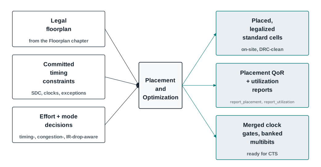
-from and -to let you enter or leave this pipeline at any of the five named points, not only at the ends.What comes in, what must go out
| Item | Owner | Format | Required? | Validation | Failure impact |
|---|---|---|---|---|---|
| Legal floorplan with placed macros | Floorplan (this engineer, previous chapter) | Design library checkpoint | Required | open_lib succeeds; report_utilization matches the checkpoint's recorded figure | Placing standard cells against an unvalidated floorplan re-surfaces geometry problems the previous chapter exists to catch |
| Committed timing constraints | Preparing the Design (two chapters back) | SDC, loaded into the block | Required | Timing-driven and congestion-driven placement options depend on real, not default, constraints | Placement without real timing constraints optimizes against nothing meaningful, producing a QoR report that looks fine and means little |
| Effort and mode decisions: timing-driven, congestion-driven, buffering-aware | This engineer, informed by an initial place_opt pass | Command-line options and application-option settings | Recommended, not strictly required | A first pass's report_placement and congestion map justify which options are worth the runtime cost | Guessing which options a design needs wastes runtime on the wrong lever |
| Multibit banking policy | Design methodology / this engineer | set_multibit_options settings, or none | Optional | report_multibit after banking, compared against expectations | Unplanned banking or debanking changes area and clock tree structure in ways CTS then has to absorb |
| Artifact | Consumer | Persistence | Handoff rule |
|---|---|---|---|
| Fully placed, legalized standard-cell placement | Clock Tree Synthesis | save_lib checkpoint | Never hand off a placement whose legalization was not re-confirmed after the last edit |
| Placement QoR and utilization reports | This engineer, design planning, CTS owner | Kept with the checkpoint | Report the achieved figures the tool computed; never carry a target forward as if it were measured |
| Merged clock-gating cells, banked multibit registers | Clock Tree Synthesis | Stored in the block | Document any manual banking or debanking decision made outside the default flow, with a reason |
| Placement status on any manually fixed or locked cells | Every later stage | Stored in the block | Document why a cell is fixed or locked, not just that it is — a future engineer needs the reason, not just the state |
report_placement to back it up is not really an output yet.Before you open icc2_shell
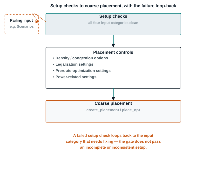
Some of the items below are entry gates — without them, placement cannot legally proceed at all. Others are optional strategy choices — deliberate decisions, not defaults you should let slide by unexamined. Both kinds need objective evidence, not a feeling that things are probably fine.
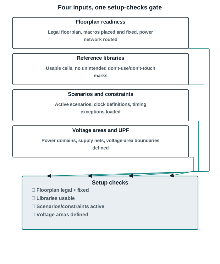
| Input / condition | Why placement needs it | Verification | Pass evidence | Failure symptom | Owner / source |
|---|---|---|---|---|---|
| Open, reproducible checkpoint | Placement builds on a specific saved design state; without one there is nothing to compare before/after against | current_block | Returns the expected block name | Wrong or no block open | Floorplan chapter's saved checkpoint |
| Legal floorplan / valid placement area | Coarse placement and legalization require real, non-overlapping site rows inside a defined core | report_utilization, GUI floorplan view | Utilization and core/die geometry match the Floorplan chapter's saved figures | Zero or nonsensical utilization; missing core area | Floorplan chapter |
| Standard-cell rows, sites, and fixed macros | Cells cannot legalize onto a grid that does not exist, and macro keepouts must already be honored | GUI floorplan view; report_placement for macro-adjacent violations | Rows visible across the core; macros show placement status fixed | Missing rows in part of the core; a movable macro | Floorplan chapter |
| Timing constraints and active scenarios | Timing-driven placement and every later timing report depend on real, intentional constraints, not a placeholder SDC | Spot-check a few paths with report_timing; confirm active scenarios | Constraints return sensible, non-default clock periods and exceptions | Default or missing clock definitions; no active scenario | Preparing the Design chapter |
| Clock definitions and logical DRC constraints | Congestion-, timing-, and buffering-aware placement all read these to know what to optimize toward | report_clock; report_constraints | Clocks and DRC limits (max transition, max capacitance, etc.) are present and reasonable | No clocks defined; DRC limits left at library defaults with no review | Preparing the Design chapter |
| Usable target / reference cells | Placement, buffering, and tie-cell insertion all need library cells that are not blanket don't-use | report_lib_cells or a library usability spot-check | Buffer, inverter, and tie cells are usable, not don't-use/don't-touch across the board | Optimization silently skips buffering or tie-cell insertion because no usable cell exists | Reference library setup |
| Placement blockages, bounds, and keepouts | Coarse placement and legalization must respect any area intentionally kept clear | GUI floorplan view; blockage list | Blockages match the Floorplan chapter's intent, with no unexplained gaps | A blockage silently missing or misplaced from the saved floorplan | Floorplan chapter |
| Scan/DFT inputs, or an explicit non-applicability decision | Coarse placement performs scan-chain optimization automatically when a SCANDEF is present — an easy side effect to miss | Check for a loaded SCANDEF or an explicit "no DFT" decision on record | A documented decision either way, not silence | Unexpected scan-chain reordering discovered after the fact | DFT / Preparing the Design chapter |
| Power domains, voltage areas, supply connectivity (if multivoltage) | IR-drop-aware placement and multivoltage buffering must know real voltage-area boundaries and supply availability | Power domain / voltage area list; UPF review | Domains and supply nets carried over match the Preparing the Design chapter | A voltage area with no legal supply net for buffering | Preparing the Design chapter |
| Switching activity (if power-driven decisions expected) | report_power and any power-aware placement decision need meaningful, not default, activity assumptions | Confirm an activity file or vectorless estimate is applied to the active scenario | A specific, intentional activity source is documented | Default/no activity, silently producing a meaningless power number | Design methodology / power scenario setup |
| Routing layers and congestion-estimation assumptions | Congestion-driven placement estimates routability against a specific layer and rule assumption | Routing-layer / NDR assumptions carried from Floorplan | Assumptions match what routing will actually use later | Placement congestion estimate based on different layers than routing will use | Floorplan chapter |
Preservation / dont_touch intent | Optimization must not disturb cells or nets deliberately protected earlier in the flow | report_attribute -name dont_touch on the intended set | Exactly the intended cells/nets carry the attribute, no more, no fewer | An unintended cell locked out of optimization, or an intended one left unprotected | Preparing the Design chapter |
| Baseline timing, power, and QoR capture; floorplan-stage utilization on record | Every comparison in this chapter — utilization change, timing movement, QoR-data comparison — needs a "before" to measure against. Utilization's real "before" is the floorplan-stage figure, not the trivial 0.0% read before any standard cell is placed. | report_qor -summary, write_qor_data labeled as the pre-placement run (Step 3); the floorplan-stage utilization figure carried forward from the previous chapter | A written or captured baseline exists before the first placement command runs | A later claim ("utilization improved," "timing got worse") with no baseline to check it against | This chapter, Step 3 of the worked example (QoR/timing); previous chapter's saved figure (utilization) |
| Saved rollback point | An option experiment or a bad run needs a known-good state to return to without redoing everything | save_lib return value | A checkpoint saved before any experimental option is tried | An irreversible experiment with no saved state to fall back to | This chapter |
Before placement starts
- Checkpoint reopens cleanly and
current_blockreturns the expected block.Evidence:current_blockoutput. - Floorplan-stage utilization is on record as the comparison baseline.Evidence: the achieved utilization number from the previous chapter, written down.
- Timing constraints and active scenarios are confirmed real, not placeholder.Evidence: a spot-check of a few paths via
report_timing. - Scan/DFT applicability is a documented decision, not an unexamined default.Evidence: a one-line note, either way.
- Power domains and voltage areas, if any, are carried over and understood.Evidence: the power domain list from the previous chapter.
- Preservation/
dont_touchintent is verified against the intended cell/net set.Evidence: an attribute query matching the intended list exactly.
Before optimization starts
- Coarse placement has completed and
report_placementshows a legal-ish starting point.Evidence:report_placementoutput from right after coarse placement. - Your project's policy on multibit register banking is known before letting any default flow bank silently.Evidence: a one-line note from design methodology, or an explicit decision to use the tool's default.
- Any nondefault application option you plan to enable (IR-drop-aware placement, congestion effort, trial clock tree) is a deliberate choice, reviewed against a first-pass report, not a default left untouched.Evidence: a one-line note on which options are enabled and why.
- Baseline timing, power, and QoR data are captured before the first optimization pass changes anything.Evidence:
write_qor_datalabeled as the pre-placement run, or equivalent saved reports.
Before a rerun or option experiment
- A checkpoint exists to roll back to if the experiment makes things worse.Evidence:
save_libreturn value before the experimental run. - The specific hypothesis behind the option change is written down, not just "try it and see."Evidence: a one-line note naming the option and the expected effect.
- Before/after evidence is planned for, not just the after: a
write_qor_datalabel exists for both states.Evidence: two distinct labeledwrite_qor_datacaptures, comparable viacompare_qor_data. - No option experiment will be accepted into the saved checkpoint without that before/after comparison being reviewed first.Evidence: the
compare_qor_data/view_qor_datacomparison, reviewed beforesave_lib.
Filling in the shape, one dependency at a time
1. The place_opt command and its five stages
place_opt performs coarse placement, physical optimization, and legalization in a single command, and by default runs all five of its internal stages in order: initial_place, where the tool merges clock-gating logic and performs coarse placement (and scan chain optimization, if a SCANDEF was read in); initial_drc, where the tool removes existing buffer trees and performs high-fanout-net synthesis and electrical DRC violation fixing; initial_opto, where the tool performs timing, area, congestion, and leakage-power optimization; final_place, where the tool performs incremental placement to improve timing and congestion, and legalizes the design; and final_opto, where the tool performs further optimization and legalization to improve timing and congestion.
The command supports multithreading, using the number of threads set by set_host_options -max_cores. Running it with no options at all executes every stage; that default behavior is the right starting point for a first pass on any new design.
2. Standalone placement and legalization
Everything place_opt does for coarse placement and legalization is also available as two separate commands: create_placement performs coarse placement (and, when a SCANDEF was read in, scan chain optimization), and legalize_placement executes detailed placement — moving cells onto real, legal, non-overlapping site positions without changing the netlist. Running these directly, instead of through place_opt, gives you control that the combined command does not expose as cleanly: legalizing only a named list of cells or a bounded region, for instance, rather than the whole design.
3. Staging place_opt with -from and -to
-from and -to let you run any contiguous subset of the five stages: if you do not specify -from, the tool begins from initial_place; if you do not specify -to, it continues through final_opto. This is how you re-enter the flow after fixing something upstream without re-running stages that already converged — for example, running only place_opt -from initial_drc on a design that already has a good coarse placement, to avoid re-placing it from scratch.
-list_only prints the five stage names without running anything, a quick way to confirm the exact stage names your release expects before scripting around them.
4. Timing-driven, buffering-aware, and congestion-driven placement
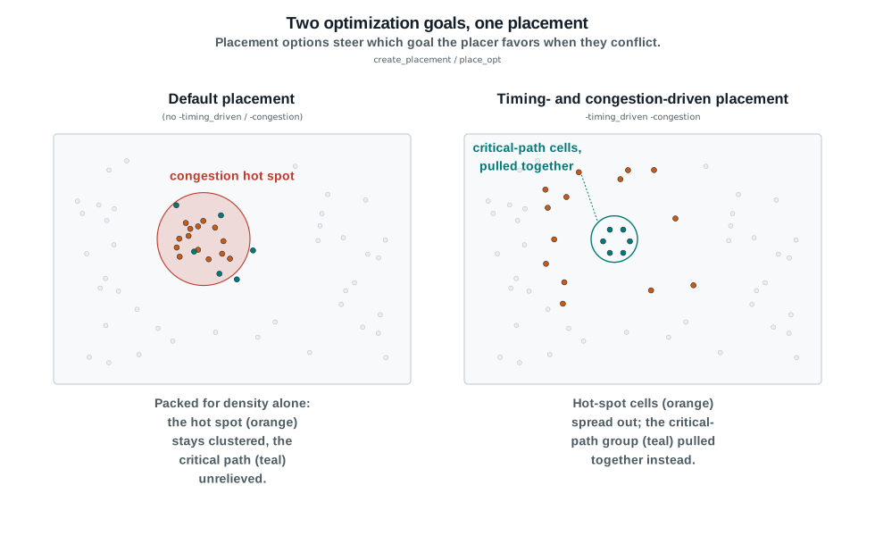
create_placement (and, through it, place_opt's coarse-placement behavior) supports several modes that change what coarse placement actually optimizes for. -timing_driven enables timing-driven placement outright. -buffering_aware_timing_driven uses an approximate timing model that estimates the effect of buffers that will be added later on long and high-fanout nets, without changing the netlist itself — intended specifically as a better starting point for later timing optimization, not a substitute for it. -congestion enables congestion-driven placement, with -congestion_effort (low, medium, or high) controlling how much CPU effort is spent avoiding routing hot spots; expect a real runtime cost at high effort.
5. Clock-gating cell optimization during placement
By default, place_opt merges clock-gating cells at the start of initial_place (or, when the Synopsys physical guidance flow is enabled, at the start of initial_opto). If merge_clock_gates has already been run beforehand, place_opt does not merge again. place_opt can go further: if the place_opt.flow.optimize_icgs application option is enabled, the tool performs clock-aware placement of critical clock-gating cells, builds a temporary clock tree specifically to identify timing-critical clock gates, and can split a clock-gating cell if the enable pin of the gate sits on a critical timing path.
6. Trial clock tree and clock-gate latency accuracy
place_opt uses ideal clock information by default. Setting the place_opt.flow.trial_clock_tree application option to true tells the tool to build a temporary clock tree and use propagated clocks during placement and optimization instead; Clock Tree Synthesis later removes this temporary tree and builds the real one. Independently, the tool estimates and updates clock-gate latencies throughout the place_opt flow by default, to make datapath and useful-skew optimization more accurate while clocks are still ideal — specifying real clock tree synthesis settings (buffers, inverters, nondefault routing rules) before running place_opt improves the accuracy of that estimate. A dont_estimate_clock_latency attribute, set with set_attribute on a specific clock-gate's clock pin, opts that one gate out of the estimate.
7. High-fanout synthesis and rebuilding buffer trees
During initial_drc, place_opt performs high-fanout net synthesis, building buffer trees for nets with too many loads for a single driver to handle well. By default this uses virtual routes; setting the place_opt.initial_drc.global_route_based application option to 1 switches it to use global routes instead, which for fragmented floorplans can improve timing and reduce congestion. Combined with place_opt.initial_place.two_pass set to true, the tool runs an integrated two-pass initial placement: wire-length-driven placement, a trial high-fanout synthesis pass whose results are discarded, then timing-driven placement that proceeds into global-route-based high-fanout synthesis for real.
After place_opt has run, if a specific buffer tree needs to be rebuilt to meet a requirement that changed later, create_buffer_trees rebuilds it explicitly — by default for all high-fanout nets, or for one named net with -from.
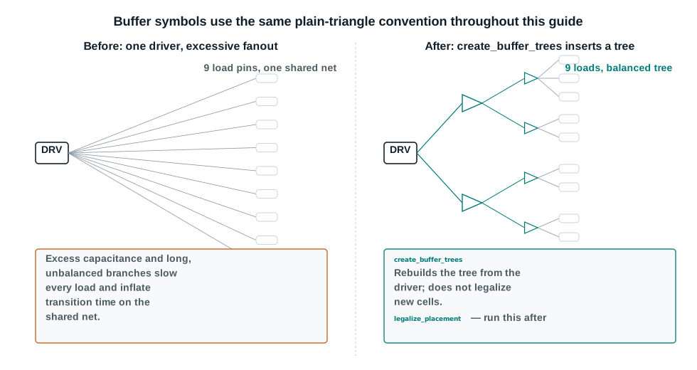
create_buffer_trees does not legalize the new cells itself — run legalize_placement after.8. Path optimization and nondefault routing rules for critical nets
Two further, independently-enabled behaviors improve timing QoR during place_opt. Setting place_opt.flow.do_path_opt to true turns on path optimization — an incremental capability focused specifically on improving individual timing paths' QoR. Setting place_opt.flow.optimize_ndr to true lets the tool apply nondefault routing rules to timing-critical nets during preroute optimization, and guide the router to honor those assignments later as soft constraints.
9. IR-drop-aware placement
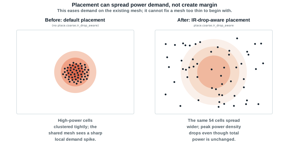
During placement, the tool can use the voltage (IR) drop values of cells to identify areas of high power density and spread those cells out, reducing local density. This requires an external voltage-drop analysis source — RedHawk Fusion, set up and run separately — that this guide names but does not cover in depth, since it lives outside the ICC2 User Guide's own scope for this chapter. The ICC2-side procedure is: run place_opt -to final_place to get through final placement; perform static or dynamic voltage-drop analysis with analyze_rail -voltage_drop (after the external setup); enable place.coarse.ir_drop_aware; and rerun with place_opt -from final_place to let the tool use the voltage-drop values on the next pass.
10. Concurrent clock and data (CCD) optimization
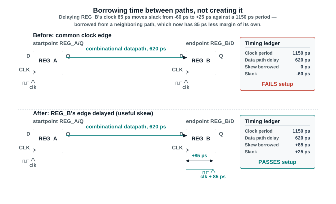
Concurrent clock and data optimization applies useful-skew techniques during the final optimization stage — adjusting clock arrival times at registers to take advantage of positive slack elsewhere in the path. It is enabled by default during final_opto; setting place_opt.flow.enable_ccd to false turns it off. The clock-latency adjustments it derives are stored as offsets (via set_clock_latency -offset and set_clock_balance_point -offset), visible with write_script -format icc2, but not captured in an SDC written with write_sdc. To use CCD meaningfully, the same scenarios active for clock_opt should be active for place_opt, and the tool needs either a trial clock tree (place_opt.flow.trial_clock_tree or place_opt.flow.optimize_icgs set true) or accurate ideal clock latencies on every clock-gating and sequential cell.
11. Physical guidance from Design Compiler
When starting placement from a Design Compiler Graphical placement instead of from scratch, ICC2 can use that placement as a starting point — reducing placement runtime and improving correlation between the two tools. The DC-side netlist transfers as Verilog with constraints; physical information (die area, site rows, tracks, port locations, macro and cell placement, route guides, prerouted nets, and placement blockages) transfers by reading a DC-generated DEF file with read_def -add_def_only_objects {cells} -convert_sites. Physical constraints DEF does not carry — voltage area definitions, layer constraints, special route guides with utilization, and special blockages with blocked layers — must be applied separately in a Tcl file. Setting place_opt.flow.do_spg to true before running place_opt enables this Synopsys physical guidance (SPG) flow.
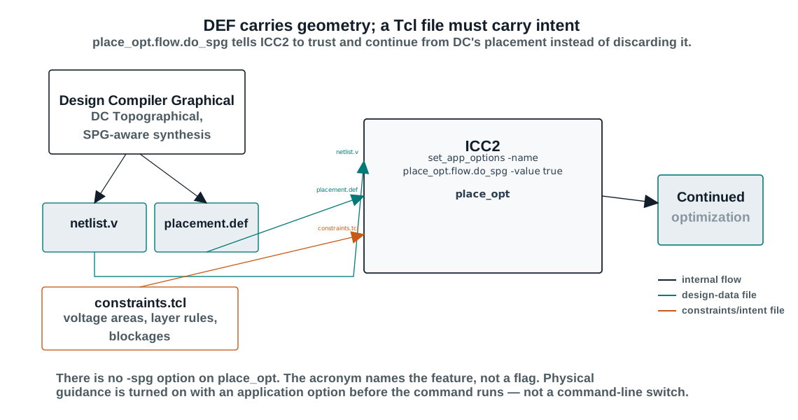
-spg option on place_opt: the ICC2 box shows the actual mechanism, set_app_options -name place_opt.flow.do_spg -value true run before place_opt. SPG names the feature; it is not a command-line flag. Treating the DEF alone as "the constraints" is the most common gap in this flow.12. Multibit register optimization
ICC2 can combine (bank) single-bit registers, or smaller multibit register banks, into equivalent larger multibit register cells — merging only registers that share the same timing constraints, and copying those constraints to the resulting bank. Banking reduces area (shared transistors, optimized transistor-level layout), total clock tree net length, and clock tree buffer count and power. The tool can also split (debank) a multibit register into smaller banks or single-bit cells if doing so improves total negative slack, and on libraries with mixed-drive-strength multibit cells, it can rewire a violating path through a higher-drive-strength bit of an existing bank.
Banking can run integrated inside place_opt (enable place_opt.flow.enable_multibit_banking, optionally place_opt.flow.enable_multibit_debanking) or as discrete steps: identify_multibit finds banking opportunities and either applies them directly (-apply) or writes a script of create_multibit commands to review first (-output_file); split_multibit reverses a bank, by name, by slack threshold, or by path group; report_multibit reports what actually exists.
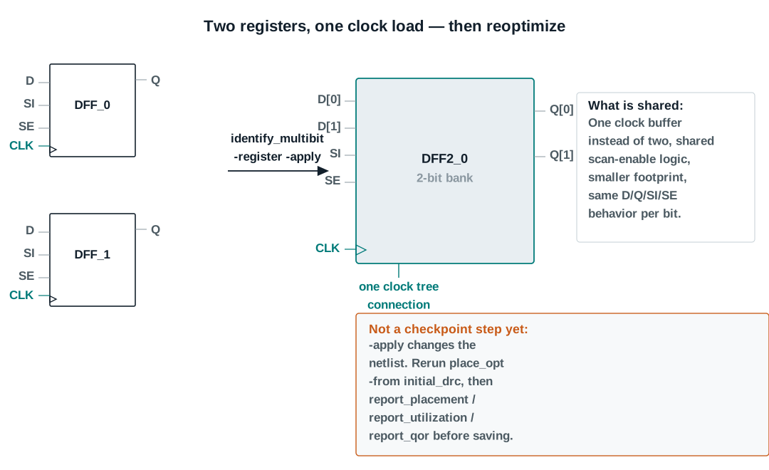
-apply changes the netlist, so it is not itself a checkpoint: rerun place_opt -from initial_drc and take fresh reports before treating the result as saved.13. Magnet placement and refining placement
magnet_placement pulls the standard cells connected to a fixed anchor object — a fixed macro, a macro pin, or an I/O port — close to it, which can improve congestion around a complex floorplan or improve timing for a specific cluster of logic. Best run before standard-cell placement, it accepts a magnet object plus an optional -cells list restricting exactly which cells get pulled; cells form a contiguous data path from the magnet, or nothing moves. -logical_levels controls how many logic levels from the magnet are considered, and -stop_by_sequential_cells / -stop_on_sequential_cells stop the pull at a register boundary.
After a placement exists, refine_placement performs incremental congestion-optimizing placement on the whole design (or, with -coordinates, one bounded region) without touching the netlist — useful for a targeted congestion cleanup pass after the main place_opt flow has otherwise converged.
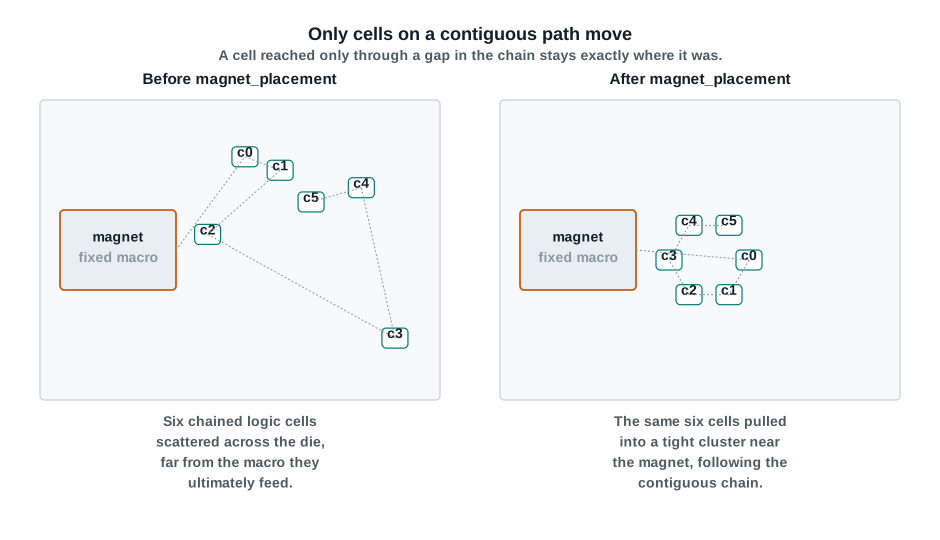
14. Multivoltage-aware placement and optimization
Placement and optimization automatically account for multivoltage constraints. During placement, the tool places cells within their associated voltage area, and places level shifters and isolation cells close to voltage-area boundaries. During optimization, when the tool needs to insert a buffer, it analyzes the power states of the driver and loads' supplies (from the UPF power-state table or power-state groups) and chooses a buffering supply that avoids introducing a new multivoltage violation, preferring single-rail buffers over dual-rail ones to save power, area, and improve routability. check_bufferability answers, for a specific net segment and voltage area, whether a legal buffer actually exists to insert.
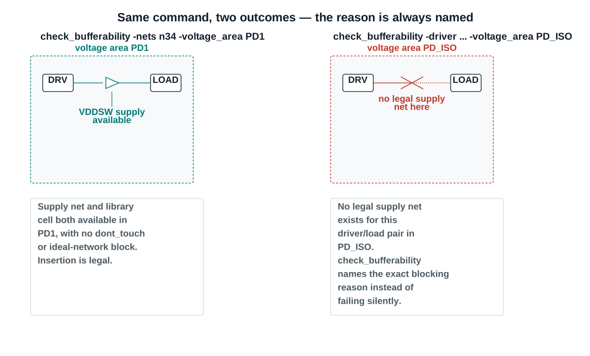
check_bufferability gives the specific reason, not just pass or fail.15. Analyzing the result: utilization, placement QoR, and status
report_utilization reports achieved density from real geometry, exactly as in the previous chapter, optionally scoped to specific objects with -of_objects or to a named configuration created with create_utilization_configuration. report_placement is the placement-specific QoR report: by default it reports total half-perimeter wire length for all nets plus any placement violations, and supports narrower views — physical hierarchy violations, voltage-area violations, hard-macro overlap, and more — through its many options. Every cell instance carries a placement status — unplaced, placed, fixed, legalize_only, or locked — queryable with get_attribute and settable with set_placement_status, which is how you lock a cell's location against further movement by the tool while still allowing manual edits.
16. Diagnosing issues optimization could not fix
Two commands exist specifically to explain a stubborn problem rather than fix it directly. check_bufferability analyzes whether a net segment can be buffered at all — checking for available supply nets in the target voltage area, suitable library cells, and settings (an ideal-network or don't-touch constraint) that block buffering — and reports why, not just whether. analyze_design_violations generates a categorized, descending-severity report of violations that optimization could not fix, by type (max_trans, setup, hold, static_noise, or only_lib for library settings limiting optimization), which is the right first stop when a design comes out of place_opt with violations that a re-run does not seem to improve.
The commands worth knowing cold
Every card below follows the same eight-point shape used throughout this guide, and every syntax line has been checked against the ICC2 Tcl command reference for this release. Where your installed release differs, trust man <command> over this page.
place_opt
Places and optimizes the current design in one command, five stages by default.
- What it isRuns coarse placement, DRC/buffering fixup, optimization, incremental placement, legalization, and a final optimization pass, in order.
- Why you run itIt is the default, complete path from a legal floorplan to a fully placed, optimized, legalized design.
- When in flowFirst in this chapter, immediately after the previous chapter's saved checkpoint is reopened.
- Exact Tcl
icc2_shell> place_opt - What ICC2 changesPlaces every standard cell, optimizes for timing/area/congestion/leakage, performs incremental re-placement, and legalizes the final placement.
- What to read back — proof it took effect
report_placementfor wire length and violations;report_utilizationcompared against the floorplan-stage figure. - Trap
-fromand-tomust respect stage order — the start stage cannot come after the end stage in the fixed sequenceinitial_place,initial_drc,initial_opto,final_place,final_opto. - If you skip itStandard cells stay unplaced; nothing downstream — CTS, routing — has real cell geometry to build against.
create_placement
Performs standalone coarse placement, with timing- and congestion-driven modes.
- What it isThe standalone coarse-placement command
place_optcalls internally duringinitial_place, runnable on its own for direct control. - Why you run itTo control coarse placement explicitly — effort level, timing- or congestion-driven mode — separate from the rest of the
place_optflow. - When in flowAn alternative first step to
place_opt, aftermerge_clock_gateshas already run. - Exact Tcl
icc2_shell> create_placement -timing_driven -congestion \ -congestion_effort medium - What ICC2 changesGives every standard cell an approximate, legal-ish location, optimizing for the requested criteria.
- What to read back
report_placementfor wire length and any early violations, before optimization or legalization has run. - TrapIf a block contains scan chains annotated from a SCANDEF, coarse placement also performs scan chain optimization automatically — a side effect easy to miss when troubleshooting an unexpected scan-chain change.
- If you skip itNo standard cell has a location yet, and every later command that depends on placement has nothing to operate on.
legalize_placement
Executes detailed placement, moving cells onto real, legal, non-overlapping sites.
- What it isDetailed placement: legalizes an existing coarse or optimized placement onto real site-grid positions, without changing the netlist.
- Why you run itCoarse placement and optimization can leave cells in near-legal, overlapping, or off-grid positions that must be resolved before the design is real.
- When in flowAfter coarse placement or any optimization pass that could have disturbed legality;
place_optcalls this internally duringfinal_place. - Exact Tcl
icc2_shell> legalize_placement - What ICC2 changesMoves cells onto legal, non-overlapping site positions with minimal disturbance; with
-cells, legalizes only the named cells and leaves every other cell unchanged — but only after settingplace.legalize.legalize_only_selected_cellstotrue(or runningplace_eco_cells -cells -legalize_onlyfirst). This is supported directly under the standard legalizer — see the trap below for the advanced-legalizer restriction. - What to read back
report_placementfor any remaining placement violations after legalization completes. - TrapThe
-cellsoption is not supported when the advanced legalizer is enabled — confirm which legalizer mode is active before relying on cell-scoped legalization. - If you skip itA design can look placed in the layout view while still carrying illegal, overlapping, or off-grid cells that later stages will reject.
reset_placement
Unplaces every non-fixed, non-locked cell in the core area.
- What it isReverts every cell currently in the
placedstatus back tounplaced; cells markedfixedorlockedare left untouched. - Why you run itTo discard a placement attempt cleanly and start coarse placement over, without losing deliberately fixed cells.
- When in flowRarely mid-chapter; mainly a recovery step when a placement attempt needs to be abandoned.
- Exact Tcl
icc2_shell> reset_placement - What ICC2 changesSets every cell with status
placedback tounplacedacross the core area. - What to read backA placement-status query across the design confirming which cells actually reverted and which stayed fixed or locked.
- TrapThis does not touch cells marked
fixedorlocked— if you intended a full reset, check for cells you fixed earlier in the session that will silently survive this call. - If you skip itN/A — this is a recovery command, not a required step in the default flow.
merge_clock_gates
Merges integrated clock-gating (ICG) cells in clock trees, without changing logic.
- What it isMerges ICG cells within each clock tree that have the same type and identical enable-pin logic, for all currently defined clocks in all active modes by default.
- Why you run itFewer, better-placed clock-gating cells reduce clock tree size and power;
place_optdoes this automatically unless it has already been done. - When in flowBefore
create_placement, when running placement as standalone steps rather than throughplace_opt. - Example
icc2_shell> merge_clock_gates - Check your release
merge_clock_gateshas no option to scope it to one clock — it merges eligible clock-gating cells across every clock tree. Runmerge_clock_gates -helpagainst your release before you script anything narrower. - What ICC2 changesMerges eligible ICG cells for every clock's tree, without affecting the design's logic. There is no option to scope this to a single named clock — it runs chip-wide.
- What to read backA clock-gating cell count before and after, or a spot-check of a merged cell's enable-pin logic against its pre-merge sources.
- TrapIf you run this before
create_placement, rememberplace_optwill not merge again — running both is not redundant-but-harmless work, it is simply a no-op the second time. - If you skip itWhen running standalone
create_placement(notplace_opt), clock-gating cells are never merged automatically — a design keeps more, smaller ICG cells than necessary.
magnet_placement
Pulls the standard cells connected to a fixed anchor object close to it.
- What it isPulls cells forming a contiguous data path from a specified magnet object — a fixed macro, macro pin, or I/O port — toward that object.
- Why you run itTo reduce local congestion around a complex floorplan, or improve timing for a specific cluster of logic, by shortening its wiring to a fixed anchor.
- When in flowBest run before standard-cell placement; can also be used later as a targeted, localized fix.
- Example
icc2_shell> magnet_placement nimbus8_ddrphy - Check your releaseCheck
magnet_placement -helpon your release for a logical-level limit and a stop-at-sequential-cell option before relying on either. - What ICC2 changesMoves the qualifying, connected cells closer to the magnet object; cells not on a contiguous path from the magnet do not move.
- What to read backA congestion or cell-density map, or
report_placement, before and after.magnet_placementhas a preview-only mode; confirm its exact option name withmagnet_placement -helpon your release before you rely on it. - TrapCells reached only through a gap in the data path — not truly contiguous with the magnet — do not move, even if they look logically related; the tool follows connectivity, not proximity or intuition.
- If you skip itLogic connected to a fixed macro is placed wherever ordinary placement decides, which is not always close to the macro it depends on most.
refine_placement
Performs incremental, congestion-optimizing placement without touching the netlist.
- What it isIncremental placement focused on congestion optimization, run on the whole design by default or a bounded region with
-coordinates. - Why you run itFor a targeted congestion cleanup pass after the main flow has otherwise converged, without re-running full placement and optimization.
- When in flowAfter
place_opt, when a congestion map still shows a localized problem worth addressing directly. - Example
icc2_shell> refine_placement - Check your releaseCheck
refine_placement -helpon your release for a congestion-effort or perturbation-level option before you script around one. - What ICC2 changesAdjusts cell positions to relieve congestion; does not modify the netlist.
- What to read backA congestion map before and after, and
report_placementto confirm no new violations were introduced. - Trap
-coordinatesrestricts changes to one rectangle, but the reference documentation itself warns this region-based refinement can cause timing or congestion degradation if the region is not properly chosen — whole-design refinement is the recommended default. - If you skip itA localized congestion hot spot that
place_opt's global optimization did not fully resolve stays as-is.
identify_multibit
Finds groups of registers or MV cells that can be replaced by multibit equivalents.
- What it isIdentifies banking opportunities among registers (
-register) or isolation/level-shifter cells (-mv_cell), and either applies them or writes a reviewable script. - Why you run itTo bank single-bit registers into multibit cells as a discrete, reviewable step, instead of letting
place_optbank silently. - When in flowAfter coarse placement, before running
place_opt -from initial_drcto optimize the banked design. - Example
icc2_shell> identify_multibit -register - Check your releaseCheck
identify_multibit -helpon your release for an apply-directly option and a slack-threshold option before you build a script around either. - What ICC2 changesReplaces qualifying groups of single-bit registers with equivalent multibit register cells directly, or writes the equivalent
create_multibitcommands to a file for review first, depending on how the command is invoked. - What to read back
report_multibitfor what was actually banked, compared against what you expected. - TrapBy default this performs DFT optimization that repartitions scan chains to increase banking opportunities — use
-no_dft_optif scan-chain structure must not change. - If you skip itRegisters stay single-bit, at whatever area, clock-net, and clock-buffer cost that implies for this design's register count.
split_multibit
Splits a multibit register bank into smaller banks or single-bit cells.
- What it isReverses banking, on a named cell, on cells with slack worse than a threshold, or on cells within a named timing path group.
- Why you run itWhen multibit banking has put a violating path through a bank in a way that hurts total negative slack more than banking helped.
- When in flowAfter banking and a subsequent optimization pass shows a specific bank hurting timing.
- Exact Tcl
icc2_shell> split_multibit -slack_threshold -1 - What ICC2 changesSplits the targeted multibit cells into the specified smaller cells (or single-bit cells by default), only for cells that were created by
create_multibitoridentify_multibit. - What to read back
report_multibitre-run afterward, and the specific paths' slack re-checked withreport_timing. - TrapThis only splits cells the tool itself banked — a multibit cell that existed in the original netlist, never created by banking, cannot be split with this command.
- If you skip itA bank that is hurting a specific violating path stays banked, with no automatic correction elsewhere in the flow.
check_bufferability
Checks whether a net segment can actually be buffered, and explains why or why not.
- What it isChecks for an available buffering supply net, suitable library cells, and blocking settings (ideal-network, don't-touch) on a specified net segment.
- Why you run itWhen optimization reports a net it could not buffer, this explains the specific reason instead of leaving you to guess.
- When in flowWhenever a specific net's bufferability is in question, most often while diagnosing a stubborn optimization result.
- Example
icc2_shell> check_bufferability -nets n34 -voltage_area PD1 - Check your releaseCheck
check_bufferability -helpon your release for a verbose-output option. - What ICC2 changesNothing — this is a read-only analysis.
- What to read backThe command's own information message: which library cells and supply nets are usable, or a specific reason buffering is impossible.
- TrapA net can be bufferable in one voltage area and not another — always specify
-voltage_areadeliberately rather than relying on a default that may not match the segment you actually care about. - If you skip itAn unbufferable net stays a mystery, and troubleshooting time goes into re-running optimization instead of understanding the actual blocker.
create_buffer_trees
Rebuilds buffer trees for high-fanout nets after place_opt has run.
- What it isRemoves and rebuilds buffer trees for high-fanout nets, by default for every such net, or a named one with
-from. - Why you run itTo meet a requirement — timing, area, or DRC — that changed after
place_opt's own automatic buffer-tree construction duringinitial_drc. - When in flowAfter
place_opt, when a specific net's buffering needs to be redone explicitly. - Exact Tcl
icc2_shell> create_buffer_trees -from n_highfanout_1 - What ICC2 changesRemoves the existing buffer tree for the targeted net(s) and rebuilds it from the driver outward.
- What to read backA timing and DRC check on the affected net, comparing before and after the rebuild.
- TrapThis is a targeted, explicit rebuild — it is not what runs automatically during
place_opt's owninitial_drcstage, and running it unnecessarily can undo buffering decisions optimization already made well. - If you skip itThe buffer tree
place_optoriginally built for that net stands as-is, even if downstream requirements have since changed.
report_placement
Reports placement QoR: wire length and placement violations for the current block.
- What it isBy default, reports total half-perimeter wire length for all nets and any placement violations present in the design.
- Why you run itIt is the placement-specific proof that the design converged, distinct from a general utilization or timing report.
- When in flowAfter
place_opt(or standalone placement and legalization), and again after any later refinement. - Example
icc2_shell> report_placement - Check your releaseCheck
report_placement -helpon your release for options that narrow the report to one violation category. - What ICC2 changesNothing — this is a read-only report.
- What to read backThe reported wire length and violation counts; the design's specific violation categories still need reading in the full default report unless a narrowing option is separately confirmed.
- TrapA single-row-height violation on a standard cell is common enough after coarse placement that the tool does not report it by default — do not assume zero reported violations means zero placement imperfection at every stage.
- If you skip itYou are trusting that placement converged without ever actually checking, the same "looks fine" failure mode this guide keeps warning against.
set_placement_status
Sets the placement status of a cell or port, controlling whether the tool may move it.
- What it isSets a cell or port's placement status to
unplaced,placed,fixed,legalize_only, orlocked. - Why you run itTo lock in a placement decision — a cell whose location a later reviewer or later optimization pass must not silently disturb.
- When in flowAfter a placement is confirmed correct, most often near the end of the chapter, before handing off to Clock Tree Synthesis.
- Exact Tcl
icc2_shell> set_placement_status fixed [get_cells INST_1] - What ICC2 changesSets the named status on the specified cells or ports; a
fixedcell can still be sized during optimization, but not moved by it. - What to read backA placement-status query on the same objects, confirming the status actually took, per the naming discrepancy noted in Analyzing the result.
- TrapA
fixedcell can still be resized by the tool; if a cell's size must not change either, an additionaldont_touchattribute is required — fixed placement status alone is not a full lock. - If you skip itEvery cell remains movable by later commands, including ones run well after you considered its placement final.
Nimbus‑8: placing and optimizing a teaching design end to end
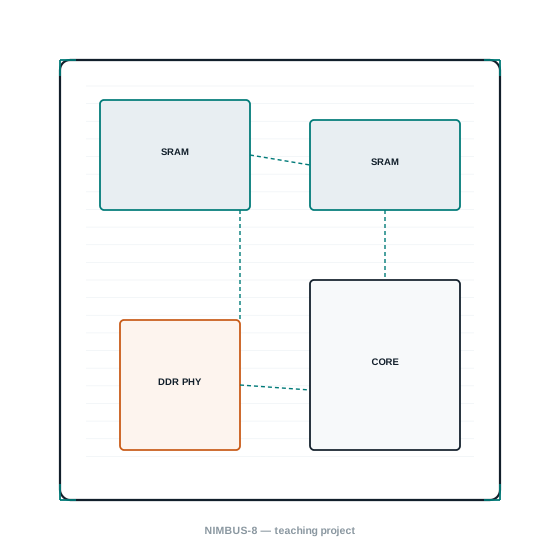
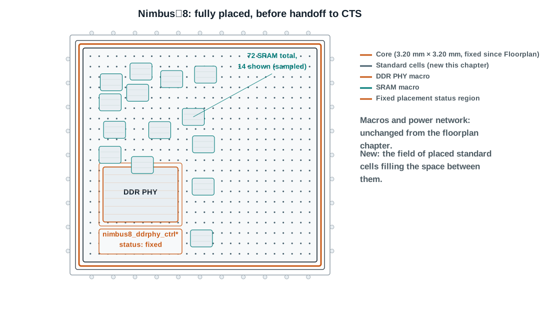
Continuing from the previous chapter's saved checkpoint: a 3.20 mm × 3.20 mm core at 81.9% floorplan-stage utilization, 9.90 million standard cells, 72 SRAM macros, one DDR PHY hard macro, a compiled power network, and assigned pins. This chapter runs the IR-drop-aware placement procedure end to end on Nimbus‑8's own supply, and banks a portion of its register count into multibit cells.
Step 1 — reopen the checkpoint
icc2_shell> open_lib ../libs/nimbus8_lib
icc2_shell> current_block
{nimbus8_top}
Proof: current_block returns the same block the previous chapter saved, confirming this chapter is building on a validated floorplan, not a fresh unlinked design.
Step 2 — merge clock-gating cells before placement
icc2_shell> merge_clock_gates
/* run standalone since this worked example uses create_placement directly, not place_opt, for step 4 */
Proof: a clock-gating cell count taken before and after shows a reduction, with no change to the design's logical behavior.
Step 3 — confirm a clean pre-placement start and capture the QoR baseline
icc2_shell> report_utilization -verbose
Utilization: 0.0%
icc2_shell> report_qor -summary
Proof: the 0.0% reading here is measured standard-cell utilization — expected and correct, since Step 4's coarse placement has not run yet, so no standard cell has a location. It is a sanity check that this run starts clean, not the utilization figure Step 9 compares against; the utilization comparison this chapter cares about is against the floorplan-stage planned figure of 81.9% (the previous chapter's macros-plus-budgeted-cells figure over the fixed 3.20 mm × 3.20 mm core), captured before any Placement and Optimization command ran. The report_qor -summary baseline captured here is what Step 9's post-optimization QoR is measured against — a real "before," not an assumption.
Step 4 — coarse placement, timing- and congestion-driven
icc2_shell> create_placement -timing_driven -congestion \
   -congestion_effort medium
Proof: report_placement run at this point shows a legal-ish, if not yet optimized, placement with a reasonable total wire length for a 9.90-million-cell design at this utilization.
Step 5 — bank Nimbus‑8's register file into multibit cells, before optimization
icc2_shell> identify_multibit -register -apply -slack_threshold 0
icc2_shell> report_multibit
Proof: report_multibit lists the banked cells, confirming only registers with slack at or above the threshold were combined — nothing on a genuinely tight path was pulled into a bank without headroom to spare.
Step 6 — run place_opt through final placement
icc2_shell> place_opt -from initial_drc -to final_place
Proof: starting from initial_drc means this run both legalizes and optimizes the banked netlist from Step 5 — it is the required reoptimization pass, not a separate optional step. Stopping deliberately at final_place, rather than letting final_opto run immediately, leaves the design legalized and ready for the IR-drop-aware placement setup in the next step, per the ICC2 User Guide's own procedure for this feature.
Step 7 — enable IR-drop-aware placement and rerun
/* voltage-drop analysis itself requires RedHawk Fusion, set up separately and out of this guide's scope; */
/* the two icc2_shell-side steps below are what the ICC2 User Guide documents for this release */
icc2_shell> set_app_options -name place.coarse.ir_drop_aware -value true
icc2_shell> place_opt -from final_place
Proof: a before-and-after voltage-drop heatmap (from the external analysis source) shows the previous power-density hot spot spread over a wider area, and report_placement confirms no new placement violations were introduced by the rerun.
Step 8 — check tie cells
icc2_shell> report_multibit
icc2_shell> add_tie_cells
Proof: place_opt inserts tie cells automatically where it creates constant-driven pins during optimization; running add_tie_cells afterward catches anything left undriven — a return of no new insertions is itself the pass evidence.
Step 9 — check placement QoR and utilization against the baseline
icc2_shell> report_placement
icc2_shell> report_utilization -verbose
Utilization: 79.4%
Proof: compare this reading against the floorplan-stage planned baseline (81.9%) named at the top of this worked example, not against Step 3's 0.0% (that was a pre-placement sanity check, not a utilization baseline — standard cells had no location yet). Here the illustrative before/after shows utilization moving from the floorplan-stage planned 81.9% down to a measured 79.4% — consistent with Step 5's banking reducing cell count and therefore occupied area inside the same fixed 3.20 mm × 3.20 mm core, not a contradiction of it. report_placement shows no unresolved violations. Never assume utilization is unchanged after a netlist-changing operation like banking; measure it.
Step 10 — lock the DDR PHY's companion logic before CTS
icc2_shell> set_placement_status fixed [get_cells nimbus8_ddrphy_ctrl*]
icc2_shell> get_attribute -objects [get_cells nimbus8_ddrphy_ctrl_top] -name status
Proof: the status query confirms fixed took effect on the queried cell, protecting this cluster's now-converged placement from being disturbed by clock tree synthesis's own optimization passes next chapter.
Step 11 — checkpoint
icc2_shell> save_lib nimbus8_lib
Saving library 'nimbus8_lib'
1
Checkpoint / rollback point: this is the placed, optimized, reoptimized-after-banking design Clock Tree Synthesis will build on. Treat the return value 1 as confirmation, the same discipline carried from every previous chapter.
What to look for in the GUI
As in every chapter so far, no screenshots are supplied — the habit of looking with intent outlasts any static picture. ICC2's GUI offers three map modes purpose-built for this chapter's work: the global route congestion map, the cell density map, and the pin density map. After each major step above, open the layout view and check:
- After coarse placement: does the cell density map show any obviously empty or overcrowded region, before optimization has had a chance to smooth it out?
- After
initial_optoor a fullplace_optpass: does the global route congestion map show any hot spot you did not expect, given the floorplan's macro layout? - After IR-drop-aware placement: does the same region that showed high power density before now show a visibly wider spread of high-power cells?
- After multibit banking: spot-check a few banked cells in the layout view — do they sit in a sensible location relative to where their original single-bit registers were?
- After locking cells with
set_placement_status fixed: confirm in the GUI (or with a status query) that exactly the intended cluster, and nothing wider, was affected.
Reading proof, not just running commands
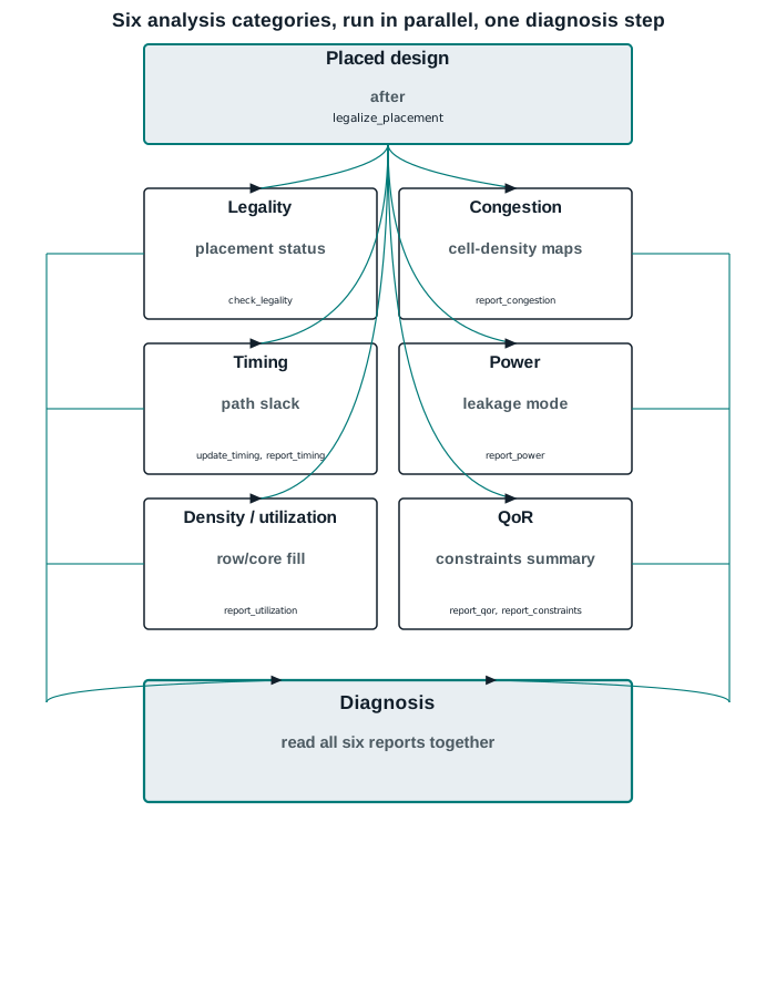
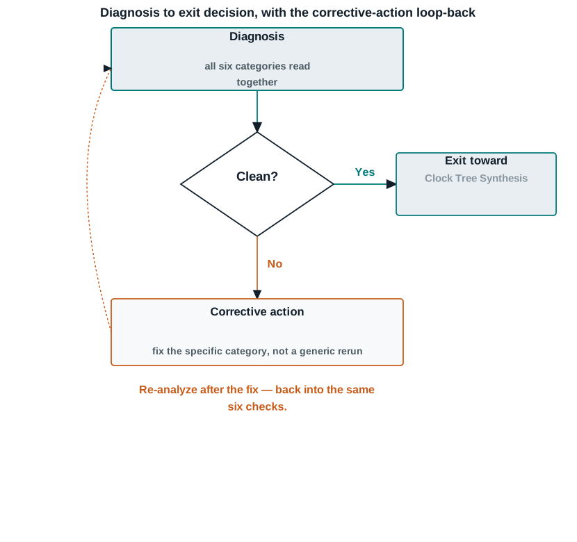
| Report | What it proves | Red flag to look for |
|---|---|---|
report_placement | Total wire length and placement violations, the core placement-QoR proof | Any nonzero violation count left unreviewed, especially hard-macro overlap or physical-hierarchy violations |
report_utilization -verbose | Achieved density held steady from the floorplan-stage figure | A utilization figure that shifted from the floorplan-stage baseline with no explanation |
report_multibit | Exactly which registers were banked, and at what slack threshold | A bank that includes a cell on a path you know is tight, despite a slack-threshold setting meant to exclude it |
Placement-status query (get_attribute) | Which cells are fixed or locked, and that the set matches intent | A cell fixed unintentionally, blocking a later optimization pass from a legitimate improvement |
check_bufferability | Whether a specific net segment can be buffered, and the exact reason if not | A "cannot insert buffers" result with no voltage-area or supply-net explanation checked |
analyze_design_violations | A categorized, prioritized list of violations optimization could not fix on its own | Re-running place_opt unchanged, hoping the same violations resolve without new information |
report_qor (named here, detailed in the Timing Analysis User Guide) | Overall QoR statistics for the block, beyond placement alone | Treating a clean placement report as equivalent to a clean overall QoR report |
Reading timing at the placement stage, not skipping it
Timing is automatically updated whenever a command needs it — report_timing included. Use update_timing explicitly when you want a fresh, known-current timing snapshot before comparing two moments in the flow, rather than relying on an implicit update buried inside whatever you run next.
update_timing
Explicitly refreshes timing information for the current design.
- What it isAn explicit timing update; incremental by default (updates only out-of-date information).
- Why you run itTo guarantee timing is current before you take a reading you intend to compare against a later one — not to make timing "more correct" than an automatic update would.
- When in flowRight before capturing baseline timing, and again right before capturing post-optimization timing, so both readings are on the same footing.
- Example
icc2_shell> update_timing - Check your releaseCheck
update_timing -helpon your release for a full-update flag before you rely on one. - What ICC2 changesRecomputes timing analysis data; changes no placement or netlist state.
- What to read backNo direct report of its own — it prepares the design for
report_timing,report_qor, andreport_constraintsto read. - TrapAn explicit update costs real runtime beyond what an implicit, automatic update would — use it only when you specifically distrust the incremental result, not as a reflexive habit before every report.
- If you skip itUsually nothing — the next timing-dependent command updates it for you. The risk is only in a before/after comparison where one side updated implicitly at a different moment than the other.
Reading one timing path before running anything
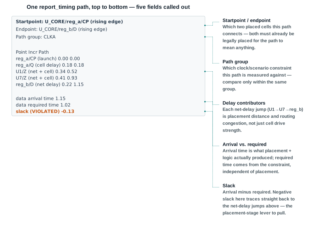
Before the commands, know what a single reported path is telling you. Every report_timing path names a startpoint (where the signal launches, usually a register's clock pin or an input port) and an endpoint (where it is captured, usually a register's data pin or an output port), grouped into a path group. The report gives an arrival time (when the signal actually gets there, accumulated delay along the path) and a required time (the latest, or earliest, it is allowed to arrive, set by the clock period and any constraint). Slack is required time minus arrival time for a max-delay (setup) path; a positive slack means the path passes with that much margin, a negative slack means it is late by that much.
| Field | Illustrative value | What it means |
|---|---|---|
| Startpoint | nimbus8_regfile/bank3_reg[12]/CP | Launch flop's clock pin — the path's origin |
| Endpoint | nimbus8_alu/acc_reg[12]/D | Capture flop's data pin — the path's destination |
| Path group | sys_clk | Which clock's constraints govern this path |
| Arrival time | 3.42 ns | Accumulated delay from launch to this point |
| Required time | 3.60 ns | Latest arrival the clock period and constraints allow |
| Slack | +0.18 ns | Passing, with 0.18 ns of margin |
| Step | Command or report | What it answers | Red flag |
|---|---|---|---|
| 1 | update_timing (when an explicit refresh is needed) | Is this timing snapshot current? | Comparing a stale reading against a fresh one without realizing it |
| 2 | report_timing | What are the worst paths, and by how much do they pass or fail? | A negative-slack path with no owner or explanation |
| 3 | report_qor -summary | What is the overall setup/hold/design-cost picture, not just the single worst path? | A worst-path fix that leaves total negative slack (TNS) barely moved |
| 4 | report_constraints | Are there logical DRC violations — max transition, max capacitance, max/min delay, min pulse width, min period? | Any DRC violation left unreviewed, even if timing itself looks clean |
| 5 | Compare against the pre-placement baseline (Step 3 of the worked example) | Did placement and optimization move timing in the direction you expected? | Worst slack improved while total negative slack got worse — a sign of localized, not systemic, improvement |
| 6 | Classify any regression before rerunning anything | Is this a placement problem, a constraint problem, a library/cell problem, or a limit optimization cannot fix? | Rerunning place_opt unchanged, hoping a regression resolves without new information |
Reading a power report without comparing apples to oranges
Power is calculated and reported with report_power. Before running it, know which leakage-power calculation method is active, since it changes the numbers you get back.
| Mode | Basis |
|---|---|
average | Equal weighted probabilities for all states |
unconditional | The library's default_cell_leakage_power or cell_leakage_power attribute |
state (default) | Weighted sum of each cell state's condition, from state-dependent leakage characterization and static probability; falls back to unconditional if that characterization data is not available |
off | Leakage power is not reported |
icc2_shell> set_app_options -name power.leakage_mode -value average
To include composite current source (CCS) receiver-model capacitance in power analysis and reporting, set power.use_ccs_rcv_cap to true.
Reading a power report
A default power report names the mode, corner, and scenario it was computed in, the voltage and temperature used, the voltage/temperature/power units, cell leakage power, and a breakdown by power group with leakage power, total power, and percentage of total for each group.
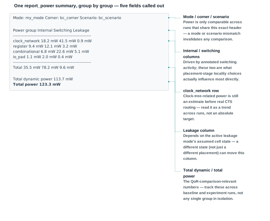
| Field | Illustrative value | What it means |
|---|---|---|
| Mode / Corner / Scenario | my_mode / bc_corner / bc_scenario | Which active scenario this report was computed for — power differs by scenario |
| Voltage / Temperature | 1.16 V / 125 °C | The operating point this scenario represents |
| Cell Leakage Power | 5,125,495.58 μW | Total leakage across all cells, under the active leakage mode |
Power group: clock_network | 0.65% of total | Power attributed to clock-network cells (or pins, if pin-based reporting is enabled) |
Power group: register | 31.67% of total | Power attributed to sequential/register cells |
Power group: combinational | 67.66% of total | Power attributed to combinational logic |
| Total | 5.13e+03 mW | Sum of leakage and dynamic power across all groups |
Power groups
Running report_power without a specific cell list reports the default power groups (io_pad, memory, black_box, clock_network, register, sequential, combinational). Custom power groups — instance-based or library-cell-based — are created with set_power_group, and the report includes both default and user-defined groups. If a cell qualifies for more than one group, its reporting group is decided by precedence: an instance-level set_power_group assignment first, then a library-cell-level assignment, then the cell's default group.
| Command | Purpose |
|---|---|
set_power_group | Creates or assigns a power group, by cell instance or library cell |
get_power_group | Gets a cell's power group (its effective reporting group with no option); check get_power_group -help on your release for option names to query its default group specifically or the user-defined groups it belongs to |
report_power_groups | Reports all power groups defined in the block |
get_power_group_objects | Returns the collection of cells in a specific power group |
reset_power_group | Removes a power group, or removes a cell from one |
Cell-based vs. pin-based clock-network power
By default, clock-network power in the clock_network group is cell-based: if any output pin of a cell is on the clock network, the entire cell's power — including every input and output — counts as clock-network power. Setting power.clock_network to pin_based limits it to only the pins actually on the clock network.
icc2_shell> set_app_options -list {power.clock_network pin_based}
report_clock_qor -type power always reports pin-based clock-network power, regardless of this setting — a source of apparent disagreement between the two reports if you forget which one you are reading.
| Step | Action |
|---|---|
| 1 | Confirm the active power scenario and that its switching-activity assumptions are meaningful for this comparison — not left over from an unrelated scenario. |
| 2 | Select a nondefault power.leakage_mode only if you deliberately need one; otherwise the documented default (state) applies. |
| 3 | Run report_power. |
| 4 | Read units, scenario, voltage, temperature, leakage power, and total power before looking at any single group. |
| 5 | Review default and any user-defined power groups for where the power actually sits. |
| 6 | Review clock-network power, and confirm whether it is cell-based or pin-based before comparing it to a different report. |
| 7 | Compare against the pre-placement baseline; explain any material movement rather than assuming it is noise. |
Comparing runs, not judging one run alone
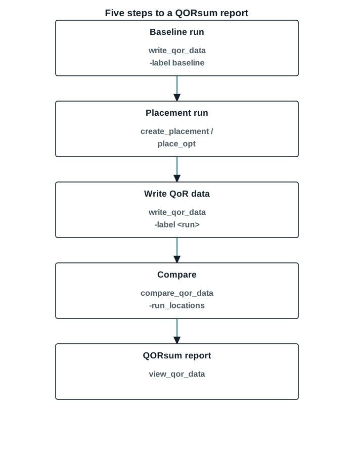
A single run's reports tell you whether that run is internally consistent. They do not tell you whether a change helped. For that, ICC2 generates a web-based QORsum report comparing captured QoR data across runs, through a fixed chain of commands.
- Configure capture (optional) —
set_qor_data_options: pick the leakage/dynamic power scenarios and clock/scenario used for summary rows, and optionally a run name. - Capture each run —
write_qor_data, once per flow stage you want recorded, each run labeled so it stays distinguishable (for exampleplace_opt,post_cts). - Generate the comparison —
compare_qor_data, pointing at each captured run's location, builds the QORsum report. - View —
view_qor_dataopens the generated report.
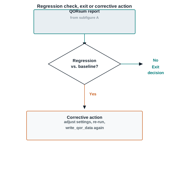
write_qor_data call rather than a generic restart.write_qor_data
Captures QoR results to disk for the QORsum web application.
- What it isRuns and captures a standard set of reports (
report_qor,report_power, and others) to a labeled stage directory. - Why you run itTo record a comparable snapshot at a specific flow stage — the only way
compare_qor_datahas something to compare. - When in flowOnce for the pre-placement baseline, and again after each placement/optimization run you want to compare.
- Command purposeCaptures QoR data (timing, power, runtime) to a stage directory that
compare_qor_datalater reads. Option names (label, output directory, report group) are release-specific — checkwrite_qor_data -help. - Check your release
icc2_shell> write_qor_data -label place_opt -output ./qor_data/run1 - What ICC2 changesWrites reports and QoR data tables to a stage directory, labeled per run so that runs stay distinguishable when compared later.
- What to read backNothing directly — its output is consumed by
compare_qor_data. - TrapAll runs you intend to compare together must use consistent, comparable output locations — a later
compare_qor_datacall finds all labeled stages under one run location and treats them as one ordered sequence. - If you skip itNo comparable record exists of this stage — only whatever individual reports you happened to run and save by hand.
| Command | Option | Behavior |
|---|---|---|
compare_qor_data | -force | Builds the QORsum report from one or more captured run locations; default output directory ./compare_qor_data; does not overwrite existing output unless -force is given; unnamed runs default to run1, run2, etc. The option names for pointing at run locations and naming runs are release-specific — check compare_qor_data -help. |
view_qor_data | release-specific | Opens the generated QORsum report, by default via a local web server. Option names for the report location, disabling the web server, or choosing a port are release-specific — check view_qor_data -help. |
Baseline, shading, and delta style
By default, the first row of data is the baseline run; all other runs are compared against it, and the baseline is highlighted to mark it as the golden result. A different baseline can be chosen from the Runs dialog. Non-baseline cells are shaded red for a degradation and green for an improvement relative to the baseline, with lighter shading for a smaller difference and darker shading for a larger one. Right-clicking the table cycles the display between raw values, a percentage delta against the baseline, and an absolute delta against the baseline (shown in italic). Columns can be sorted by clicking their header (ascending, then descending), and both the visible metrics and the visible runs can be filtered from their respective dialogs.
Nimbus‑8: comparing three placement runs
The single-run worked example earlier in this chapter shows one path through placement. In practice you often run more than one experiment and need to know which is actually better — not just which one has the best single number.
| Metric | Run 1 — baseline placement | Run 2 — timing-focused | Run 3 — congestion-focused |
|---|---|---|---|
| Worst setup slack | −0.09 ns | +0.04 ns | −0.14 ns |
| Total negative slack (TNS) | −3.8 ns | −2.1 ns | −5.6 ns |
| Failing endpoints | 41 | 26 | 58 |
| Peak routing congestion | High (2 hot spots) | Higher (3 hot spots) | Low (0 hot spots) |
| Total dynamic power | 612 mW | 648 mW | 601 mW |
| Core utilization | 79.4% | 79.4% | 79.4% |
| Runtime | 38 min | 52 min | 44 min |
Run 2 has the best worst-slack and the fewest failing endpoints — the number a quick glance would call "best." But it also introduced a new congestion hot spot and raised dynamic power, at a real runtime cost. Run 3 solved congestion cleanly but let timing degrade further. None of the three is unambiguously best; the QORsum comparison is what surfaces the tradeoff, instead of a single report_timing from Run 2 in isolation making it look like a clean win.
Adding and removing tie cells
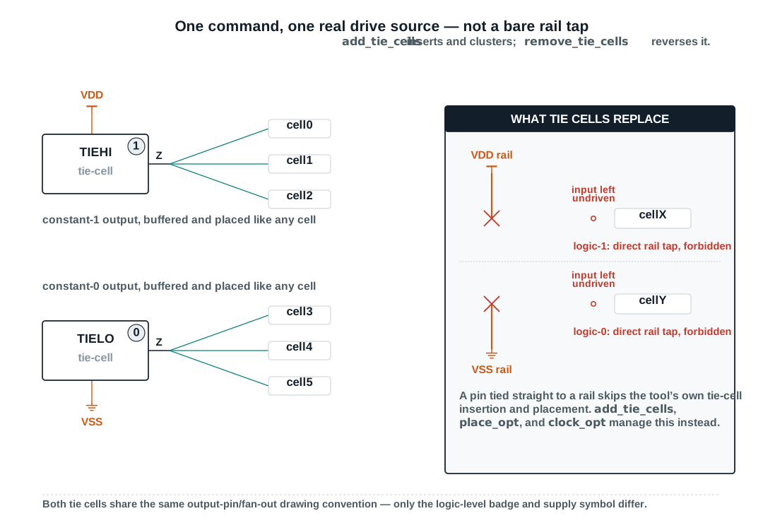
A constant logic-0 or logic-1 pin needs a real drive source, not a direct wire to a supply rail. A tie cell — a small library cell built to drive a fixed constant — provides that source. place_opt and clock_opt insert tie cells automatically wherever their own optimization creates a constant-driven pin; add_tie_cells and remove_tie_cells give you explicit, standalone control over the same operation.
add_tie_cells
Inserts tie cells to drive constant pins in the design.
- What it isFinds constant-driven pins (by default, every constant pin in the current design) and drives them with a usable tie-high or tie-low library cell.
- Why you run itTo explicitly check for, and fix, any constant pin left undriven after placement and optimization's automatic insertion.
- When in flowAfter the main
place_opt/optimization pass, as an explicit check before the exit gate — not a substitute for the automatic insertion during optimization. - Example
icc2_shell> add_tie_cells - Check your releaseCheck
add_tie_cells -helpon your release for a pin/object-scoping option and for cell-restriction options. - What ICC2 changesInserts tie-high or tie-low cell instances and connects them to constant pins, using only library cells that are not marked don't-use or don't-touch and are usable for optimization.
- What to read backRe-running
add_tie_cellswith no new insertions reported is itself the pass evidence; a placement-status or netlist check confirms the new tie-cell instances landed sensibly. - TrapIf no usable tie cell exists in the library (all candidates don't-use or don't-touch), a constant pin can be left undriven with no error — check the library's tie-cell availability, not just the command's return.
- If you skip itAny constant pin optimization did not already handle stays undriven, an open item most easily caught here rather than in a later stage's DRC.
remove_tie_cells
Removes tie cells from the current design.
- What it isThe inverse of
add_tie_cells: removes tie-cell instances, either a specific list or every tie cell in the design. - Why you run itTo undo a tie-cell insertion before retrying it with different library-cell constraints, or to clear tie cells before a structural change that would otherwise leave them stranded.
- When in flowRarely mid-chapter; a targeted cleanup step before re-running
add_tie_cellswith a different cell list. - Example
icc2_shell> remove_tie_cells - Check your releaseCheck
remove_tie_cells -helpon your release for a cell/library-cell scoping option. - What ICC2 changesWith no option, removes every tie cell in the design; a scoped removal targeting one cell or library cell may also be possible — verify the option name before scripting it.
- What to read backA subsequent
add_tie_cellsor netlist check confirming the constant pins that lost their driver are now handled the way you intend. - TrapRemoving every tie cell in the design with no option can leave every constant pin that depended on one undriven until
add_tie_cellsis run again — don't leave a design in that state at a checkpoint. - If you skip itNot applicable in the normal flow — this is a corrective command, not a required step.
Twenty-two settings that shape placement and legalization beyond the default flow
The worked example and command cards above cover the default place_opt/create_placement/legalize_placement path. The ICC2 User Guide documents a further set of application-option-driven controls — mostly under its "Specifying Placement Settings" and "Specifying Legalization Settings" topics — that shape how placement and legalization behave in specific situations: early-stage constraint uncertainty, clock-gating structure, congestion, wide cells and advanced nodes, dynamic power, and several legalization-quality features. Each entry below is scoped to a specific situation — it is not a general recommendation to enable all of them.
Consequences of inaccurate early placement constraints
- Purpose
- Let coarse placement continue, with a clear warning trail, when early-stage placement constraints (move bounds, blockages) turn out to be too tight for the cells that must go in them.
- Problem it solves
- Early in a design cycle, floorplan-stage move bounds and blockages are often drawn before final cell counts and cell sizes are known. If a bound ends up overutilized once real cells are placed, the tool can exit during coarse placement instead of finishing with a diagnosable result.
- When to use it
- Early design cycles where floorplan constraints are known to be provisional — not as a permanent substitute for fixing an undersized region.
- Prerequisites
A block that has already failed, or is expected to fail, coarse placement due to a specific overutilized move bound or blockage-covered region.
- ICC2 workflow
- Set
place.coarse.handle_early_datatotruebefore runningcreate_placement/place_opt. - Let placement continue into the overutilized region instead of exiting.
- Read the PLACE-089/PLACE-083/PLACE-084 warning messages the tool prints to locate exactly which move bound is overutilized and by how much.
- Optionally tune
place.coarse.utilization_warning_threshold(default triggers above 90% region utilization) to change when the warning fires.
- Set
- Commands and options
Commands and options for Consequences of inaccurate early placement constraints Command / option Behavior place.coarse.handle_early_dataapp option, default false — continues placement through overutilized/blockage-covered regions instead of exiting place.coarse.utilization_warning_thresholdapp option — utilization percentage (default 90%) above which PLACE-027-class warnings are issued - Expected reports or evidence
- PLACE-089 (“Utilization of move_bound_0 is 109%”), PLACE-083, and PLACE-084 warning messages in the placement log, naming the specific overutilized region.
- Risks and tradeoffs
- This is a diagnostic escape hatch, not a fix — an overutilized region it silently plows through still needs its move bound, blockage, or cell budget corrected before the block is real.
- Exit-checklist implication
- A block that needed
handle_early_datato finish coarse placement is not exit-gate clean until the underlying region-sizing problem the PLACE-089 warning named has been corrected and re-run without the warning.
Automatic group bounds for clock-gating structures
- Purpose
- Automatically keep an integrated clock-gating (ICG) cell and the sequential cells it drives close together during placement, without hand-authoring a group bound for every clock-gating fanout.
- Problem it solves
- An ICG cell placed far from the registers it gates lengthens the enable and clock paths it drives, working against both timing and the clock tree that CTS will build later.
- When to use it
- Any block using integrated clock gating where you have not already defined manual group bounds for the ICG/sequential-cell clusters.
- Prerequisites
Clock-gating cells already merged (
merge_clock_gates, or the equivalent automatic merge duringplace_opt'sinitial_place/initial_optstage).- ICC2 workflow
- Set
place.coarse.icg_auto_boundtotruebefore coarse placement. - The tool creates automatic group bounds at the start of placement and removes them at the end — cells already in another group bound are excluded.
- Optionally cap fanout per automatic bound with
place.coarse.icg_auto_bound_fanout_limit(default 40).
- Set
- Commands and options
Commands and options for Automatic group bounds for clock-gating structures Command / option Behavior place.coarse.icg_auto_boundapp option, default false — enables automatic group-bound generation for ICG cells and their driven sequential cells place.coarse.icg_auto_bound_fanout_limitapp option, default 40 — caps how many fanout cells an automatic bound can include - Expected reports or evidence
- There is no dedicated report for this feature. Check its effect indirectly via placement proximity of ICG cells to their driven registers (for example a cell-density or congestion map) and via the resulting group-bound set from
report_bounds, since it is removed again at the end of placement. - Risks and tradeoffs
- An automatic bound only exists during placement itself; it is not a persistent design constraint, so it cannot be inspected after placement completes the way a manually defined group bound can.
- Exit-checklist implication
- Not a standalone gate item; feeds into the general clock-gating-optimization and congestion checks already on the setup/exit gates.
Placement density control
- Purpose
- Cap how densely the tool packs cells in a region, either uniformly or specifically to relieve congestion around already-congested areas.
- Problem it solves
- Left uncontrolled, coarse placement can pack cells tightly enough to leave no routing headroom, or can pack the area surrounding a congested hot spot just as tightly as the hot spot itself, leaving nowhere to spread cells out of it.
- When to use it
- Whenever a block needs an explicit density ceiling instead of the tool's own auto-derived schedule — commonly once a first placement pass shows congestion or over-tight legalization.
- Prerequisites
A baseline utilization figure for the block, so the chosen density/utilization value is meaningfully between 1 and that utilization.
- ICC2 workflow
- Choose a value between 1 and the block's overall utilization.
- Set
place.coarse.max_densityfor an overall density ceiling, and/orplace.coarse.congestion_driven_max_utilto control density specifically in the region surrounding congestion hot spots. - Leave
place.coarse.auto_density_control(default-enhanced) enabled unless you have a specific reason to disable it — explicit values you set always take precedence over the tool's derived ones regardless of this setting. - Read the PLACE-027 info messages during placement to see which density/utilization values the tool actually used.
- Commands and options
Commands and options for Placement density control Command / option Behavior place.coarse.max_densityapp option — maximum density ceiling for non-congestion-driven placement; 0 forces uniform spreading place.coarse.congestion_driven_max_utilapp option, default 0.93 — max utilization in areas surrounding congestion hot spots place.coarse.auto_density_controlapp option, default -enhanced — tool-derived density schedule when explicit values are not set - Expected reports or evidence
- PLACE-027 info message (“Automatic density control has selected the following settings: max_density 0.60, congestion_driven_max_util 0.77”) printed during placement.
- Risks and tradeoffs
- Density/utilization limits apply independently per placeable area (voltage area, exclusive move bound) rather than as a block-wide average — a single global number does not describe every region's actual headroom.
- Exit-checklist implication
- Feeds the setup-gate's density/congestion checks; a block still showing PLACE-027 values far from what was intended should be revisited before sign-off.
Congestion-driven restructuring
- Purpose
- Restructure logic during coarse placement specifically to reduce routing congestion, with tunable effort and a guard against uncontrolled logic-depth growth.
- Problem it solves
- Congestion is sometimes a structural problem, not just a placement problem — the netlist's fan-in/fan-out shape itself creates local wiring demand that spreading cells alone cannot fix.
- When to use it
- Congested blocks where
create_placement(without-timing_driven) or theplace_optinitial_placestage's default restructuring is not aggressive enough, or is adding too much logic depth. - Prerequisites
A congestion signature already visible from a first coarse-placement pass or congestion map.
- ICC2 workflow
- By default this restructuring already runs during
create_placement(unless-timing_drivenis set) and duringplace_opt'sinitial_placestage. - Raise or lower effort with
place.coarse.cong_restruct_effort(low/medium/high/ultra; default medium). - If restructuring is adding too many logic levels to critical paths, cap it with
place.coarse.cong_restruct_depth_awareset totrue(limits added depth to at most three levels).
- By default this restructuring already runs during
- Commands and options
Commands and options for Congestion-driven restructuring Command / option Behavior place.coarse.cong_restruct_effortapp option, default medium — low/medium/high/ultra effort for congestion-driven restructuring place.coarse.cong_restruct_depth_awareapp option, default false — caps added path depth from restructuring to 3 levels of logic - Expected reports or evidence
- Before/after congestion maps or
report_congestion-class evidence around the restructured region; a path-depth comparison ifcong_restruct_depth_awarewas enabled specifically to bound depth growth. - Risks and tradeoffs
- Restructuring changes logic structure, not just placement — at higher effort it can add path depth that partially offsets its own congestion win with a timing cost, which is exactly what
cong_restruct_depth_awareexists to bound. - Exit-checklist implication
- Supports the congestion items on the placement-analysis sequence and exit gate; not a separate gate item on its own.
Wide-cell density handling
- Purpose
- Keep wide standard cells placeable and legalizable without large displacement, on advanced nodes where a wide cell may only fit in one position between vertical power straps.
- Problem it solves
- If a cell cannot straddle the vertical power straps and its width exceeds half the strap pitch, only one such cell fits between a given pair of straps — packing too many wide cells into the same strap-bounded region makes them impossible to legalize without moving them a long way.
- When to use it
- Advanced technology nodes with meaningful vertical power-strap pitch constraints and a noticeable population of wide cells (wide multiplexers, wide drive-strength buffers, and similar).
- Prerequisites
None beyond being on a node where this strap/cell-width interaction applies; the tool does not need extra setup data beyond the technology file's strap geometry.
- ICC2 workflow
- Set
place.coarse.wide_cell_use_modeltotruebefore coarse placement. - The tool then minimizes the density of these wide cells during placement so legalization does not have to displace them far afterward.
- Set
- Commands and options
Commands and options for Wide-cell density handling Command / option Behavior place.coarse.wide_cell_use_modelapp option, default false — enables wide-cell-aware density modeling during coarse placement - Expected reports or evidence
- Legalization RMS-displacement figures for wide-cell instances specifically, compared with and without the option enabled.
- Risks and tradeoffs
- Only relevant where the strap-pitch/cell-width interaction actually applies; enabling it on a design without meaningfully wide cells has nothing to improve.
- Exit-checklist implication
- Feeds the legalization-displacement checks on the exit gate for designs where wide cells are a known population.
Cell-pin effects on placement
- Purpose
- Make coarse placement aware of pin-access cost or local pin density up front, instead of discovering pin-access DRC problems only after legalization or routing.
- Problem it solves
- Dense clusters of hard-to-access pins can produce routing and legalization difficulty that generic cell-area-based placement has no way to anticipate.
- When to use it
- Technology nodes of 7, 7+, 5, s5, or s4 (technology-specific pin-cost model available) or any other node needing generic pin-density awareness.
- Prerequisites
set_technology -nodealready set for the block, since the choice of model depends on it.- ICC2 workflow
- On 7/7+/5/s5/s4 nodes: set
place.coarse.pin_cost_awaretotruefor the technology-specific pin-cost model (this takes priority over pin-density awareness on these nodes). - On any node: set
place.coarse.pin_density_awaretotrueto control maximum local pin density instead. - Both default to
false; on 7/7+/5/s5/s4 nodespin_cost_aware=truewins regardless ofpin_density_aware; on other nodes onlypin_density_awarehas effect.
- On 7/7+/5/s5/s4 nodes: set
- Commands and options
Commands and options for Cell-pin effects on placement Command / option Behavior place.coarse.pin_cost_awareapp option, default false — technology-specific pin-cost-aware placement (7/7+/5/s5/s4 nodes only) place.coarse.pin_density_awareapp option, default false — generic maximum-local-pin-density-aware placement - Expected reports or evidence
- Pin-access DRC counts, or the pin-density map from
#visual-inspection, before and after enabling the relevant option. - Risks and tradeoffs
- Setting both options without checking Table 7's precedence rule on 7/7+/5/s5/s4 nodes can leave an engineer believing pin-density awareness is active when the pin-cost model has actually taken over.
- Exit-checklist implication
- Feeds pin-access DRC and legalization-displacement checks on the exit gate.
Effects of nondefault-rule clock nets
- Purpose
- Account, during placement, for the extra routing space that nondefault routing rules (NDR) on clock nets will need later, instead of discovering the resulting congestion only after clock routing.
- Problem it solves
- Nondefault routing rules are used extensively on clock nets to improve timing and reduce crosstalk, but they need more space than default-rule routing — congestion from this can appear only after clock routing if placement never accounted for it.
- When to use it
- Blocks with clock nets known to use nondefault routing rules, especially where post-clock-routing congestion has been a problem before.
- Prerequisites
Clock definitions and the intended nondefault routing rule assignments already established (the setup-gate's constraints/clocks row).
- ICC2 workflow
- Set
place.coarse.ndr_area_awaretotruebefore coarse placement. - The tool factors the anticipated NDR routing-space demand of clock nets into its congestion accounting during placement.
- Set
- Commands and options
Commands and options for Effects of nondefault-rule clock nets Command / option Behavior place.coarse.ndr_area_awareapp option, default false — accounts for nondefault-routing-rule clock-net congestion during coarse placement - Expected reports or evidence
- Post-clock-routing congestion comparison (with vs. without the option) in the regions the NDR clock nets pass through.
- Risks and tradeoffs
- Only helps congestion that is actually attributable to NDR clock-net routing; does not address unrelated congestion sources.
- Exit-checklist implication
- Feeds the congestion items on the placement-analysis sequence and exit gate for designs using NDR clock nets.
Clock-gating cells associated with sequential arrays
- Purpose
- Reduce clock-net congestion specifically around sequential arrays (register files and similar row/column register structures) by making placement aware of the single clock-gating cell that typically drives a whole row.
- Problem it solves
- A sequential array is a group of registers arranged as a two-dimensional array, usually with the clock pins along one row driven by a single clock-gating cell; naive placement of that structure can create local clock-net congestion.
- When to use it
- Blocks containing register-file-like sequential arrays with row-shared clock gating.
- Prerequisites
None beyond the sequential array existing in the netlist in a form the tool can recognize as such.
- ICC2 workflow
- Set
place.coarse.seq_array_icg_awaretotruebefore coarse placement. - The tool places the array's clock-gating cell and the row it drives with awareness of this shared-driver structure, reducing the clock-net congestion it would otherwise cause.
- Set
- Commands and options
Commands and options for Clock-gating cells associated with sequential arrays Command / option Behavior place.coarse.seq_array_icg_awareapp option, default false — reduces clock-net congestion caused by sequential-array clock gating - Expected reports or evidence
- Local congestion map around the sequential array before/after enabling the option.
- Risks and tradeoffs
- Specific to arrays with a single shared clock-gating driver per row; does not apply to arrays clocked with per-register gating.
- Exit-checklist implication
- Feeds the congestion checks on the exit gate for designs containing register-file-style sequential arrays.
Legalization effects during placement
- Purpose
- Make coarse placement aware, ahead of time, of the legalization limits and restrictions a cell will face — for example a wide cell that cannot legally sit at a specific location because of a power-strap position — so fewer cells need large displacements during legalization itself.
- Problem it solves
- Coarse placement that ignores legalization restrictions can place a cell somewhere it can never legally be, forcing a large corrective move once legalization runs.
- When to use it
- Blocks reporting many cells with small-to-medium legalization displacements — that is the use case this feature targets.
- Prerequisites
A baseline legalization RMS-displacement measurement to compare against.
- ICC2 workflow
- Set
place.coarse.enhanced_legalizer_driven_placementtotruebefore coarse placement. - Re-run legalization and compare RMS displacement values against the baseline to confirm the option is actually reducing displacement for this design.
- Set
- Commands and options
Commands and options for Legalization effects during placement Command / option Behavior place.coarse.enhanced_legalizer_driven_placementapp option, default false — makes coarse placement aware of legalization limits/restrictions - Expected reports or evidence
- RMS displacement values reported during
legalize_placement, compared before/after enabling the option — that comparison is the check. - Risks and tradeoffs
- The benefit is scoped to designs with many small-to-medium displacements; it is not a fix for a design with a few very large, structural placement problems.
- Exit-checklist implication
- Directly supports the legalization-displacement checks on the exit gate.
Dynamic-power QoR during placement
- Purpose
- Improve the dynamic-power QoR of a placement without degrading its timing QoR, by making the coarse placer aware of switching-activity-driven power alongside timing.
- Problem it solves
- Placement decisions made purely for timing or area can leave dynamic power unoptimized, even though placement-stage locality (net length, cell selection proximity) has real influence over switching power.
- When to use it
- Designs with a defined power budget or dynamic-power target, once switching activity has been annotated.
- Prerequisites
- Switching activity annotated on the design (see the Analyzing Power annotation workflow).
- At least one scenario enabled for dynamic-power optimization via
set_scenario_status -dynamic_power true.
- ICC2 workflow
- Annotate switching activity on the design.
- Enable dynamic-power optimization on at least one scenario:
set_scenario_status -dynamic_power true. - Enable dynamic-power-driven placement for
create_placement,refine_placement,place_opt, orclock_optby settingplace.coarse.enhanced_low_power_efforttonone/low/medium/high(default low).
- Commands and options
Commands and options for Dynamic-power QoR during placement Command / option Behavior set_scenario_status -dynamic_power truecommand option — enables a scenario for dynamic-power optimization (prerequisite) place.coarse.enhanced_low_power_effortapp option, default low — none/low/medium/high effort for dynamic-power-driven placement - Expected reports or evidence
- Dynamic/switching power from
report_powerbefore/after, alongside a timing check that timing QoR held — this feature targets power without affecting timing QoR. - Risks and tradeoffs
- Requires switching activity to already be annotated and a dynamic-power scenario enabled; without both prerequisites the effort-level setting alone has nothing to optimize against.
- Exit-checklist implication
- Feeds the power-QoR checks in Analyzing Power and the exit gate.
Repeater spreading
- Purpose
- Reduce congestion caused by chains of repeater cells (buffers, inverters, or pipelined registers) clumping along the edges or corners of macros or blockages, by spreading them in an orthogonal direction.
- Problem it solves
- Repeater chains naturally tend to run along macro/blockage edges and corners; left unspread, that clumping is itself a congestion source.
- When to use it
- Blocks with macros or large blockages and repeater-chain-heavy paths running along their boundaries, especially where congestion maps show hot spots hugging those edges.
- Prerequisites
None beyond the block having macros/blockages with repeater chains routed along them.
- ICC2 workflow
- Set
place.coarse.spread_repeater_pathstotruebefore runningcreate_placement,place_opt, orclock_opt. - The tool spreads the repeater cells in an orthogonal direction to reduce the edge/corner clumping.
- Set
- Commands and options
Commands and options for Repeater spreading Command / option Behavior place.coarse.spread_repeater_pathsapp option, default false — spreads repeater chains along macro/blockage edges and corners to reduce congestion - Expected reports or evidence
- Congestion map comparison specifically along macro/blockage boundaries, before/after enabling the option.
- Risks and tradeoffs
- Targets a specific congestion pattern (edge/corner repeater clumping); does not address congestion from other causes.
- Exit-checklist implication
- Feeds the congestion items on the placement-analysis sequence and exit gate.
Limiting large cell displacement
- Purpose
- Reduce how far legalization has to move individual cells, using orientation flexibility and a many-small-moves strategy instead of moving any single cell a long distance.
- Problem it solves
- Legalization that only knows how to push one violating cell directly to its nearest legal site can end up moving that cell a long way, degrading the placement's original QoR-driven positions.
- When to use it
- Blocks where legalization is reporting large per-cell displacement, particularly designs where cell orientation is not already fixed by other constraints.
- Prerequisites
None beyond having a legalization displacement problem to address.
- ICC2 workflow
- Enable orientation optimization:
place.legalize.optimize_orientationstotrue— lets the tool consider flipping cell orientations to reduce displacement. - Enable stream placement:
place.legalize.stream_placetotrue— moves many cells a small distance rather than one cell a large distance. - Tune stream placement further with
place.legalize.stream_effortandplace.legalize.stream_effort_limitif needed.
- Enable orientation optimization:
- Commands and options
Commands and options for Limiting large cell displacement Command / option Behavior place.legalize.optimize_orientationsapp option, default false — allows orientation flips during legalization to reduce displacement place.legalize.stream_placeapp option, default false — distributes displacement across many small cell moves place.legalize.stream_effort / stream_effort_limitapp options — further control stream-placement effort - Expected reports or evidence
- RMS/maximum displacement values from
legalize_placement, before/after enabling these options. - Risks and tradeoffs
- Stream placement trades a single large move for many small ones — still real movement, so it should be checked against timing-critical nets it might have nudged, not assumed free.
- Exit-checklist implication
- Directly supports the legalization-displacement checks on the exit gate.
Pin-access-aware legalization
- Purpose
- Improve routability in high-pin-density areas by redistributing cells during legalization on advanced technology nodes.
- Problem it solves
- Advanced-node designs can legalize into cell arrangements that are legally valid but leave local pin density too high for the routing stage to access cleanly.
- When to use it
- Advanced technology nodes, particularly where pin-access DRC or routability problems have shown up after legalization in earlier runs.
- Prerequisites
None beyond being on an advanced node where pin-access-driven redistribution is meaningful.
- ICC2 workflow
- Set
place.legalize.optimize_pin_access_using_cell_spacingtotruebefore legalization. - The tool redistributes cells in high-pin-density areas during legalization to improve routability.
- Set
- Commands and options
Commands and options for Pin-access-aware legalization Command / option Behavior place.legalize.optimize_pin_access_using_cell_spacingapp option, default false — enables pin-access-driven cell redistribution during legalization - Expected reports or evidence
- Pin-access DRC counts, or a pin-density map, before/after enabling the option.
- Risks and tradeoffs
- Targeted at advanced technology nodes specifically; it is not generally applicable to all node classes.
- Exit-checklist implication
- Feeds the pin-access DRC checks on the exit gate.
Concurrent legalization and detailed routing (CLDR)
- Purpose
- Improve DRC convergence on pin-access violations after route optimization (RO) or hierarchical route optimization (HRO), by integrating legalization more tightly with detailed routing.
- Problem it solves
- Pin-access DRC violations found after RO/HRO can be slow to converge when legalization and detailed routing are treated as fully separate passes.
- When to use it
- Designs seeing persistent pin-access DRC after RO/HRO that ordinary legalize-then-route iteration is not converging quickly.
- Prerequisites
A design that has already been through, or is about to go through, RO or HRO.
- ICC2 workflow
- Set
place.legalize.enable_cldrtotrue:set_app_options -name place.legalize.enable_cldr -value true
- Run the normal RO/HRO flow; CLDR integration improves DRC convergence on pin-access issues as part of it.
- Set
- Commands and options
Commands and options for Concurrent legalization and detailed routing (CLDR) Command / option Behavior place.legalize.enable_cldrapp option, default false — enables Concurrent Legalize and Detail Route integration for pin-access DRC convergence - Expected reports or evidence
- Pin-access DRC violation count after RO/HRO, before/after enabling CLDR.
- Risks and tradeoffs
- Named specifically as a DRC convergence aid after RO or HRO — not a general-purpose legalization mode for earlier flow stages.
- Exit-checklist implication
- Feeds the DRC-convergence and pin-access items on the exit gate.
Advanced power-ground checks relevant to placement
- Purpose
- Enable stricter physical DRC checking between cells and prerouted power/ground (PG) net shapes on advanced technology nodes, including checks across multiple neighboring cells at once.
- Problem it solves
- At 12nm, 7nm, and smaller nodes, cell-to-prerouted-PG-net interactions can create DRC violations that simpler, single-cell-at-a-time checking misses, especially where several cells and PG shapes interact near a boundary.
- When to use it
- Advanced technology nodes (12nm and below), especially where PG-related DRC has appeared after legalization on prior runs.
- Prerequisites
None beyond being on a node where this checking is relevant; multi-cell checks build on the basic advanced PG check being enabled first.
- ICC2 workflow
- Enable the base check:
place.legalize.enable_advanced_prerouted_net_checktotrue. - Optionally tune the accessibility checks with
place.legalize.advanced_layer_access_checkandplace.legalize.advanced_libpin_access_check(default behavior suits most designs). - For simultaneous multi-cell PG checking, also set
place.legalize.enable_multi_cell_pnet_checkstotrue. - For multi-cell pin-access and track-capacity checks specifically at the last
route_optrun or afterroute_auto, additionally enableplace.legalize.enable_multi_cell_access_checkand, if needed,place.legalize.enable_multi_cell_track_capacity_check(the latter requires the former).
- Enable the base check:
- Commands and options
Commands and options for Advanced power-ground checks relevant to placement Command / option Behavior place.legalize.enable_advanced_prerouted_net_checkapp option, default false — advanced physical DRC between cells and prerouted PG nets (advanced nodes) place.legalize.enable_multi_cell_pnet_checksapp option, default false — simultaneous DRC checks across multiple cells and PG net shapes place.legalize.enable_multi_cell_access_checkapp option, default false — pin-access impact from neighboring cells/prerouted PG shapes place.legalize.enable_multi_cell_track_capacity_checkapp option, default false — track-capacity sufficiency check; requires enable_multi_cell_access_check- Expected reports or evidence
- PG-related DRC violation counts from legality checking (
check_legality) before/after enabling these checks. - Risks and tradeoffs
- Layered options with dependencies (track-capacity check requires the access check); enabling one without the other it depends on has no effect.
- Exit-checklist implication
- Feeds PG-DRC and legalization-cleanliness checks on the exit gate for advanced-node designs.
Advanced legalization algorithms
- Purpose
- Use 2D rule checking and cell-interaction-aware legalization algorithms, which reduce legalization runtime and support pin-access-optimizing strategies not available in the standard legalizer.
- Problem it solves
- Standard legalization can be slower and less able to account for cell-to-cell pin-access interaction than a 2D-rule-aware algorithm on advanced nodes.
- When to use it
- Advanced-node blocks where legalization runtime or pin-access-aware legalization quality is a concern; a prerequisite for variant-aware legalization's fullest behavior.
- Prerequisites
Awareness that the
legalize_placementcommand's-cellsoption is not supported once the advanced legalizer is enabled.- ICC2 workflow
- Enable the algorithm:
place.legalize.enable_advanced_legalizertotrue. - Optionally specify undetected additional rules with
place.legalize.enable_advanced_legalizer_rules. - Choose pin-access optimization strategy with
place.legalize.optimize_pin_access_strategies:horizontal_align,avoid_high_pin_density, or both together. - For runtime, optionally enable multithreading:
place.legalize.enable_threaded_advanced_legalizertotrue, then configure multithreading as described for the tool generally. - For multithreaded legality checking specifically, enable the advanced legalizer, configure multithreading, then run
check_legality.
- Enable the algorithm:
- Commands and options
Commands and options for Advanced legalization algorithms Command / option Behavior place.legalize.enable_advanced_legalizerapp option, default false — enables 2D-rule-aware advanced legalization algorithms place.legalize.optimize_pin_access_strategiesapp option — horizontal_alignand/oravoid_high_pin_densitypin-access optimization strategiesplace.legalize.enable_threaded_advanced_legalizerapp option, default false — multithreaded advanced legalization check_legalitycommand — legality checking, can run multithreaded once the advanced legalizer and multithreading are configured - Expected reports or evidence
- Legalization runtime comparison, and
check_legalityoutput, before/after enabling the advanced legalizer. - Risks and tradeoffs
- The
-cellsoption oflegalize_placementstops working once the advanced legalizer is enabled — a targeted, cell-list legalization workflow built on that option needs to be re-checked. - Exit-checklist implication
- Feeds the legalization-cleanliness and runtime items on the exit gate for advanced-node designs.
Variant-aware legalization
- Purpose
- Legalize a cell by swapping it for a functionally equivalent variant with different pin placement or pin color, instead of physically moving it, when a library provides such variants.
- Problem it solves
- A library can offer functionally identical cells whose pins sit in different locations or on different mask colors; ordinary legalization has no way to use that equivalence and can only move the cell.
- When to use it
- Libraries that are variant-ready (define
physical_variant_cellsin their Liberty source) or can be made variant-ready via the Library Manager tool. - Prerequisites
- A variant-ready compiled library, or equivalent cell groups defined via
create_cell_groupsin the Library Manager tool (lm_shell). report_cell_groupscan confirm equivalent cell groups exist in either the Library Manager or IC Compiler II tool.
- A variant-ready compiled library, or equivalent cell groups defined via
- ICC2 workflow
- If the logic library is not already variant-ready, define equivalent cell groups in the Library Manager tool:
create_workspace,create_cell_groupper group,check_workspace,commit_workspace. - Enable variant-aware legalization:
place.legalize.enable_variant_awaretotrue. - For pin-track/pin-color alignment specifically, also enable
place.legalize.enable_prerouted_net_checkandplace.legalize.enable_pin_color_alignment_check, and specify the layers to align viaplace.legalize.pin_color_alignment_layers.
- If the logic library is not already variant-ready, define equivalent cell groups in the Library Manager tool:
- Commands and options
Commands and options for Variant-aware legalization Command / option Behavior place.legalize.enable_variant_awareapp option, default false — enables variant-aware legalization create_cell_group (lm_shell)command — defines equivalent cell groups when the library is not already variant-ready place.legalize.enable_pin_color_alignment_checkapp option — pin-color-aware alignment during variant-aware legalization place.legalize.pin_color_alignment_layersapp option — layers to align for pin-color checking - Expected reports or evidence
report_cell_groupsconfirming equivalent cell groups are recognized; legalization DRC-violation count before/after, showing violations fixed by variant substitution instead of displacement.- Risks and tradeoffs
- If a violating cell has no variant, the tool falls back to moving it — variant-aware legalization reduces displacement, it does not eliminate the need for legalization movement entirely.
- Exit-checklist implication
- Supports legalization-displacement and DRC-cleanliness checks on the exit gate for libraries that offer variants.
Cell legal-placeability analysis
- Purpose
- Check, after placement and legalization constraints are fully specified, whether specific library cells can actually be legally placed anywhere in the block (or a chosen region) — before relying on them in the design.
- Problem it solves
- A library cell can be structurally legal in isolation but practically unplaceable in a given block's power-strap/track geometry, something that is easy to discover too late without a dedicated check.
- When to use it
- After all placement and legalization constraints and settings are specified, particularly for cells you suspect may be hard to legalize (wide cells, cells with unusual pin geometry).
- Prerequisites
Placement and legalization constraints/settings already finalized for the block, since the analysis checks against them.
- ICC2 workflow
- Run
analyze_lib_cell_placement -lib_cellsnaming the cells of interest. - Optionally scope the search to a region with
-region(default: entire core area). - Optionally limit the number of sites checked with
-trials.
- Run
- Commands and options
Commands and options for Cell legal-placeability analysis Command / option Behavior analyze_lib_cell_placement -lib_cellscommand — checks whether named library cells can be legally placed; -region and -trials scope the search - Expected reports or evidence
- The pass/fail-per-cell result of
analyze_lib_cell_placement, run against the cells and region of concern. - Risks and tradeoffs
- A cell that fails this analysis for the whole core area may still be usable if legally placeable only in a subregion — read the
-region-scoped results before excluding a cell outright. - Exit-checklist implication
- A useful pre-flight check to run before committing a design to a library cell that later legalization runs might reject outright.
Placement-stage parasitic estimation
- Purpose
- Improve correlation between preroute (placement/optimization-stage) timing and the eventual postroute result, by using more realistic per-net parasitic estimation during
place_opt/clock_optinstead of a purely model-based estimate. - Problem it solves
- A purely model-based preroute parasitic estimate can diverge meaningfully from what routing eventually produces, especially where per-unit resistance varies across routing layers or on advanced nodes.
- When to use it
- Designs where preroute-to-postroute timing correlation has historically been poor, or that use advanced technology nodes below 16nm (route-driven estimation is enabled there by default).
- Prerequisites
None beyond running
place_opt/clock_optnormally; global routing is performed internally as part of these features.- ICC2 workflow
- Global-route-layer-based (GRLB) estimation: set
opt.common.use_route_aware_estimationtoauto(enabled only where per-layer resistance varies) ortrue(always enabled). Remove it withremove_route_aware_estimationbefore routing. - Route-driven estimation (RDE): set
opt.common.enable_rdetotrue(default-on below 16nm already). When enabled, RDE runs during thefinal_optstage and overrides/ignores the GRLB setting; honors the-early_cap_scale/-late_cap_scale/-early_res_scale/-late_res_scaleoptions ofset_extraction_options. - If RDE is enabled, keep it enabled through all subsequent preroute optimization steps in the flow for consistency.
- Global-route-layer-based (GRLB) estimation: set
- Commands and options
Commands and options for Placement-stage parasitic estimation Command / option Behavior opt.common.use_route_aware_estimationapp option, default false — auto/true enables GRLB per-unit-resistance-aware RC estimation remove_route_aware_estimationcommand — removes global-route-based estimation before routing opt.common.enable_rdeapp option, default true below 16nm — enables route-driven parasitic estimation during final_opt - Expected reports or evidence
- Preroute-vs-postroute timing correlation (slack delta on the same paths) before/after enabling GRLB or RDE.
- Risks and tradeoffs
- RDE silently overrides/ignores the GRLB setting when both are enabled — do not assume both are contributing independently; and RDE should be kept on through the rest of the preroute flow once enabled, not toggled per-stage.
- Exit-checklist implication
- Supports the timing-correlation confidence behind the exit gate's timing checks, though it is a correlation aid, not a checklist item itself.
Area recovery in high-utilization designs
- Purpose
- Let a design that cannot legalize because of local high-utilization areas recover area in those regions during
place_opt/clock_opt, at a documented timing-QoR cost. - Problem it solves
- A region with utilization too high to legalize needs area freed up before legalization can succeed there, but ordinary optimization has no built-in mechanism scoped specifically to high-utilization small regions.
- When to use it
- Designs that are failing to legalize specifically because of small regions of high utilization — not a general-purpose area-reduction switch.
- Prerequisites
A confirmed legalization failure attributable to a high-utilization region, so the timing-QoR tradeoff is justified.
- ICC2 workflow
- Set
opt.common.small_region_area_recoverytotrue. - Run
place_optorclock_opt; area recovery happens during these commands in the high-utilization regions. - Re-check timing QoR afterward — this feature carries a timing-QoR cost.
- Set
- Commands and options
Commands and options for Area recovery in high-utilization designs Command / option Behavior opt.common.small_region_area_recoveryapp option, default false — performs area recovery in high-utilization regions during place_opt/clock_opt - Expected reports or evidence
- Legalization success/failure in the previously high-utilization region, plus a timing-QoR comparison (worst slack, TNS) before/after, since a degradation is expected.
- Risks and tradeoffs
- This slightly degrades timing QoR — use it as a targeted fix for a legalization blocker, not as a routine setting.
- Exit-checklist implication
- A design that needed this option to legalize should have that fact and its timing-QoR impact recorded before sign-off, not silently left enabled.
Advanced logic restructuring
- Purpose
- Restructure logic during the
final_optostage ofplace_opt/clock_opt, targeted at whichever combination of area, timing, and power QoR the design most needs to improve. - Problem it solves
- Standard optimization may leave area, timing, or power QoR short of target even after placement is legal and DRC-clean; targeted restructuring at the final optimization stage can recover some of that gap.
- When to use it
- Designs where
final_opto-stage QoR (area, timing, and/or power) needs a further push, and the specific metric(s) to prioritize are known. - Prerequisites
A clear sense of which QoR metric(s) matter most for this run, since the mode setting is a direct tradeoff choice, not a free win across all three.
- ICC2 workflow
- Set
opt.common.advanced_logic_restructuring_modeto the mode matching your priority:none(default, off),area,timing,power,area_timing,timing_power,area_power, orarea_timing_power. - Run
place_optorclock_opt; restructuring applies during thefinal_optostage.
- Set
- Commands and options
Commands and options for Advanced logic restructuring Command / option Behavior opt.common.advanced_logic_restructuring_modeapp option, default none — area/timing/power/area_timing/timing_power/area_power/area_timing_power restructuring targets for final_opto - Expected reports or evidence
report_qorcomparison (area, worst slack/TNS, power) before/after, for the specific metric(s) the chosen mode targets.- Risks and tradeoffs
- A mode that combines multiple targets (for example
area_timing_power) spreads restructuring effort across all three rather than maximizing any one — choose the narrowest mode that matches the actual priority. - Exit-checklist implication
- Feeds the QoR-comparison workflow in Comparing QoR Data; a mode other than the default should be recorded as a deliberate QoR-tradeoff choice.
Multibit retention registers
- Purpose
- Extend multibit register banking to retention registers used in power-gated (multivoltage/UPF) designs, combining single-bit retention registers into a multibit retention register where the library and retention strategy support it.
- Problem it solves
- Retention registers have retention-specific requirements (a shared retention strategy, matching retention-pin drivers, a matching multibit retention library cell) that ordinary multibit banking does not check for, so a naive banking pass can either miss legitimate retention-register banking opportunities or bank them incorrectly.
- When to use it
- Multivoltage/UPF designs using single-bit retention registers where the library offers a matching multibit retention cell.
- Prerequisites
- The single-bit retention registers share the same retention strategy and the same retention-pin driver.
- The cell library has a matching multibit retention register.
- The multibit retention library cell is registered for the retention strategy via
map_retention_cell -lib_cells.
- ICC2 workflow
- Confirm the four banking prerequisites above are met for the candidate registers.
- Identify multibit retention registers with
identify_multibit -register(not-mv_cell, for this specific case). - Bank as part of the normal multibit banking flow (see Performing Multibit Register Optimization).
- To split a previously banked multibit retention register back to single-bit cells, the library must have matching single-bit retention registers also registered via
map_retention_cell -lib_cells.
- Commands and options
Commands and options for Multibit retention registers Command / option Behavior identify_multibit -registercommand option — identifies multibit retention registers specifically (use -register, not -mv_cell, for this case) map_retention_cell -lib_cellscommand — registers a library cell (single-bit or multibit) as usable for a given retention strategy - Expected reports or evidence
- Post-banking netlist check confirming retention registers banked into the expected multibit retention cell, and that the retention strategy/UPF checks still pass.
- Risks and tradeoffs
- Skipping the
-registeroption (using-mv_cellinstead) is the wrong option for this case — check the exact option used in any banking script that touches retention registers. - Exit-checklist implication
- Extends the multibit-banking sequencing already on the exit gate; a multivoltage design with retention registers should confirm this path explicitly rather than assuming ordinary multibit banking covered them.
When something is wrong, start here
| Symptom | Likely cause | Where to look first |
|---|---|---|
A congestion hot spot persists after a full place_opt pass | Congestion-driven placement was never enabled, or its effort level was too low for this design | -congestion and -congestion_effort on create_placement, or a targeted refine_placement -congestion_effort high pass |
| Placement QoR shows unexpectedly long total wire length | Timing-driven placement was never enabled, so the placer optimized for area and legality alone | -timing_driven or -buffering_aware_timing_driven on create_placement |
| IR-drop-aware placement appears to have done nothing | The application option was set after final_place already ran, so the rerun step was skipped or misordered | Sequence: place_opt -to final_place, then set the option, then place_opt -from final_place |
| Multibit banking did not reduce the clock tree's buffer count as expected | Registers driven by equivalent, but not identical, clock-gating cells were not considered for banking | multibit.banking.across_equivalent_icg application option |
A cell near a macro will not move during refine_placement | The cell's placement status is fixed or locked, intentionally or by accident | get_attribute for the cell's status, then set_placement_status if the lock was unintended |
| A net reports as unbufferable during optimization | No suitable supply net or library cell exists in the net's voltage area, or an ideal-network/don't-touch setting blocks it | check_bufferability -verbose for the specific reason |
A design comes out of place_opt with violations that do not improve on a second pass | The violations are not fixable by further optimization at all, given current constraints and library | analyze_design_violations, categorized by violation type |
The Placement and Optimization exit gate
This is the same checklist a careful placement lead would use before approving a handoff to Clock Tree Synthesis. Every item names its evidence; "looks fine" is not evidence.
- Every standard cell is placed and legalized, with no unresolved placement violations.Evidence:
report_placementoutput reviewed line by line. - No unexplained placement or physical-hierarchy violations remain.Evidence:
report_placementviolation counts, each either zero or explained. - No unresolved hard-macro overlap.Evidence: macro-overlap section of
report_placementreviewed. - Thin channels and swimming-pool area reviewed.Evidence:
report_placement's physical-hierarchy detail, or the GUI floorplan view, checked for both. - Achieved utilization reviewed against the floorplan-stage baseline, with any change explained.Evidence:
report_utilization -verbose, compared against the floorplan-stage figure (not the pre-placement 0.0% sanity-check reading), not assumed unchanged. - Congestion, cell-density, and pin-density maps reviewed in the GUI.Evidence: each map checked as an explicit pass/fail, not skipped.
- Fixed, locked, and legalize_only cells match documented intent.Evidence: a placement-status query matching a written list of intended fixed/locked cells.
- Clock-gating merge behavior verified.Evidence: a clock-gating cell count consistent with expectations for this design.
- High-fanout buffer-tree behavior reviewed.Evidence:
create_buffer_treesoutput or automatic high-fanout handling checked, thenlegalize_placementconfirmed run afterward. - Multibit decisions verified, with reoptimization and reports run after any banking.Evidence:
report_multibitoutput, plus aplace_opt(or equivalent) pass and reports captured after-apply, not before it. - Tie-cell state checked.Evidence:
add_tie_cellsrun with no unexpected new insertions. - Multivoltage and bufferability findings resolved or tracked.Evidence:
check_bufferabilityoutput, each finding resolved or explicitly tracked. analyze_design_violationsfindings resolved, waived with a documented rationale, or assigned to an owner.Evidence: each finding in the categorized list has one of those three dispositions.- Timing explicitly updated when a fresh reading was needed.Evidence:
update_timingrun before the readings being reported on. - Worst timing paths reviewed.Evidence:
report_timingoutput for the worst setup and hold paths. report_qorreviewed, not just the single worst path.Evidence:report_qor -summaryoutput.report_constraintsreviewed for logical DRC violations.Evidence:report_constraintsoutput, each violation reviewed.- Power report reviewed in the intended scenario and leakage mode.Evidence:
report_poweroutput, with mode/scenario/voltage/temperature confirmed intentional. - Power-group and clock-network power interpretation reviewed.Evidence: power-group breakdown checked, and cell-based vs. pin-based clock-network power setting confirmed before drawing conclusions.
- QoR comparison captured against a named baseline.Evidence:
write_qor_data/compare_qor_dataoutput with the pre-placement run set as baseline. - No option experiment accepted into the checkpoint without before/after evidence.Evidence: a
compare_qor_datacomparison reviewed beforesave_libfor any nondefault option tried. - Final checkpoint, logs, command history, reports, and QoR data are reproducible.Evidence: a second engineer can
open_libyour saved checkpoint and reproduce the same reports. - A CTS handoff note records known limitations or intentional exceptions.Evidence: a short written note naming anything left open on purpose, so CTS does not rediscover it blind.
Lab: pulling Nimbus‑8's DDR PHY controller cluster together with magnet placement
Nimbus‑8's DDR PHY hard macro drives a small cluster of controller and calibration logic — standard cells that, left to ordinary placement, can end up scattered across the core instead of hugging the macro whose timing they are most sensitive to. This lab uses magnet placement to pull that cluster close to the macro, before the main placement pass runs.
Setup
- Nimbus‑8's design library, reopened from this chapter's own checkpoint before Step 3 (that is, after the floorplan is in place but before
create_placementhas run). - Confirmation that the DDR PHY macro (
nimbus8_ddrphy) is placed and fixed, since a magnet object must itself be fixed for the pull to make sense.
Tasks
- Preview which cells would move, without moving anything yet, using
magnet_placement nimbus8_ddrphy -only_report_magnet_cells. - Review the previewed list: does it include cells you did not expect, or exclude ones you did? If a cell you expected is missing, consider whether it is actually on a contiguous data path from the macro.
- Run the real pull, limited to three logic levels from the macro and stopping at any sequential cell boundary:
magnet_placement nimbus8_ddrphy -logical_levels 3 -stop_by_sequential_cells -mark_fixed. - Confirm the pulled cells are now marked
fixed, using a placement-status query, so the main placement pass in Step 3 does not scatter them again. - Proceed with Step 3 (
create_placement -timing_driven -congestion) and compare the DDR PHY cluster's final wire length against what a version of this worked example without the magnet-placement step would have produced.
Expected observations
The pulled cluster should show noticeably shorter local wire length in report_placement's per-net detail than an ungoverned placement would produce, but the pull only ever follows a genuinely contiguous data path — a controller cell connected to the macro only through an unrelated shared bus does not move, even if it seems like it should.
Cleanup
If continuing directly into the worked example above, do not repeat Step 3's create_placement call with different options than this lab already used — re-running coarse placement discards the magnet-placement pull. Otherwise, close the library with close_lib once the saved checkpoint reopens cleanly with open_lib in a fresh session.
45 questions worth being able to answer cold
Beginner questions
Q1. Name the five stages of place_opt, in order.
initial_place, initial_drc, initial_opto, final_place, final_opto.
- What is happening
- Each stage has a distinct job: coarse placement, DRC/buffering fixup, first optimization, incremental placement plus legalization, and a final optimization pass.
- The trap
- Treating
place_optas one atomic action rather than five separately re-runnable stages. - What is being tested
- Whether the stage names and their order are automatic, not looked up under pressure.
Q2. What is the difference between coarse placement and legalization?
- What is happening
- Coarse placement gives every cell an approximate, legal-ish location, fast. Legalization moves cells onto real, non-overlapping site-grid positions without changing the netlist.
- The trap
- Assuming a coarsely placed design is already legal simply because it looks placed in the layout view.
- What is being tested
- Precision about which command actually guarantees legality, and which only approximates it.
Q3. What do -from and -to control on place_opt?
- What is happening
- They restrict the command to a contiguous subset of its five stages, starting at
-from(defaultinitial_place) and ending at-to(defaultfinal_opto). - The trap
- Specifying a
-fromstage that comes after the-tostage in the fixed order, which is not allowed. - What is being tested
- Whether the reader understands staging as a tool for re-entering the flow, not just skipping work.
Q4. What does -buffering_aware_timing_driven do that plain -timing_driven does not?
- What is happening
- It uses an approximate timing model that estimates the effect of buffers that will be added later on long and high-fanout nets, giving a better starting point for later timing optimization.
- The trap
- Assuming it actually inserts buffers during coarse placement — it does not; the netlist is unchanged.
- What is being tested
- Reading an option's description precisely instead of assuming from its name.
Q5. Why must merge_clock_gates be run before create_placement, if you are not using place_opt?
- What is happening
place_optmerges clock-gating cells automatically at the start ofinitial_place; callingcreate_placementdirectly skips that automatic step entirely.- The trap
- Assuming any placement command merges clock gates, when only
place_opt's internal flow does so by default. - What is being tested
- Awareness of what changes when standalone commands replace the combined flow.
Q6. What is a trial clock tree, and why would you enable one during placement?
- What is happening
- A temporary clock tree built during
place_opt(viaplace_opt.flow.trial_clock_tree) so the tool can use propagated, rather than ideal, clocks for placement and optimization; CTS later removes it and builds the real tree. - The trap
- Assuming the trial clock tree survives into Clock Tree Synthesis — it does not; it is discarded.
- What is being tested
- The distinction between an internal optimization aid and a persistent design artifact.
Q7. What is multibit register banking, in one sentence?
- What is happening
- Combining several single-bit registers that share identical timing constraints into one equivalent multibit register cell, reducing area and clock tree cost.
- The trap
- Assuming banking is free-form logic restructuring rather than a constraint-preserving merge.
- What is being tested
- Whether the reader can state what banking actually preserves, not just what it saves.
Q8. What does magnet placement actually move?
- What is happening
- Only the standard cells forming a genuinely contiguous data path from the magnet object — a fixed macro, macro pin, or I/O port.
- The trap
- Assuming every cell "logically related" to the magnet moves, regardless of whether the path between them is actually contiguous.
- What is being tested
- Precision about connectivity versus intuition when predicting a command's effect.
Q9. Name three items on the placement setup gate that would stop placement from proceeding at all, versus one that is an optional strategy choice.
- What is happening
- Entry gates: an open reproducible checkpoint, a legal floorplan with real site rows, and loaded timing constraints — none of these are optional. A strategy choice example: whether to enable congestion-driven placement, or which leakage mode to use for power reporting.
- The trap
- Treating every setup-table row as equally mandatory, or conversely treating a true entry gate as something to decide later.
- What is being tested
- Whether the reader can distinguish a hard prerequisite from a deliberate decision.
Q10. What does add_tie_cells do that optimization's automatic tie-cell insertion might not already cover?
- What is happening
place_optandclock_optinsert tie cells automatically only where their own optimization creates a new constant-driven pin.add_tie_cellsrun explicitly afterward catches any constant pin left undriven for any other reason.- The trap
- Assuming automatic insertion during optimization means an explicit tie-cell check is redundant.
- What is being tested
- Whether the reader treats the exit-gate tie-cell check as real verification, not a formality.
Intermediate questions
Q11. Why does the ICC2 User Guide recommend stopping place_opt at final_place before enabling IR-drop-aware placement?
- What is happening
- The documented procedure needs a legalized placement to analyze for voltage drop, then rerunning from
final_placelets the tool use those voltage-drop values on the next pass — running straight through tofinal_optofirst would skip the analysis-and-rerun window entirely. - The trap
- Enabling
place.coarse.ir_drop_awareafter a full, unstagedplace_optrun and expecting it to retroactively apply. - What is being tested
- Whether the reader understands staging as a prerequisite for this specific feature, not an optional convenience.
Q12. What does concurrent clock and data (CCD) optimization actually adjust?
- What is happening
- Clock arrival times at registers — useful skew — taking advantage of positive slack on one path to help a path that is short on it, computed together with datapath optimization.
- The trap
- Assuming CCD creates timing margin from nothing, rather than redistributing existing slack between paths.
- What is being tested
- Whether "useful skew" is understood as a trade, not a free improvement.
Q13. What two things does the Synopsys physical guidance (SPG) flow require, beyond a DEF file, to correlate well with Design Compiler?
- What is happening
- The same logical constraints (timing, UPF) in both tools, converted into ICC2's mode/corner/scenario format; and a separate Tcl file for physical constraints DEF does not capture — voltage areas, layer constraints, special route guides, and special blockages.
- The trap
- Treating the DEF file alone as a complete transfer of "the constraints" from Design Compiler.
- What is being tested
- Whether the reader knows DEF carries geometry, not full design intent.
Q14. What is the difference between identify_multibit -apply and identify_multibit -output_file?
- What is happening
-applymodifies the netlist directly.-output_fileinstead writes a script ofcreate_multibitcommands you can review, edit, andsourcein yourself.- The trap
- Assuming
-output_filealone changes the design — it only generates the script; nothing happens until it is sourced. - What is being tested
- Whether the reader distinguishes "identified" from "applied," the same discipline this guide applies to constraints throughout.
Q15. Why can split_multibit not be used on every multibit cell in a design?
- What is happening
- It only splits cells that were themselves created by
create_multibitoridentify_multibit— a multibit cell that existed in the original netlist is not eligible. - The trap
- Assuming any multibit cell instance can be split on demand, regardless of its origin.
- What is being tested
- Tracking a cell's provenance, not just its current type, before assuming an operation applies to it.
Q16. What does refine_placement -coordinates risk that whole-design refinement does not?
- What is happening
- Restricting incremental congestion optimization to one bounded region, which the reference documentation itself warns can cause timing or congestion degradation if the region is not properly chosen.
- The trap
- Assuming a smaller, targeted region is always safer than optimizing the whole design.
- What is being tested
- Whether the reader has internalized a documented caveat, not just the option's existence.
Q17. What is the practical difference between a cell with placement status fixed and one with status locked?
- What is happening
- A
fixedcell cannot be moved by the tool but can still be sized by optimization, and can be moved manually. Alockedcell cannot be moved either manually or by the tool. - The trap
- Using
fixedwhen the intent is a full lock, and being surprised when the tool resizes the cell anyway. - What is being tested
- Precision about what each status actually permits, not just that both "protect" a cell.
Q18. Why does the tool prefer single-rail buffers over dual-rail buffers during multivoltage optimization?
- What is happening
- Single-rail buffers save power and area and improve routability compared to dual-rail buffers, when a legal single-rail choice exists that does not introduce a new multivoltage violation.
- The trap
- Assuming dual-rail buffering is the tool's default preference because it seems "safer" for a multivoltage net.
- What is being tested
- Understanding cost-driven default behavior, not just that multivoltage buffering exists.
Q19. You run identify_multibit -apply after place_opt has already reached final_opto. What must happen next, and from which stage?
- What is happening
-applychanges the netlist by replacing single-bit registers with banked cells. The design must be re-legalized and reoptimized, which means re-enteringplace_optfrominitial_drc(or earlier), not simply re-running reports on the now-stale placement.- The trap
- Checkpointing or reporting on the design immediately after
-apply, treating banking as a reporting-only operation. - What is being tested
- The corrected sequencing rule: banking always needs a reoptimization pass afterward.
Q20. report_utilization shows a different number after this chapter's worked example than the floorplan-stage figure. Is that automatically a problem?
- What is happening
- Not automatically. Utilization can legitimately move if a netlist-changing operation like multibit banking ran — banking can reduce cell area within the same fixed core. The requirement is that the change is measured against the baseline and explained, not that it stays constant.
- The trap
- Either assuming utilization must be invariant, or assuming any movement is fine without checking why.
- What is being tested
- The corrected utilization claim from this chapter's own worked example.
Q21. What is the documented default leakage-power calculation method for report_power, and what does it fall back to if the needed characterization data is missing?
- What is happening
- The default is
state— a weighted sum based on state-dependent leakage characterization and static probability. If that characterization data is unavailable, the calculation falls back to theunconditionalmethod. - The trap
- Assuming a power report used the average or unconditional method without checking
power.leakage_modefirst. - What is being tested
- Precise recall of a specific documented default, not just that leakage modes exist.
Q22. Two power reports disagree on clock-network power: report_power and report_clock_qor -type power. What is the likely explanation before assuming a tool bug?
- What is happening
report_power's clock-network group is cell-based by default (the whole cell's power counts if any output is on the clock network);report_clock_qor -type poweris always pin-based. The two are answering slightly different questions unlesspower.clock_networkis set topin_basedto match.- The trap
- Escalating a reporting-basis mismatch as a data-correctness bug.
- What is being tested
- Whether the reader checks reporting basis before comparing two power numbers.
Advanced questions
Q23. A reviewer asks why your design's clock-gating cell count barely changed after place_opt. What do you check first?
- What is happening
- Whether
merge_clock_gateswas run beforeplace_optin this session — if it was,place_optwould not merge again, and a low count going in explains a low count coming out. - The trap
- Assuming
place_optfailed to merge, when in fact it correctly skipped a redundant merge. - What is being tested
- Checking command history and sequencing before assuming a tool defect.
- Tcl snippet
icc2_shell> merge_clock_gates
Q24. Placement QoR looks fine, but routing later reports congestion in a region placement's own congestion map showed as clean. What do you investigate?
- What is happening
- Whether the congestion-driven placement effort used during
place_optwas too low to catch a routing-resource-specific hot spot that only becomes visible at actual global-route detail, not the coarser congestion estimate placement itself uses. - The trap
- Treating placement's own congestion map as a routing-stage-accurate prediction rather than an estimate.
- What is being tested
- Understanding that placement-stage congestion estimation and routing-stage congestion are related but not identical measurements.
Q25. After banking a group of registers with identify_multibit -apply, one previously-passing path now fails setup. What is your first diagnostic step?
- What is happening
- Check whether the failing path now passes through a bit of the multibit bank with a slack threshold that let a too-tight register be included; consider
split_multibiton that specific bank rather than re-running banking with a stricter global threshold. - The trap
- Re-running
identify_multibitwith different global settings before checking whether the one specific bank is the actual cause. - What is being tested
- Targeted diagnosis of a specific regression, not a broad, unfocused re-run.
Q26. A net that optimization flags as unbufferable turns out to be in a switched voltage area. What do you check?
- What is happening
- Whether a legal buffering supply net actually exists in that specific voltage area —
check_bufferability -voltage_areawill confirm or explain the gap directly, rather than guessing from the net's logical connectivity alone. - The trap
- Assuming any buffer cell in the library is usable, ignoring the voltage-area-specific supply requirement.
- What is being tested
- Connecting a multivoltage constraint to a concrete, checkable optimization failure.
Q27. Your team wants to reuse a Design Compiler Graphical placement to save runtime on a large block. What two file types do you need from DC, and what is still missing after reading them in?
- What is happening
- A Verilog netlist and a DEF file (read with
read_def -add_def_only_objects {cells} -convert_sites); still missing are physical constraints DEF does not capture — voltage areas, layer constraints, special route guides, and special blockages — which must be applied from a separate Tcl file. - The trap
- Assuming the DEF file alone is a complete physical constraint transfer.
- What is being tested
- Precise recall of what physical guidance actually transfers, and what it does not.
Q28. Magnet placement's preview shows fewer cells than you expected pulled toward a macro. What is the most likely explanation?
- What is happening
- The excluded cells are not on a contiguous data path from the magnet — a common case is cells reached only through a buffer or inverter, which can be excluded from the logic-level count with
-exclude_buffers, or through a sequential-cell boundary the command stops at by default. - The trap
- Assuming the command is broken rather than checking connectivity and the
-logical_levels/sequential-cell-boundary settings used. - What is being tested
- Diagnosing an option-driven scope limitation instead of assuming a tool defect.
Q29. Two runs' report_power outputs show a large leakage-power delta. Before concluding one run's placement is worse, what do you check first?
- What is happening
- Whether both runs used the same
power.leakage_mode, the same active scenario, and the same voltage/temperature corner. A mode or scenario mismatch produces a large, meaningless delta that has nothing to do with placement quality. - The trap
- Treating a report-configuration mismatch as design evidence.
- What is being tested
- The power-comparison trap named explicitly in this chapter's Analyzing Power section.
Q30. In a three-run QoR-data comparison, Run 2 has the best worst-slack number of all three. Is Run 2 automatically the run to carry forward?
- What is happening
- Not necessarily. A single improved metric does not make a run better overall — it may have worsened congestion, power, or total negative slack, or cost significantly more runtime. The QORsum comparison across all metrics, against a named baseline, is what a real decision requires.
- The trap
- Picking a "winning" run from one headline number without opening the full comparison.
- What is being tested
- The core lesson of the Comparing QoR Data section.
Q31. Figure 7 shows a path with 620 ps of data path delay against a 1150 ps clock period, -60 ps of slack before CCD, and +25 ps after delaying REG_B's clock 85 ps. If the same path instead started at -110 ps of slack, how much skew would CCD need to borrow to reach the same +25 ps, and what does that number tell you about the neighboring path lending it?
- What is happening
- 135 ps (-110 + 135 = +25). CCD's borrowed skew scales directly with how far underwater the path starts — a path with a bigger deficit demands more skew, which means a bigger bite taken out of whatever neighboring path is lending its slack. The lending path's own margin thins by exactly the amount borrowed, same as in the chapter's 85 ps example.
- The trap
- Treating "how much skew is needed" as independent of "how much it costs somewhere else" — they are the same number.
- What is being tested
- Whether the reader can do the arithmetic Figure 7 sets up, not just recite "useful skew borrows time."
Q32. Why does place.coarse.icg_auto_bound specifically depend on merge_clock_gates having already run, and what goes wrong if you enable it first?
- What is happening
- Automatic group bounds are built around the integrated clock-gating cells and the sequential cells each one drives, as that structure exists at the moment placement starts. If clock-gating merge has not happened yet, the bounds are built around the pre-merge structure — wrong, or simply not there to bound.
- The trap
- Treating every advanced placement control as independent of ordering, when several (this one included) inherit the same merge-first dependency as
create_placementitself. - What is being tested
- Recognizing a repeated ordering pattern across different commands, not memorizing it once per command.
Q33. A script that has reliably called legalize_placement -cells to fix a narrow ECO for months suddenly legalizes the entire design instead of the named cells. Nothing in the script changed. What is the most likely cause?
- What is happening
place.legalize.enable_advanced_legalizerwas turned on somewhere upstream in the flow (project defaults, a new script, a colleague's change) —-cellsis not supported once the advanced legalizer is enabled, and the call is silently ignored rather than erroring.- The trap
- Debugging the ECO script itself when the actual change happened in a setting the script never touches.
- What is being tested
- Whether the reader looks for an environment/option change before assuming a script regression.
Q34. A design enables place.coarse.wide_cell_use_model but has almost no wide standard cells. What effect should you actually expect, and why?
- What is happening
- Essentially none. The option minimizes the density of wide cells specifically, so legalization does not have to displace them far — a design with few or no wide cells has nothing for the feature to act on, so enabling it costs a little setup attention and buys nothing measurable.
- The trap
- Assuming every advanced control is broadly beneficial rather than scoped to a specific population of cells or a specific symptom.
- What is being tested
- Matching a feature's actual scope to a design's actual population before expecting it to help.
Q35. A congestion hot spot runs along the edge of a large SRAM macro, traced to a chain of clock buffers clumping there. Between place.coarse.spread_repeater_paths and place.coarse.ndr_area_aware, which is the right first lever, and why not the other?
- What is happening
spread_repeater_paths— it targets exactly this pattern, repeater chains clumping along a macro or blockage edge.ndr_area_awareaddresses a different cause: congestion from nondefault-rule clock-net routing needing more space than default-rule routing. Both are clock-related congestion fixes, but they are scoped to different root causes.- The trap
- Reaching for any "clock congestion" option once one is found, instead of matching the specific symptom (edge clumping vs. NDR routing-space demand) to the option that actually addresses it.
- What is being tested
- Differential diagnosis between two options that sound similar but solve different problems.
Q36. opt.common.use_route_aware_estimation (GRLB) and opt.common.enable_rde (RDE) are both enabled on the same run. What actually happens, and what is the risk of assuming both are contributing?
- What is happening
- RDE silently overrides and ignores the GRLB setting whenever both are enabled — only RDE's route-driven estimation is actually in effect during
final_opt. Believing GRLB is also contributing independently misattributes any parasitic-estimation improvement to two features when only one is doing the work. - The trap
- Reading two enabled options as two independent contributions, when one silently supersedes the other.
- What is being tested
- Whether the reader tracks documented precedence between overlapping features, not just their individual descriptions.
Q37. A design only legalizes after enabling opt.common.small_region_area_recovery. What must happen before this design can go to sign-off, and why is this not a routine setting to leave on for every project?
- What is happening
- The timing-QoR cost this option carries (documented, expected) must be measured — worst slack and TNS compared before/after — and recorded, not silently absorbed into the checkpoint. It is scoped to designs actually failing to legalize because of a small high-utilization region; using it as a default habit pays that QoR cost on designs that never needed it.
- The trap
- Treating "it let the design legalize" as the end of the story, without recording the quality cost that came with it.
- What is being tested
- Whether a targeted fix gets documented as a targeted, costed fix rather than folded in silently.
Q38. A UPF design banks multibit retention registers using identify_multibit -mv_cell instead of -register. What goes wrong, and which four prerequisites should have been checked first?
- What is happening
-mv_cellis the wrong option for retention-register banking specifically;-registeris required to identify multibit retention registers correctly. The four prerequisites: the single-bit retention registers share the same retention strategy, they share the same retention-pin driver, the library has a matching multibit retention cell, and that cell is registered for the strategy viamap_retention_cell -lib_cells.- The trap
- Reusing the ordinary multibit banking option name from memory instead of checking that retention registers have their own documented option and prerequisite list.
- What is being tested
- Exact option recall plus the full prerequisite checklist for a low-power-specific banking case, not just the general banking flow.
Expert / senior questions
Q39. You enable both place_opt.flow.trial_clock_tree and rely on the tool's default clock-gate latency estimation. What actually happens, and why is this not "extra accuracy"?
- What is happening
- When trial clock tree synthesis (or clock-gate optimization via
place_opt.flow.optimize_icgs) is enabled, the tool does not perform the separate clock-gate latency estimation at all — the more accurate, tree-based method supersedes it entirely, rather than the two methods combining. - The trap
- Assuming enabling more accuracy-related settings simultaneously always produces additively better results.
- What is being tested
- Deep, precise recall of a documented mutual-exclusion behavior between two related features.
Q40. Explain why IR-drop-aware placement is described in this chapter as a placement-density fix, not an IR-drop fix.
- What is happening
- It spreads cells with high voltage-drop values to reduce local power density during placement; it does not add power network capacity. An IR-drop violation caused by a thin power mesh or an under-sized rail — a floorplan-stage power network decision — is not something placement-stage cell spreading can correct.
- The trap
- Treating IR-drop-aware placement as a general-purpose IR-drop solution rather than one specific mitigation among several.
- What is being tested
- Whether the reader can locate a fix at the correct stage of the flow, not just name that a fix exists.
Q41. A colleague claims set_placement_status fixed fully protects a cell from any change during the remaining flow. What is wrong with that claim, and what closes the gap?
- What is happening
- A
fixedcell cannot be moved by the tool, but it can still be resized during optimization. Full protection against both movement and resizing requires an additionaldont_touchattribute alongside the fixed status. - The trap
- Conflating "the tool will not relocate this cell" with "the tool will not change this cell at all."
- What is being tested
- Precise boundary-drawing around what one specific status guarantees, under expert-level scrutiny.
Q42. What is the practical difference between forcing a full timing update before every report versus relying on the default incremental update, and when does the difference actually matter?
- What is happening
- The incremental update (the default) only recomputes out-of-date information and is faster; a full update recomputes everything from scratch. The difference matters only when there is a specific reason to distrust the incremental result — otherwise forcing a full update is pure, avoidable runtime cost, since report-driving commands already trigger an update automatically when needed. (The exact flag name for a forced full update is release-specific — check
update_timing -helprather than assuming-full.) - The trap
- Defaulting to a full update out of caution without a specific reason, on every design regardless of size.
- What is being tested
- Whether the reader treats a forced full update as a deliberate, justified choice rather than a habitual safety blanket.
Q43. A block enables both place.coarse.pin_cost_aware and place.coarse.pin_density_aware on a 5nm design. Which one actually governs placement, and what evidence would show you which is really active?
- What is happening
- On 7/7+/5/s5/s4 nodes,
pin_cost_aware's technology-specific model takes priority regardless ofpin_density_aware's setting — the latter has no effect on those nodes when the former is on. Evidence: pin-access DRC counts or a pin-density map behaving consistently with the cost-aware model's expected effect, not the density-aware one's. - The trap
- Assuming enabling both options gives layered protection, when one silently has zero effect on these nodes.
- What is being tested
- Precedence-rule recall under a specific node condition, plus knowing how to verify which model actually ran.
Q44. Figure 7 routes REG_B's CLK wire from the flip-flop's actual left-edge pin, not from the bottom-center of the box. Why does that distinction matter when you are reading a real schematic, not a teaching figure?
- What is happening
- A schematic's pin position encodes real information — which edge a signal enters or leaves the symbol from is part of the symbol's meaning, matching the standard convention (CLK with its edge-trigger triangle on an input edge, not wherever there happens to be drawing space). A wire drawn to the wrong location on a real schematic misrepresents connectivity, or at minimum makes the drawing untrustworthy as a check against the netlist.
- The trap
- Treating pin placement as a cosmetic drawing choice rather than as information the symbol is required to carry accurately.
- What is being tested
- Schematic-reading rigor: whether the reader notices when a diagram's geometry does not match its own symbol convention.
Q45. A reviewer asks whether write_qor_data labels matter, since compare_qor_data finds every labeled stage under one run location and treats them as one ordered sequence regardless of the label text. Why does the label text still matter operationally?
- What is happening
- The tool does not enforce any naming convention, but a real project runs the same stage many times while options get tuned — a label of just the stage name (
place_opt) repeated across a dozen runs is indistinguishable in the QORsum report except by directory, weeks later. A label naming the option combination and a date or revision is what lets a human, not the tool, tell two runs of the same stage apart when it matters. - The trap
- Answering only for what the tool requires, when the actual question is what a human reading the report six weeks later needs.
- What is being tested
- Distinguishing tool-enforced correctness from operational practice that the tool has no way to enforce.
Twenty-two facts worth having cold
identify_multibit -apply changes the netlist. Always run it before the reoptimizing place_opt -from initial_drc pass — never checkpoint right after -apply.place_opt/clock_opt insert tie cells automatically for constant pins they create. add_tie_cells/remove_tie_cells give explicit, standalone control.report_timing shows worst individual paths in detail. report_qor summarizes design-wide cost. A single fixed path can still leave overall QoR unchanged.power.leakage_mode defaults to state (state-dependent characterization), falling back to unconditional if that data is missing.set_power_group assignment beats library-cell-level, which beats the cell's default group.report_power's clock_network group is cell-based by default; report_clock_qor -type power is always pin-based. Match the setting before comparing them.set_qor_data_options (optional) → write_qor_data per stage → compare_qor_data → view_qor_data. Each stage needs its own label so runs stay distinguishable.initial_place, initial_drc, initial_opto, final_place, final_opto — run all by default, or any contiguous subset with -from/-to.place_opt merges automatically at initial_place. Running it first, standalone, means place_opt will not merge again — not redundant, just a no-op the second time.place_opt -to final_place, analyze voltage drop externally, enable place.coarse.ir_drop_aware, then place_opt -from final_place. Order matters.fixed blocks movement but allows resizing. locked blocks both manual and tool movement entirely. Not the same guarantee.fixed cell can still be resized by optimization. Add dont_touch if size must not change either.-voltage_area deliberately rather than trusting a default.Terms used in this chapter
- Baseline run
- In a QORsum comparison, the run (by default, the first captured) that all others are shaded and compared against.
- Bufferability
- Whether a net segment can legally be buffered, given available supply nets, library cells, and blocking constraints.
- Coarse placement
- A fast first pass giving every standard cell an approximate, legal-ish location.
- Concurrent clock and data (CCD) optimization
- Adjusting clock arrival times at registers (useful skew) together with datapath optimization.
- Congestion-driven placement
- Placement that spreads cells to avoid routing hot spots, enabled with
-congestion. - Fixed (placement status)
- A cell the tool cannot move, but can still resize during optimization.
- IR-drop-aware placement
- Placement that spreads high-power-density cells using external voltage-drop analysis values.
- Leakage mode
- The calculation method
report_poweruses for leakage power:average,unconditional,state(the default), oroff. - Legalization
- Moving cells onto real, non-overlapping site-grid positions without changing the netlist.
- Locked (placement status)
- A cell that cannot be moved either manually or by the tool.
- Logical DRC violation
- A constraint violation — max transition, max capacitance, max/min delay, min pulse width, min period — reported by
report_constraints. - Magnet placement
- Pulling cells on a contiguous data path toward a fixed anchor object.
- Multibit register banking
- Combining single-bit registers with identical timing constraints into one equivalent multibit cell.
- Path group
- The named group (typically per-clock) a timing path is reported and constrained under.
- Physical guidance (SPG)
- Using a Design Compiler Graphical placement, carried by DEF, as ICC2's placement starting point.
- place_opt stage
- One of five named phases —
initial_place,initial_drc,initial_opto,final_place,final_opto. - Placement status
- A per-cell state controlling whether later commands may move it: unplaced, placed, fixed, legalize_only, or locked.
- Power group
- A named category (default, such as
registerorcombinational, or user-defined viaset_power_group) thatreport_powerbreaks its results down by. - QORsum report
- The web-based report generated by
compare_qor_datafor comparing captured QoR data across runs. - Refine placement
- Incremental, congestion-optimizing placement on an existing design, without touching the netlist.
- Slack
- Required time minus arrival time on a timing path; positive means the path passes, negative means it fails by that margin.
- Tie cell
- A library cell providing a real driven source for a constant logic-0 or logic-1 pin, inserted by
add_tie_cellsor automatically during optimization. - Timing-driven placement
- Placement that considers timing criticality when choosing cell locations, enabled with
-timing_driven. - Trial clock tree
- A temporary clock tree built during placement so the tool can optimize against propagated, not ideal, clocks.
- Useful skew
- Deliberately shifting a register's clock arrival time to borrow slack from a path that has it, for one that does not.
- Voltage-area-aware buffering
- Choosing a buffer supply that avoids a new multivoltage violation, preferring single-rail buffers when legal.
Test yourself before moving on
- Name
place_opt's five stages, in order, and say in one sentence what each one does. - Why does running
create_placementdirectly, instead ofplace_opt, require you to runmerge_clock_gatesyourself first? - Walk through the exact sequence required to enable IR-drop-aware placement, including where
final_placefits. - What is the difference between placement status
fixedandlocked, and which one alone does not protect a cell's size? - Why can
split_multibitnot be used on a multibit register cell that was already multibit in the original netlist? - Explain why a Design Compiler Graphical DEF file is not, by itself, a complete physical-constraint transfer into ICC2.
- You just ran
identify_multibit -register -apply. What must you do before checkpointing, and why? - What is the documented default for
power.leakage_mode, and what does it fall back to? - Name the four-command chain, in order, for comparing QoR data across runs.
- Why might
report_powerandreport_clock_qor -type powerdisagree on clock-network power even on the same design and scenario?
Answers
initial_place(merge clock gates, coarse placement);initial_drc(remove/rebuild buffer trees, high-fanout synthesis, electrical DRC fixing);initial_opto(timing/area/congestion/leakage optimization);final_place(incremental placement plus legalization);final_opto(further optimization and legalization).- Because
place_optmerges clock-gating cells automatically at the start ofinitial_place, butcreate_placementcalled alone does not perform that merge at all. - Run
place_opt -to final_place; perform voltage-drop analysis externally; setplace.coarse.ir_drop_awareto true; rerun withplace_opt -from final_placeso the next pass uses the voltage-drop values. fixedblocks movement by the tool but still allows resizing during optimization;lockedblocks both manual and tool movement entirely.fixedalone does not protect a cell's size — adddont_touchfor that.- Because
split_multibitonly splits multibit cells that were themselves created bycreate_multibitoridentify_multibit— a cell that was multibit in the original netlist has no such provenance to reverse. - Because DEF carries geometry — die area, site rows, tracks, port and cell locations, route guides, blockages — but not voltage area definitions, layer constraints, special route guides with utilization, or special blockages with blocked layers, which require a separate Tcl file.
- Reoptimize and revalidate: re-enter
place_optfrominitial_drc(or earlier), then rerunreport_placement/report_utilization/report_qor— because-applychanged the netlist, and checkpointing before reoptimizing would save a stale, unvalidated design. stateis the default; it falls back tounconditionalif state-dependent leakage characterization data is unavailable.set_qor_data_options(optional configuration) →write_qor_data(capture each run) →compare_qor_data(generate the comparison) →view_qor_data(view it).- Because
report_power's clock-network power is cell-based by default (a whole cell's power counts if any output is on the clock network), whilereport_clock_qor -type poweris always pin-based — a reporting-basis difference, not necessarily a data error, unlesspower.clock_networkis set to match.
What to carry forward
| Topic | Fact worth carrying forward |
|---|---|
| place_opt stages | Five stages, individually re-runnable with -from/-to; running all five by default is the right first pass on any new design. |
| Standalone commands | create_placement does not merge clock gates automatically the way place_opt does — run merge_clock_gates yourself first. |
| Timing vs. congestion driven | The two can pull in different directions; enabling both means a tradeoff, not a guaranteed win on either axis. |
| IR-drop-aware placement | A placement-density fix, not an IR-drop fix — a thin power mesh needs a floorplan-stage correction, not this. |
| Multibit banking | Only merges registers with identical timing constraints; only tool-created banks can be split back apart. |
| Placement status | fixed blocks movement, not resizing; locked blocks both. Add dont_touch for a full lock. |
| Physical guidance (SPG) | DEF transfers geometry, not full intent — voltage areas and special constraints still need a separate Tcl file. |
| Multibit banking sequencing | -apply changes the netlist; it must be followed by a reoptimization pass, never checkpointed directly. |
| Timing analysis | report_timing shows worst-path detail; report_qor shows design-wide cost. Read both before judging a change. |
| Power analysis | Never compare two power reports captured under different leakage modes, scenarios, or clock-network reporting bases. |
| QoR-data comparison | A run is not better because one metric improved — compare timing, power, congestion, runtime, and utilization together against a named baseline. |
Before you call this stage done
This is a condensed pass over the full 23-item exit gate from earlier in this chapter, repeated here as a final scan before handoff. See Stage completion checklist for the complete list and the evidence required for each item.
- Every standard cell is placed and legalized, with no unresolved placement or physical-hierarchy violations, and no unresolved hard-macro overlap.
- Achieved utilization is reviewed against the pre-placement baseline, with any shift explained — not assumed unchanged.
- Clock-gating cells are merged exactly once, and high-fanout buffer-tree behavior is reviewed.
- Timing-, congestion-, or buffering-aware placement options were deliberately chosen, and any IR-drop-aware placement followed the documented enable-and-rerun sequence.
- Multibit banking decisions are documented, and a reoptimization pass plus fresh reports were run after any
-apply. - Tie-cell state has been checked with
add_tie_cells. - Any manually fixed or locked cell has a documented reason; bufferability and
analyze_design_violationsfindings are triaged, not ignored. - Timing (
update_timing/report_timing/report_qor/report_constraints) and power (report_power, correct scenario and leakage mode) have both been reviewed, not skipped. - QoR data has been captured and compared against a named baseline, and no option experiment was accepted without a before/after comparison.
- A saved checkpoint, with logs, reports, command history, and QoR data, reproduces cleanly for a second engineer, with a CTS handoff note on any known limitations.
Last word and bridge to Clock Tree Synthesis
This chapter filled in the shape the previous one defined, and proved — with reports, not impressions — that the fill actually converged: every cell placed and legal, timing and congestion optimized against real constraints, registers banked where it helped, and nothing silently left fixed by accident. What comes next assumes that proof holds. Ideal clocks become real ones. If a clock tree turns out to correlate poorly with this chapter's trial-clock-tree estimates, or a register you banked turns out to sit awkwardly for clock tree balancing, the first productive move is almost always back here: was CCD actually enabled the way you think, is that cell's placement status really what you set it to, does report_placement still show what it showed at handoff.
The next chapter, Clock Tree Synthesis, picks up exactly where this one leaves off: a fully placed, legalized, optimized design with ideal or trial clocks, but no real clock tree yet. It covers clock tree construction, balancing, and postroute CTS optimization — turning this chapter's ideal-clock promises into a real, buildable clock network.