Chapter overview
In Base Delay Calculation every net was timed as if it lived alone. Real wires do not. At advanced nodes, wires run very close to each other for long distances. When one wire switches, it pushes a small current into its neighbor through the capacitance between them. This is called crosstalk.
Crosstalk changes delay. A net can arrive later than the base delay says, which hurts setup. It can also arrive earlier, which hurts hold. If signoff ignores this, real violations slip into silicon. If signoff assumes the worst everywhere, it reports thousands of false violations.
Let us consider what this means on a real block. A path with 20 ps of setup slack in base timing can lose 30 ps to one strong neighbor. Thus, the same path that looked safe now fails by 10 ps. The opposite also happens: a pessimistic setting can turn a clean block into hundreds of violations that are not real.
This chapter teaches how Tempus finds the neighbors that matter and decides when they can switch. It then adds the resulting delta delay to each path. We also learn the settings that trade accuracy against pessimism, and how to read and query the results.
Learning objectives
- Explain coupling capacitance, victim and attacker nets, slow-down and speed-up with a small numeric example.
- Predict which delta direction hurts setup and which hurts hold, on data paths and on clock paths.
- Run an SI-aware timing flow with noise libraries and
set_delay_cal_mode -siAware true. - Describe how timing windows are built and refined, and set the number of iterations and the reselection rule.
- Set the attacker thresholds and explain the virtual attacker and its accumulated small-attacker options.
- Choose among the four
-attacker_alignmentmodes and state which one lets a GBA result bound PBA. - Predict how synchronous or asynchronous clocks and each
set_clock_groupsoption change SI. - Use logical correlation, infinite windows for unconstrained nets, quiet attackers and the delta-delay annotation mode.
- Read SI timing reports, every SI status code and
report_noise -delayoutput. - Query SI data with
get_propertyon PBA timing points and GBA pins.
Chapter roadmap
The chapter follows the five steps in Figure 1. The first four are questions the tool must settle before it adds a delta delay to a path. The fifth is how we read and query the result.
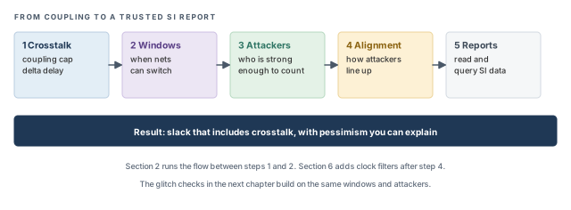
The order matters. We first build a picture of the physics, because every setting later in the chapter only makes sense against it. Then we run the flow, and only then tune windows, attackers and alignment. Reports and scripts come last, because they show the result of all the earlier choices.
Key commands
Table 1 lists the commands and settings of this chapter, grouped by section. Do not try to memorize them now. Each one is explained in its own section, with its default and the cost of misusing it.
| Section | Command or setting | What it does |
|---|---|---|
| 2 Flow | read_lib -cdb |
Reads a noise library (cdB) next to the timing library |
| 2 Flow | set_delay_cal_mode -siAware true |
Turns on SI-aware delay calculation |
| 2 Flow | set_design_mode -process |
Sets node-based defaults; give it first |
| 3 Windows | read_twf |
Reads timing windows from a file instead of computing them |
| 3 Windows | set_si_mode -num_si_iteration, -si_reselection |
Number of SI passes and how victims are reselected |
| 3 Windows | timing_enable_timing_window_pessimism_removal |
Removes common-clock pessimism from timing windows |
| 4 Attackers | set_si_mode -individual_attacker_threshold, -individual_attacker_clock_threshold |
Strength above which an attacker is treated alone |
| 4 Attackers | set_si_mode -accumulated_small_attacker_mode, _factor, _threshold |
Control the merged virtual attacker |
| 5 Alignment | set_si_mode -attacker_alignment |
How attacker windows are aligned to the victim |
| 6 Clocks | set_si_mode -clocks, set_clock_groups |
Clock relationships seen by SI |
| 6 Clocks | set_si_mode -enable_logical_correlation, -unconstrained_net_use_inf_tw |
Logic-aware filtering and windows for unconstrained nets |
| 6 Clocks | set_quiet_attacker, set_si_mode -delta_delay_annotation_mode |
Silence attackers; choose where delta delay is annotated |
| 7 Reports | report_timing -net, report_delay_calculation -si, report_noise -delay |
Show delta delay on paths, arcs and nets |
| 8 Queries | timing_report_enable_si_debug, get_property |
Read SI data in scripts |
1 Crosstalk: the beginner's model
1.1 The concept
Let us consider two long wires side by side, as in Figure 2. The wire we are timing is the victim. A neighbor that can disturb it is an aggressor. Tempus calls it an attacker, so this chapter uses that word.
Any two conductors separated by an insulator form a capacitor. Two parallel wires are exactly that. The longer they run together and the closer they sit, the larger the capacitor. This is the coupling capacitance, Ccpl.
The victim also has capacitance to ground, through the layers above and below it. It also drives the input pins of its receivers, which add their own capacitance. Together these form the victim's total capacitance, Ctot.
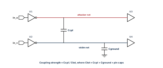
The ratio Ccpl / Ctot is a good first measure of attacker strength. For example, assume Ccpl is 3 fF and Ctot is 75 fF. The ratio is 3 / 75 = 0.04, or 4 %. An attacker at 0.3 % barely matters. One at 4 % can shift the victim's edge noticeably.
Why does the ratio work? When the attacker switches, it injects charge through Ccpl. That charge spreads over all of the victim's capacitance. Thus, the larger Ctot is relative to Ccpl, the smaller the disturbance on the victim.
- Strength is not only
Ccpl / Ctot. The attacker's slew and drive, and the victim's driver, also matter. The ratio is a filter, not the final answer. - An attacker matters only if it can switch while the victim switches. Two nets with large coupling but far-apart switching times add no delta delay.
- A strong victim driver fights back. It restores the victim quickly, so the same coupling hurts a weak driver more than a strong one.
1.2 How it changes delay
Figure 3 shows the three cases for a rising victim. The numbers are illustrative, but the directions are always the same.
- Attacker quiet – the victim switches with its base delay. In the figure it arrives at 1.20 ns.
- Attacker switches the opposite way – the coupling fights the victim's transition. The edge is slower, and the arrival moves later. This is a slow-down.
- Attacker switches the same way – the coupling helps the victim. The edge arrives earlier. This is a speed-up.
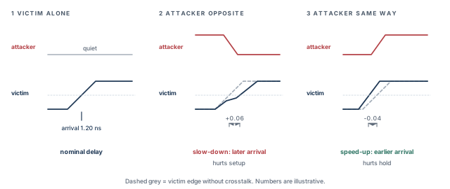
Why does direction matter? Let us think about the voltage across Ccpl. When both nets rise together, the voltage across the capacitor barely changes, so little charge has to move. The victim's driver has less work to do, and the edge is fast. When the nets move in opposite directions, the voltage across Ccpl changes twice as much. The driver must move more charge, and the edge is slow.
The change in arrival is the delta delay. In the figure, the slow-down case arrives at 1.20 + 0.06 = 1.26 ns. The speed-up case arrives at 1.20 − 0.04 = 1.16 ns. The delta delay is added on top of the base delay of the net and its driver.
1.3 Which direction hurts which check
A setup check asks whether data arrives early enough before the capture edge. A hold check asks whether data stays stable long enough after it. Thus, setup suffers when data is late, and hold suffers when data is early.
However, crosstalk also hits clock nets. A clock that arrives late at the capture flop gives data more time, which helps setup. The same late capture clock hurts hold. Figure 4, shown after the example below, collects all the cases.
Let us check one row with numbers. Assume the capture edge is at 0 ns, and hold needs data to change at least 0.05 ns after it. Data changes at 0.12 ns, so hold slack is 0.12 − 0.05 = 0.07 ns. A speed-up of −0.04 ns on data drops the slack to 0.03 ns. A slow-down of 0.05 ns on the capture clock moves the requirement to 0.10 ns. The slack becomes 0.08 − 0.10 = −0.02 ns. Both deltas hurt hold, from different nets.
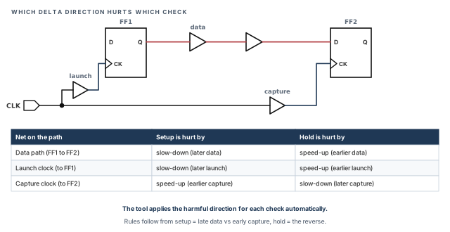
The tool applies the harmful direction for each check on its own. You do not set this per path. However, you must understand it to read a report. For example, if a hold violation comes from a slow capture clock, shielding or spacing the data net will not remove it. The coupling to fix sits on the clock net.
2 Running SI delay analysis
2.1 What SI analysis needs
SI analysis needs three things beyond base timing.
- Noise data for each library cell. It describes how each cell behaves when its pins see noise. It comes as a separate cdB file, or inside the library as CCS-N or ECSM-SI.
- Coupled parasitics. The SPEF must contain the coupling capacitors between nets. A SPEF with only grounded caps gives the tool nothing to work with.
- The SI switch. Delay calculation must be told to consider crosstalk with
set_delay_cal_mode -siAware true.
If any one is missing, the run typically still completes. However, the delta delays are then zero or wrong, and the report can look normal. Thus, check all three before trusting an SI report.
2.2 The flow
The script below is a complete SI timing run. Three points about it matter before we read it:
set_design_mode -processcomes first, because it sets node defaults that later settings build on.set_si_mode -individual_attacker_threshold 0.015sets the attacker filter. Section 4 explains it in detail.-separate_delta_delay_on_data trueand-enable_delay_report trueonly affect reporting. They are explained in section 7.
tempus> set_design_mode -process 28          ;# node defaults first (28 nm)
tempus> read_lib typ.lib -cdb typ.cdB        ;# timing library plus noise data
tempus> read_verilog dma_mac.v               ;# gate-level netlist
tempus> set_top_module dma_mac               ;# link the design
tempus> read_sdc constraints.sdc             ;# clocks and I/O constraints
tempus> read_spef cell.spef.gz               ;# parasitics including Ccpl
tempus> set_si_mode -individual_attacker_threshold 0.015   ;# 1.5 % ratio
tempus> set_si_mode -num_si_iteration 3      ;# three SI passes
tempus> set_si_mode -separate_delta_delay_on_data true   ;# data delta apart
tempus> set_si_mode -enable_delay_report true            ;# keep attacker tables
tempus> set_delay_cal_mode -siAware true     ;# turn on SI delay calculation
tempus> report_timing                        ;# paths now include delta delay
tempus> report_delay_calculation -si -from inst1/A -to inst1/Y   ;# one arc
tempus> report_noise -delay max              ;# delta delay per net (or min)
Let us walk through what the tool does, in outline, when report_timing runs. First, it calculates base delays for every arc. Second, it builds timing windows for every net. Third, it finds the attackers of each victim, filters them by strength and window overlap, and computes delta delays. Finally, it adds the deltas to the arrivals and reports the slack. Sections 3 to 5 explain the middle steps.
Figure 5 shows both halves of this picture. The top row is what you write in the script, in order. The bottom row is what the tool then does inside every timing update.
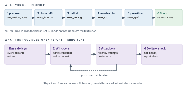
The three report commands look at the same result at three levels. report_timing shows whole paths. report_delay_calculation -si shows one arc and its attackers. report_noise -delay max lists the nets with the largest delta delay, and -delay min lists the largest speed-ups.
Reading a SPEF without coupling capacitance, or forgetting -siAware true, can give a clean report with zero delta delay. The run looks fine, and crosstalk is simply missing. A quick check is report_noise -delay max: an empty or all-zero list on a large block is a warning sign.
set_delay_cal_mode -siAware true.3 Timing windows
3.1 The concept
An attacker can only disturb a victim if both switch at about the same time. The range of times in which a net can switch is its timing window (TW). It runs from the earliest to the latest possible arrival on that net.
Why is it a range and not a single time? A net is usually reached by many paths. Some are short and some are long. Each path gives a different arrival. Thus, the net can switch anywhere between the earliest and the latest of them.
Let us consider Figure 6. The victim V can switch between 2.0 and 2.6 ns. Attacker A1 can switch between 2.3 and 3.0 ns. The windows overlap from 2.3 to 2.6 ns, so A1 counts. Attacker A2 switches between 3.4 and 4.0 ns. It never meets V, so it is ignored.
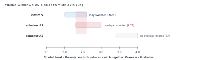
Thus, timing windows are the main tool against pessimism. Without them, every coupled neighbor would count, whether or not it could ever switch at the same moment.
3.2 Where windows come from
The tool builds timing windows internally from its own arrivals. This is the normal case, and it keeps the windows consistent with the current constraints and parasitics.
Alternatively, you can read them from a file with read_twf. This is useful when the windows were computed elsewhere, for example in another run. However, the file must match the current design and constraints. Windows from an older netlist describe a different circuit, and the delta delays built on them can be wrong.
3.3 The loop between windows and delta delay
There is a loop here. Delta delay changes arrivals, and arrivals define the windows that decide delta delay. The tool cannot know the final windows before it knows the deltas. It breaks the loop by iterating.
By default it starts with infinite timing windows, so every attacker overlaps. It then computes real arrivals, which shrink the windows. The alternative is to start noiseless and let the windows grow as delta delay is added. Figure 7 shows the default.
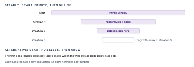
The default is the safe direction. In principle, starting from infinite windows can only overestimate delta delay, not miss it. Each pass then removes some of that overestimate. Starting noiseless converges from the optimistic side instead.
3.4 Command breakdown
tempus> set_si_mode -num_si_iteration 3       ;# one more pass than the default
tempus> set_si_mode -si_reselection slack ;# refine the most critical victims-num_si_iterationsets the number of SI passes. The default is 2. A third pass usually removes a little more pessimism. However, each pass repeats delay calculation, so runtime grows.-si_reselection {delta_delay | slack | xcap_ratio}decides which victims are reselected for refinement in the next pass. The default isslack, so, typically, victims on the most critical paths are refined first. As their names suggest,delta_delayranks victims by delta delay andxcap_ratioby coupling ratio.
Which one should you use? slack is a good default, because effort goes where it changes signoff results. The other two are useful when you are studying noise itself rather than closing timing.
After reselection, a critical victim gets real windows, but its non-critical attackers keep their wide windows. Thus, some pessimism can remain on that victim even after several passes. If a few victims stay pessimistic, look at their attackers, not only at the victim.
3.5 Removing common-clock pessimism from windows
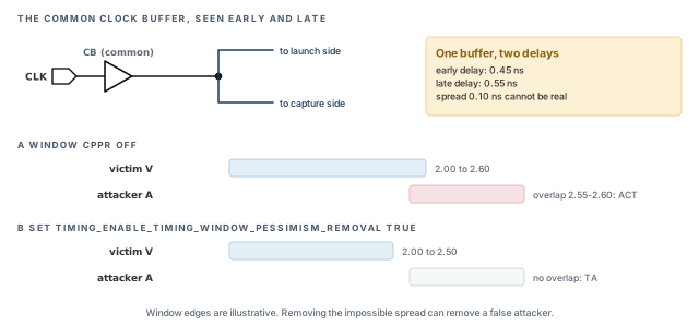
Windows carry their own pessimism. In Analysis Modes, CPPR and AOCV we will meet early and late derates. They make the same clock buffer look fast for one check and slow for another. On the clock path shared by launch and capture, this is impossible. One buffer cannot be fast and slow at once.
The same effect widens timing windows needlessly. Setting the variable below removes that difference:
tempus> set timing_enable_timing_window_pessimism_removal true ;# TW CPPR onIt removes the early/late derate difference on the common clock. It also removes the min/max SI difference on the common clock, but only for hold checks. Narrower windows mean fewer false overlaps, and so fewer false delta delays.
Let us consider Figure 8. A common clock buffer has an early delay of 0.45 ns and a late delay of 0.55 ns. Without window CPPR, the victim window carries that 0.10 ns spread and runs from 2.00 to 2.60 ns. Attacker A switches between 2.55 and 2.90 ns. It overlaps the last 0.05 ns of the window, so it counts.
With the variable set, the impossible spread is removed. In this example the late edge moves in by 0.10 ns, so the window ends at 2.50 ns. Attacker A no longer overlaps, and its status becomes TA. The exact shrink depends on the design; the numbers here are illustrative.
4 Choosing which attackers count
4.1 The concept
A victim may have dozens of coupled neighbors. Treating each one separately is slow, and most are tiny. Thus, the tool sorts attackers by strength, Ccpl / Ctot, as in Figure 9.
Strong attackers are kept as individual attackers. Each one is aligned on its own and appears by name in reports. Weak attackers are not thrown away. Instead, they are merged into one combined attacker, so their total effect is still counted.
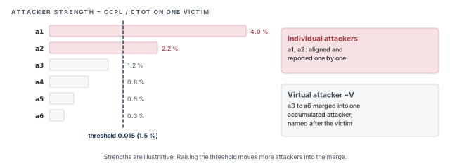
Let us check the figure with numbers. The threshold is 0.015, or 1.5 %. Attackers a1 at 4.0 % and a2 at 2.2 % are above it, so they stay individual. Attackers a3 to a6 sum to 1.2 + 0.8 + 0.5 + 0.3 = 2.8 %. That is larger than a2 alone. Thus, merging rather than dropping them matters.
4.2 Command breakdown – individual attackers
set_si_mode -individual_attacker_threshold– an attacker whose ratio is above this value is an individual attacker. A lower value keeps more attackers separate, which is more detailed but slower. A higher value merges more of them.set_si_mode -individual_attacker_clock_threshold– the same rule, but for victims that are clock nets. Clocks often deserve a tighter limit, because a clock delta affects every flop the clock reaches.- Attackers below the threshold merge into one virtual attacker named
~<victim>. For a victimVit appears as~Vin attacker tables.
4.3 Command breakdown – the virtual attacker
The virtual attacker has three controls of its own, all on set_si_mode.
-accumulated_small_attacker_mode {current | cap}– how the small attackers are combined. As the names suggest,currentworks from injected current andcapfrom coupling capacitance. The default iscurrentat 45 nm and below, andcapabove 45 nm.-accumulated_small_attacker_factor– a value from 0 to 1 that scales the combined effect. Typically, a value near 1 keeps close to the full sum, and smaller values reduce it. Reduce it only with a reason, because it lowers coverage.-accumulated_small_attacker_threshold– a limit that decides when the combined small attackers matter. Confirm its default withhelp set_si_modein your installation. Setting it to1.01disables the virtual attacker.
tempus> set_si_mode -individual_attacker_threshold 0.015         ;# data victims: 1.5 %
tempus> set_si_mode -individual_attacker_clock_threshold 0.01    ;# clock victims: 1 %
tempus> set_si_mode -accumulated_small_attacker_factor 1.0       ;# keep full sum
The clock threshold value above is illustrative. It shows a common pattern: a tighter limit on clocks than on data.
It is better to lower -individual_attacker_threshold than to disable the virtual attacker. The reason is coverage: many small attackers together can still add real delay, as the 2.8 % example shows.
~<victim>. The individual thresholds trade runtime against detail. Small attackers stay covered unless you disable the virtual attacker.5 Aligning attackers to the victim
5.1 The concept
Overlap alone is not enough. The tool must also decide where in the victim's window to place the attacker edges. The delta delay is largest when the attacker switches near the middle of the victim's transition. Thus, the alignment choice moves results between optimistic and conservative. This is attacker alignment.
First, two terms that this choice depends on.
- GBA, graph-based analysis, times all paths through a pin together. At each pin it keeps the worst arrival and slew. It is fast, but it can be pessimistic for any single path.
- PBA, path-based analysis, re-times one path with that path's own arrivals and slews. It is slower and usually less pessimistic.
A GBA result bounds PBA when PBA slack is never worse than GBA slack. This property matters for signoff. If GBA bounds PBA, a clean GBA run proves that PBA would also be clean. If it does not, GBA can pass while some path fails in PBA.
5.2 The four modes
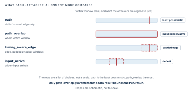
set_si_mode -attacker_alignment takes one of four values. Figure 10 sketches what each one compares.
| Mode | Aligns attackers to | Pessimism | GBA bounds PBA? |
|---|---|---|---|
path |
The victim's worst edge | Least pessimistic | No |
path_overlap |
The whole victim timing window | Most conservative | Yes |
timing_aware_edge |
The edge, with padded attacker windows | Typically in between | Not guaranteed by the mode |
input_arrival (default) |
Arrivals at the driver inputs, with 2-sigma attacker windows | Typically in between | Not guaranteed by the mode |
Let us look at each mode in turn.
pathlooks only at the victim's worst edge. An attacker counts if it can switch at that edge. This is the least pessimistic choice. However, GBA does not bound PBA here. Typically, this is because a PBA path can see a different edge.path_overlapcompares attackers with the whole victim window. Any overlap anywhere counts. This is the most conservative choice, and it is the one where GBA bounds PBA.timing_aware_edgeis edge-based, but it pads the attacker windows. Clock nets and nets with timing exceptions use the full victim window. Other nets use the critical region plus the maximum CPPR. In PBA, the padding uses the path's own CPPR instead.input_arrivalis the default. It works from arrivals at the driver inputs, and it uses 2-sigma attacker windows. With SOCV, GBA uses the mean window and PBA uses the mean edge. Sigma and SOCV are covered in SOCV and Wire Variation.
In PBA, the tool always annotates delta delay per attacker overlap, whatever the mode. Thus, PBA results reflect each attacker's real overlap with that path.
A common approach is to run PBA-SI only on paths that are critical in GBA. This keeps runtime low, because PBA is applied to few paths. For PBA-based signoff, use path_overlap, so the GBA result is a safe upper bound on the paths you did not re-time.
Switching to path because it shows the best slack. In this mode, GBA does not bound PBA, so a passing GBA run does not prove that every path passes. Change the alignment mode only with a clear reason, and record it with the signoff settings.
path_overlap is the safe choice when GBA must bound PBA.6 Clocks, exclusivity and other filters
The settings in this section tell the tool facts about the design that it cannot work out alone. Each one removes or reduces attackers. Thus, each one must describe real behavior, or it hides real violations.
6.1 Synchronous and asynchronous clocks
set_si_mode -clocks {asynchronous | synchronous} tells the tool how to relate the windows of different clocks. The default is synchronous.
Typically, synchronous clocks keep their real phase relationship. Their windows can be compared on one time axis, as in Figure 6. Asynchronous clocks have no fixed relationship. An attacker on one clock can switch at any moment relative to a victim on the other. Thus, their windows can meet anywhere, which is more pessimistic.
6.2 Clock groups
set_clock_groups affects SI as well as timing. Its three options mean different things physically, so they have different SI effects. Figure 11 shows the decision.
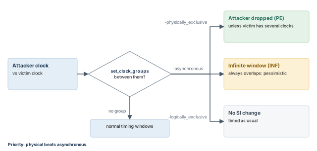
-logically_exclusive– no change to SI. The two clocks cannot be active together in logic, for example through a mux. However, both clock signals still exist on the chip, and their wires still couple.-asynchronous– the attacker gets an infinite timing window (status INF). The tool cannot rule out any alignment. This is safe but pessimistic.-physically_exclusive– the attacker is dropped (status PE). The two clocks never exist on silicon at the same time, for example two clocks defined on one port for different modes. However, this is not applied when the victim has multiple clocks.- Priority – when both apply, physical exclusivity beats asynchronous.
- If an attacker is both physically exclusive and has a synchronous window, only the synchronous one is checked.
Declaring clocks physically exclusive because it removes violations. If both clocks can run at once, their wires do couple, and the dropped attackers were real. Use -physically_exclusive only when the clocks truly cannot coexist on silicon.
6.3 Logical correlation
Let us consider Figure 12. Net S drives a buffer and an inverter. The attacker always switches the same way as S; the victim always switches the opposite way. Thus, a same-direction event between them can never happen.
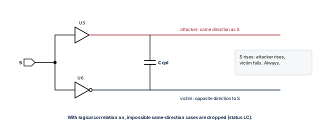
Without logic awareness, the tool would still consider a speed-up between these nets. That speed-up is pessimism for hold.
set_si_mode -enable_logical_correlation true lets the tool drop such impossible cases (status LC). The default is false. It only traces through inverters and buffers. Correlation through other gates, such as a NAND, is not detected.
6.4 Unconstrained nets
A net with no timing constraint has no real window, because no path reaches it with a known arrival. The tool must still decide whether it can attack.
set_si_mode -unconstrained_net_use_inf_tw gives such nets an infinite window. The default is true, which is safe: an unconstrained net is assumed to switch at any time. Setting it to false stops treating them that way. However, many unconstrained nets in a design usually mean missing constraints, which should be fixed first.
6.5 Quiet attackers
Sometimes you know that an attacker cannot switch, for example a static configuration net. set_quiet_attacker declares that, and the attacker's status becomes UF (user).
tempus> set_quiet_attacker -victim v -attacker {a b} -transition rise ;# a, b quiet for rise-victimnames the victim net the setting applies to.-attackernames one or more attackers to silence for that victim.-transition– as the name suggests, limits the setting to one transition, hererise. Confirm the exact effect withhelp set_quiet_attacker.
Declaring an attacker quiet only to clear a violation. If the attacker can in fact switch, the violation is real and is now hidden. Only silence attackers you can justify in writing.
6.6 Where delta delay is annotated
set_si_mode -delta_delay_annotation_mode {lumpedOnNet | arc} decides where delta delay is placed in the timing graph. The default is arc. As the names suggest, arc annotates it on the timing arcs, and lumpedOnNet lumps it onto the net.
This changes where the delta appears in reports, and so how you read them. Keep the default unless a downstream step needs the other form, and use the same mode in runs you compare.
7 Reading SI reports
7.1 Showing delta delay in path reports
By default, the delta delay on data nets is folded into the delay column. Delta on clock nets is always shown separately. Thus, a data path report can hide a large delta inside an ordinary-looking delay.
To see data delta delay as its own column, use all three settings below. Each does one part of the job.
# add the incr_delay column to path reports
tempus> set_global report_timing_format {hpin cell slew incr_delay delay arrival}
tempus> set_si_mode -separate_delta_delay_on_data true   ;# split delta from base delay
tempus> report_timing -net ;# show net arcs too- The
report_timing_formatsetting adds theincr_delaycolumn, where the delta appears. -separate_delta_delay_on_data truetells the tool to keep the data delta apart from base delay.-netshows net arcs as their own rows, so you can see on which net the delta sits.
Figure 13 compares the two report forms for one short path. The arrivals are the same in both. Only the visibility of the delta changes.
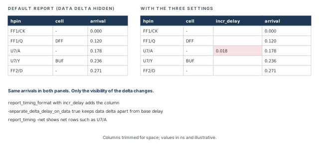
7.2 The attacker table
report_delay_calculation -si prints an attacker table for one arc. The table appears only when set_si_mode -enable_delay_report true was set before the run. Without it, the command reports the arc delay but not the attackers behind it.
Each attacker has a status code. Table 3 lists them, and the earlier sections explain where each one comes from.
| Code | Meaning | Typical source |
|---|---|---|
| SY | Synchronous timing window | Normal window alignment |
| INF | Infinite timing window | Asynchronous clocks or unconstrained nets |
| ACT | Active: the attacker contributes | Overlap found; delta counted |
| PE | Physically exclusive: dropped | set_clock_groups -physically_exclusive |
| UF | User: set quiet | set_quiet_attacker |
| SB | Small bump: too weak to matter | Very small effect on the victim |
| TA | No timing window overlap | Windows never meet |
| LC | Logical correlation: impossible event dropped | -enable_logical_correlation true |
Reading the codes is the fastest way to judge a delta. An ACT attacker with a large ratio is a real contributor. INF attackers deserve a second look, because their windows may be wider than reality.
7.3 Net-level delta delay
report_noise -delay max (or min) lists delta delay per net. Use max to look at slow-down and min to look at speed-up. Useful options:
-nets– limit the report to named nets.-threshold– only report nets above this delta. The default is 10 ps.-sortBy IncrDelay– sort by delta delay.
tempus> report_noise -delay max -threshold 0.02 -sortBy IncrDelay ;# above 20 ps (ns units)7.4 A debug order that works
Figure 14 shows a simple order for working through SI violations. It moves from the whole design down to one arc, and then to a decision.
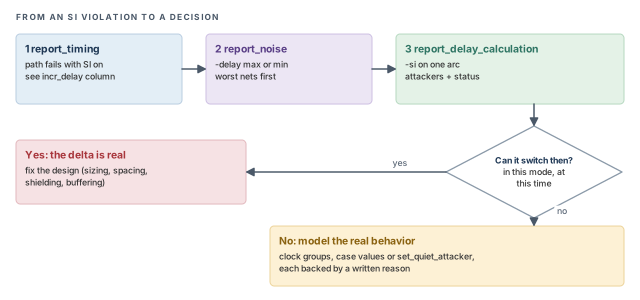
Start from report_noise -delay max to find the nets with the largest slow-down. Then use report_delay_calculation -si on one of them to see which attackers caused it. Only then decide whether the delta is real.
-enable_delay_report true. Read status codes before deciding on a fix.8 Querying SI data in scripts
Reports are for reading; properties are for scripts. A script can, for example, list every victim on failing paths that has more than three active attackers. First enable SI debug data:
tempus> set timing_report_enable_si_debug true ;# required before SI get_propertyWithout this variable, the SI properties are not available, and get_property returns nothing useful.
On a PBA path. Get a path collection with report_timing -retime path_slew_propagation -collection. Then follow this chain:
timing_pointsof the path – one entry per pin on the path.si_objectof a timing point – the SI data at that point.- On the
si_object:hierarchical_name,num_attackersandattackers. - On each attacker:
is_activeandstate.
On a GBA pin. Read the pin property si_victim, with -view in a multi-view run. Its fields are view_type, transition and num_active_attackers.
Figure 15 maps both chains side by side. Read it top to bottom: each arrow is one get_property step.
tempus> set p [report_timing -retime path_slew_propagation -collection]   ;# PBA path
tempus> set tp [get_property $p timing_points]           ;# points on the path
tempus> set si [get_property [lindex $tp 3] si_object]   ;# SI data at one point
tempus> get_property $si num_attackers ;# attackers on that netThe property names come from the tool. The exact argument order of get_property in your installation can be checked with help get_property.
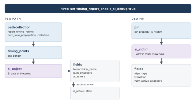
si_object.timing_report_enable_si_debug true, then walk timing_points to si_object to attackers on PBA paths, or read si_victim on GBA pins.9 Worked example: a hold failure caused by speed-up
The situation. A block passes hold without SI. With SI on, one path fails hold by 15 ps. Let us find the cause and decide on the fix. We follow the order in Figure 14.
Step 1 – confirm SI is really on and reported
Before trusting the failure, we make sure SI is on and that the reports will show the attackers. Without these settings, later steps show too little.
tempus> set_delay_cal_mode -siAware true                  ;# SI delay calculation
tempus> set_si_mode -enable_delay_report true             ;# keep attacker tables
tempus> set_si_mode -separate_delta_delay_on_data true    ;# show data delta
# add the incr_delay column to path reports
tempus> set_global report_timing_format {hpin cell slew incr_delay delay arrival}
Step 2 – find the net with the largest speed-up
A hold failure comes from early data or a late capture clock. We start with speed-up on data nets, so we use -delay min.
tempus> report_noise -delay min -sortBy IncrDelay ;# speed-up per net, sorted by deltaAssume the top net on the failing path is u_ctrl/n42, with a delta of −0.018 ns. Without that delta, the path would pass by 3 ps. Thus, this net is the right place to look.
Figure 16 draws this hold check. Assume the hold requirement at FF2/D is 0.200 ns. Without SI, data changes at 0.203 ns, a slack of 0.203 − 0.200 = +0.003 ns. The speed-up of −0.018 ns moves it to 0.185 ns. The slack is now 0.185 − 0.200 = −0.015 ns.
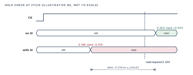
Step 3 – look at its attackers
We now open the arc that drives the net, to see who causes the speed-up.
tempus> report_delay_calculation -si -from u_ctrl/U7/A -to u_ctrl/U7/Y ;# driver arcAttacker Ccpl/Ctot Status
u_dbg/scan_en 0.031 ACT
u_ctrl/n44 0.018 TA
~u_ctrl/n42 0.009 ACTLet us read the table line by line.
scan_enis active, with a ratio of 3.1 %. It is the main contributor.n44is above the 1.5 % threshold, so it is individual. However, it is TA: its window never meets the victim's, so it adds nothing.~u_ctrl/n42is the virtual attacker, holding the small attackers. It adds a little.
Step 4 – reason before fixing
- In functional mode,
scan_enis held constant. However, in this run it is not constrained to a constant value. - If the design team confirms that it cannot switch in this mode, a quiet-attacker setting is justified, with that reason recorded.
- If
scan_encan switch, for example during a mode change, the speed-up is real. The path then needs a real hold fix.
Thus, the first action is a review with the design team, not a constraint change. The cost of a wrong quiet attacker is a hidden real failure. The cost of a needless hold buffer is only a little area.
Step 5 – confirm the result
Whichever branch we take, we re-run the path report and the net list. The goal is to see the change, not to assume it.
tempus> report_timing -early -net                 ;# hold view of the failing path
tempus> report_noise -delay min -nets u_ctrl/n42 ;# delta on the one net we studied- If the attacker was justified as quiet, its status now reads UF, and the delta on
n42shrinks. - If a hold fix was added instead, the delta may stay, but the slack is now positive.
- In both cases, record the decision next to the run, so the next engineer sees why the path passes.
10 Common mistakes and how to catch them
Table 4 gathers the mistakes from this chapter. Each row starts from the symptom you would see first.
| Symptom | Likely cause | Fix |
|---|---|---|
| Zero delta delay everywhere | SPEF without coupling, or -siAware not set |
Read coupled SPEF; set set_delay_cal_mode -siAware true |
No attacker table in report_delay_calculation -si |
-enable_delay_report not set |
Set set_si_mode -enable_delay_report true before the run |
Data delta not visible in report_timing |
Default folds data delta into delay | Use incr_delay format, -separate_delta_delay_on_data true, -net |
| Too many SI violations on async crossings | Asynchronous groups give infinite windows | Check whether the clocks are truly physically exclusive |
| PBA worse than GBA after an alignment change | Mode where GBA does not bound PBA | Use path_overlap for PBA signoff |
| Pessimism left on a critical victim | Its non-critical attackers kept wide windows | Add an iteration; enable window CPPR |
| Real slow-down missing | Virtual attacker disabled with 1.01 |
Keep it enabled; tune thresholds instead |
| Clean SI after a quick fix | Unjustified set_quiet_attacker |
Review every quiet attacker with the design team |
| Hold violation stays after shielding the data net | The delta sits on the capture clock | Check clock nets in the path report |
get_property returns no SI data |
timing_report_enable_si_debug not set |
Set it to true first |
11 Interview preparation
The change in a net's delay caused by a switching neighbor through coupling capacitance.
- Opposite-direction switching gives slow-down; same-direction gives speed-up.
- It is added on top of the base delay of the net and its driver.
On data paths, slow-down hurts setup and speed-up hurts hold; on the capture clock it is the reverse.
- Setup fails when data is too late; hold fails when data is too early.
- A late capture clock helps setup but hurts hold.
Its timing window does not overlap the victim's window.
- Coupling only matters when both nets can switch at the same time.
- Such an attacker shows status TA.
It iterates, starting from infinite windows and shrinking them with real arrivals.
-num_si_iterationdefaults to 2; each extra pass repeats delay calculation.- The alternative starts noiseless and grows the windows.
-si_reselection(defaultslack) picks which victims are refined.
All attackers below the individual threshold, merged into one attacker named ~<victim>.
- It keeps the total effect of many small attackers in the analysis.
- Setting
-accumulated_small_attacker_thresholdto1.01disables it.
path_overlap, because only it guarantees that GBA bounds PBA.
pathis least pessimistic, but GBA does not bound PBA there.- The default is
input_arrival.
set_clock_groups -physically_exclusive do to SI?It drops the attacker, unless the victim has several clocks.
- Asynchronous groups instead give infinite windows. Physical wins over asynchronous.
- Logically exclusive clocks get no SI change, because their wires still coexist.
It removes impossible switching combinations; it only traces through inverters and buffers.
- Enabled with
-enable_logical_correlation true; the default isfalse. - Dropped attackers show status LC.
report_timing shows no delta delay on data nets, though SI is on. Why?Data delta is folded into the delay column by default.
- Add
incr_delayto the format, set-separate_delta_delay_on_data trueand use-net. - Clock delta is always shown separately.
ACT is an active attacker, TA means no window overlap, UF means set quiet by the user.
- The table appears only with
-enable_delay_report true. - PE, UF, TA and LC attackers are removed; SB ones are typically too small to matter. INF ones deserve a second look.
timing_enable_timing_window_pessimism_removal remove?The early/late derate difference on the common clock, and the min/max SI difference there for hold.
- One buffer cannot be both fast and slow at once, so that difference is false.
- Narrower windows mean fewer false overlaps, so fewer false delta delays.
Enable timing_report_enable_si_debug, then follow timing_points, si_object and num_attackers.
- The path comes from
report_timing -retime path_slew_propagation -collection. - On GBA pins, read
si_victiminstead.
Chapter recap
Key takeaways
- Crosstalk adds delta delay: slow-down from opposite switching, speed-up from same-direction switching.
- Setup is hurt by late data and early capture; hold by early data and late capture.
- Only attackers whose timing windows overlap the victim count. Windows shrink over SI iterations.
- Strong attackers are modeled alone; small ones merge into the virtual attacker
~<victim>. - Alignment sets pessimism. Use
path_overlapwhen GBA must bound PBA. - Clock groups, logical correlation and quiet attackers remove attackers that cannot act. Each must match real behavior.
- Reports need explicit settings to show data delta and attacker tables.
Command recap
set_si_mode)| Command or setting | Purpose |
|---|---|
set_delay_cal_mode -siAware true |
Turn on SI delay calculation |
read_lib -cdb, read_twf |
Read noise data; read timing windows |
-num_si_iteration, -si_reselection |
SI passes and reselection rule |
timing_enable_timing_window_pessimism_removal |
Window CPPR |
-individual_attacker_threshold, -individual_attacker_clock_threshold |
Individual attacker limits |
-accumulated_small_attacker_mode, _factor, _threshold |
Virtual attacker controls |
-attacker_alignment, -clocks, set_clock_groups |
Alignment; clock relationships |
-enable_logical_correlation, -unconstrained_net_use_inf_tw |
Correlation; unconstrained nets |
set_quiet_attacker, -delta_delay_annotation_mode |
Quiet attackers; annotation location |
report_timing -net, report_delay_calculation -si, report_noise -delay |
SI reports |
timing_report_enable_si_debug, get_property |
SI queries |
Compact glossary
| Term | Meaning |
|---|---|
| Victim | The net being timed |
| Attacker | A coupled neighbor that can disturb the victim |
| Ccpl / Ctot | Coupling cap over total victim cap; a strength measure |
| Delta delay | Change in delay caused by crosstalk |
| Slow-down / speed-up | Later or earlier arrival due to crosstalk |
| Timing window (TW) | Range of times in which a net can switch |
| Virtual attacker | Merged small attackers, named ~<victim> |
| GBA / PBA | Graph-based and path-based analysis; GBA bounds PBA when PBA slack is never worse |
Practical perspective
On a real block, SI can turn a clean run into hundreds of small violations. Often, a few strong attackers and asynchronous or unconstrained nets cause most of them. Thus, find them first with report_noise -delay, then decide which pessimism is real. Blind fixing costs area and power; blind silencing risks silicon.
What comes next
Crosstalk does not only change delay. On a net that should stay still, it can create a pulse that flips a flop. In Glitch, Overshoot and Undershoot, we look at these noise effects and how Tempus checks them.