Chapter overview
In Signal Integrity Delay Analysis we saw crosstalk on a switching net. It speeds the edge up or slows it down. Now we turn to the other case. A net is meant to sit still at 0 or at VDD, but its neighbor switches. The coupling capacitance pushes a short bump onto the quiet net.
This bump is called a glitch. If it is large enough, the gate that receives it can see a false logic value. A flip-flop might capture it, or a clock pin might see an extra edge. Thus, a glitch can break the function of a chip even when every path meets timing.
A second kind of bump pushes the net outside the supply rails, above VDD or below 0 V. This does not usually change the logic. However, it stresses the thin gate oxide of the transistors, which is a reliability problem.
This chapter teaches both checks. We start with the four bump types and the two places where a bump is measured. Then we run the analysis, set the limits, follow propagation, read the reports and control the result. A worked example on a clock net joins all the pieces at the end.
Learning objectives
- Describe the VL, VH, VLU and VHO noise bumps, and say which attacker edge causes each one.
- Explain the receiver input peak (RIP) and receiver output peak (ROP), and when each check applies.
- Set up a glitch run with noise libraries and the right
set_si_modeswitches. - Set RIP and ROP limits with
set_si_modeorset_glitch_threshold, and predict which setting wins. - Explain how a glitch propagates, where it stops, and how
update_glitchuses timing windows. - Read glitch results with
report_noiseand its filters. - Run an overshoot and undershoot check and report only those failures.
- Control the analysis with quiet attackers, annotated glitches, copied noise data and port boundary conditions.
Chapter roadmap
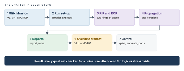
The chapter moves in seven steps, from the basic picture to the controls an engineer uses on a real block. Figure 1 shows the order. Come back to it whenever you lose your place.
Key commands
Table 1 lists the commands covered in this chapter, grouped by section. Do not try to memorize them now. Each one is explained when it is first needed.
| Section | Command | What it does |
|---|---|---|
| 2 Set-up | read_lib -cdb |
Reads timing libraries with their noise data |
| 2 Set-up | set_delay_cal_mode -siAware true |
Turns on crosstalk-aware analysis |
| 2 Set-up | set_si_mode -enable_glitch_report, -enable_glitch_propagation |
Keeps glitch results and lets glitches travel on |
| 2 Set-up | check_noise, update_glitch |
Prepares and runs the glitch analysis |
| 3 Checks | set_si_mode -input_glitch_threshold and related limits |
Sets RIP and ROP limits |
| 3 Checks | set_glitch_threshold |
Sets a failure limit per check point, pin type or glitch type |
| 4 Propagation | set_si_mode -use_infinite_TW |
Keeps infinite timing windows in the second glitch iteration |
| 5 Reports | report_noise |
Reports glitch peaks, failures and summaries |
| 6 Rails | set_si_mode -enable_overshoot_undershoot_glitch |
Turns on the VLU and VHO checks |
| 7 Control | set_quiet_attacker |
Marks attackers as quiet |
| 7 Control | set_annotated_glitch |
Applies a user glitch waveform at a pin |
| 7 Control | set_noise_lib_pin |
Copies noise data from one library pin to another |
| 7 Control | set_driving_cell, set_input_transition, set_load, set_case_analysis |
Set port conditions and silence constant attackers |
1 What a glitch is
1.1 The concept
Two wires that run side by side are never fully separate. The metal of one wire and the metal of its neighbor form a small capacitor. This is the coupling capacitance. When one wire changes voltage, the coupling capacitance pushes a little charge onto the other wire.
Let us consider Figure 2. Gate U1 drives the victim net, which is held at 0 for this clock cycle. Gate U2 drives a neighboring attacker net, which switches. The two wires run side by side, so a coupling capacitance links them.
When the attacker rises, it drags the victim up for a moment. The driver U1 is still holding the victim at 0, so it pulls the charge back out. The victim then settles back to 0. That short bump is the glitch.
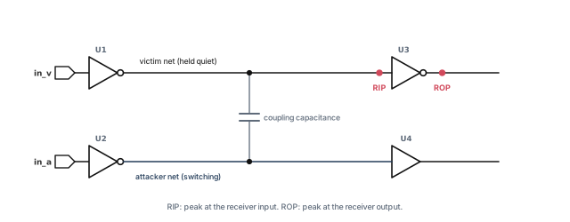
The bump is measured at two points on the receiving gate U3:
- Receiver input peak (RIP) – the peak of the bump at the receiver's input pin. This is the bump on the victim wire itself.
- Receiver output peak (ROP) – the peak of the resulting bump at the receiver's output. This shows how much of the bump the receiver lets through.
1.2 What sets the size of the bump
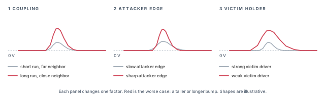
In general, three things decide how big a glitch becomes. They are useful when you later read a report and want to know why one net is worse than another.
- Coupling – a longer parallel run, or a closer neighbor, gives more coupling capacitance and a bigger bump.
- Attacker speed – a sharp attacker edge pushes charge in quickly, before the victim driver can react.
- Victim holding strength – a strong victim driver pulls the charge back out fast, so the bump stays small. A weak one lets it grow.
Figure 3 shows each factor on its own. In each panel only one factor changes, and the red bump is the worse case. Note that a weak holder makes the bump both taller and longer, because the charge drains away slowly.
For example, a long clock-enable wire driven by a small gate, running beside a fast bus, is a classic glitch victim. All three factors work against it.
1.3 The two logic glitches
The direction of the bump depends on the victim's level and the attacker's edge. Figure 4 shows the two cases that can upset logic.
- VL – the victim is low and the attacker rises. The bump goes up from 0 V.
- VH – the victim is high and the attacker falls. The bump goes down from VDD.
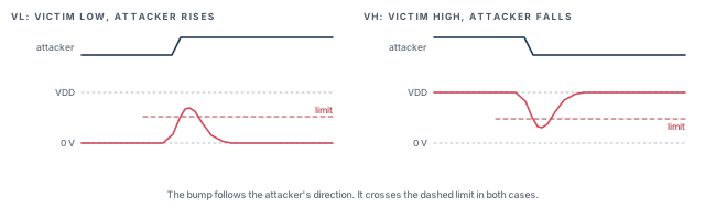
In both cases the bump moves toward the middle of the voltage swing. That is exactly where a receiver decides between 0 and 1. Thus, VL and VH are the two bumps that can change logic.
1.4 Why it matters
For example, assume VDD is 0.9 V and a VL bump peaks at 0.4 V. A receiver with a switching point near 0.45 V is close to flipping. If the bump reaches a flip-flop's data pin while the clock edge arrives, the flop can capture a wrong value. If it reaches a clock pin, the flop can see an extra clock edge.
Neither failure shows up as negative slack. A timing report only looks at when edges arrive. It does not ask whether a net that should stay still really stays still. Thus, a design can pass every timing report and still fail on silicon because of a glitch.
A beginner treats a clean setup and hold report as proof that the block works. Timing reports and glitch reports answer different questions. Both must be clean before signoff.
2 Setting up a glitch run
2.1 Noise data in the libraries
A glitch check is only as good as the noise data the tool has. A normal timing library describes how fast a cell switches. It says little about how a cell reacts to a small bump at its input. Noise data fills that gap.
The libraries must carry noise models in one of three forms: cdB, ECSM-N or CCS-N. ECSM-N and CCS-N are noise extensions of the ECSM and CCS timing models. cdB is a separate noise library file. The -cdb switch of read_lib names a cdB file to read with the timing library.
Noise data is needed for the receiver output check that we meet in Section 3. Without it, the tool can only compare the input bump against a simple limit.
A beginner reads only timing libraries, without -cdb or noise models, and expects a full ROP check. The output peak needs the receiver's noise model. Without it, only the simpler input peak check is possible.
2.2 The basic flow
A glitch run reuses the signal integrity set-up from Signal Integrity Delay Analysis. It then adds two glitch switches and the glitch commands. Let us read the complete flow first.
Keep the glitch run in its own script, separate from the timing run. The settings differ, and a separate script makes it easy to rerun only the noise check after a fix.
tempus> read_lib typ.lib -cdb typ.cdB          ;# timing plus noise data
tempus> read_verilog top.v                     ;# gate-level netlist
tempus> set_top_module top                     ;# link the design
tempus> set_design_mode -process 16            ;# defaults for a 16 nm node
tempus> read_sdc constraints.sdc               ;# clocks and I/O constraints
tempus> read_spef top.spef.gz                  ;# parasitics, incl. coupling caps
tempus> set_delay_cal_mode -siAware true       ;# crosstalk-aware analysis
tempus> set_si_mode -enable_glitch_report true ;# keep glitch data for reports
tempus> set_si_mode -enable_glitch_propagation true   ;# pass glitches on
tempus> check_noise                            ;# check before the glitch run
tempus> update_glitch                          ;# run the glitch analysis
tempus> report_noise -txtfile glitch.txt       ;# write results to a file
The order follows a simple logic. First the tool needs the design: libraries, netlist, constraints and parasitics. The parasitics matter most here, because the SPEF file carries the coupling capacitances. Then come the switches that turn crosstalk and glitch analysis on. Only then does the analysis run. Figure 5 groups the same lines into three stages.
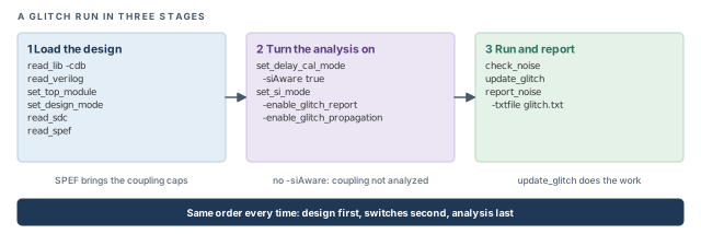
-siAware true in stage 2, coupling is not analyzed, so the glitch report can look clean while hiding real bumps.2.3 Command breakdown
set_delay_cal_mode -siAware true– turns on crosstalk analysis. Without it, coupling is not analyzed, so the glitch check has nothing to work on. A run without this switch can report zero glitches and look perfectly clean.set_si_mode -enable_glitch_report true– asks the tool to keep the glitch results, so thatreport_noisecan show them. Without it, the analysis may run, but there is nothing to report.set_si_mode -enable_glitch_propagation true– lets a glitch travel on through the receiver to the next stage. Section 4 explains the rules and where propagation stops.check_noise– runs before the analysis in this flow. Usehelp check_noiseto see exactly what it checks in your installation.update_glitch– runs the glitch analysis on every victim net. It is the command that does the real work, and it can take noticeable runtime on a large block.report_noise -txtfile glitch.txt– writes the glitch report to a text file. Section 5 covers the other report options.
-enable_glitch_report, check_noise, update_glitch and report_noise.3 Checking a glitch: RIP and ROP
The tool can judge a glitch in two ways. It can look only at the bump on the wire, or it can also model the gate that receives it. Figure 6 shows both measuring points.
3.1 The RIP check
The RIP check compares the bump at the receiver input with a limit. It needs no noise data, so it works with any library. The limit is a ratio of VDD. For example, take a limit of 0.4 with VDD of 0.9 V. Any input bump above 0.4 × 0.9 = 0.36 V fails.
The idea is simple. If the bump stays well below the switching point, no receiver can be fooled. However, the check knows nothing about the receiver. Thus, it is a safe but rough screen.
The limit can be set in three ways:
set_si_mode -input_glitch_threshold <ratio>– one limit for both bump directions. The default is 0.4, that is, 40% of VDD.set_si_mode -input_glitch_vh_thresholdand-input_glitch_vl_threshold– separate limits for VH and VL bumps. Use them when a receiver tolerates one direction better than the other.set_glitch_threshold -failure_point input -threshold_type failure -value <ratio>– the same check through the general threshold command.
When both are given, set_glitch_threshold overrides -input_glitch_threshold. Thus, if a change to -input_glitch_threshold seems to have no effect, look for a set_glitch_threshold elsewhere in the script.
3.2 The ROP check
The RIP check is simple, but it ignores the receiver. A strong receiver may filter a small bump, and a weak one may pass it on. The ROP check models the receiver to find the bump at its output.
To do this, the tool needs VIVO tables – voltage-in, voltage-out data from the noise library. For each receiver pin, they describe how big an output bump each input bump produces.
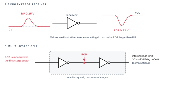
Two details from Figure 6 matter in practice:
- Multi-stage cells – some library cells have two or more internal stages, such as a buffer built from two inverters. For these, ROP is measured at the output of the first stage.
- Internal node limit – for combinational cells, the default limit on that internal node is 30% of VDD.
Note also that the ROP can be larger than the RIP. Thus, passing the RIP check does not prove the output is safe. The reverse is also true. A large RIP can pass the ROP check when the receiver filters it well.
The ROP limits can be set in two ways:
set_si_mode -receiver_peak_limitfor data pins,-receiver_clk_peak_limitfor clock pins and-receiver_latch_peak_limitfor latch pins.set_glitch_threshold -failure_point last -pin_type {clock|data|latch|all} -threshold_type failure -value <ratio>.
Figure 7 shows the kind of curve a VIVO table stores. Small input bumps are filtered: the output barely moves. Around the switching point, the gate starts to act like an amplifier. There, a modest input bump can produce a larger output bump.
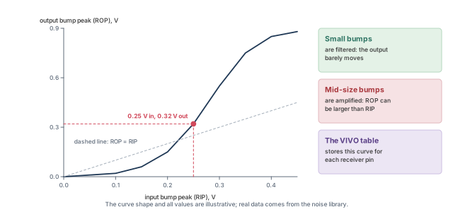
3.3 Command breakdown: set_glitch_threshold
set_glitch_threshold is the general way to set a glitch limit. One command form covers both checks. The options say where the limit applies and to which pins.
tempus> set_glitch_threshold -failure_point input \
          -threshold_type failure -value 0.35        ;# RIP limit: 35% of VDD
tempus> set_glitch_threshold -failure_point last -pin_type clock \
-threshold_type failure -value 0.20 ;# ROP limit on clock pins-failure_point input– the limit applies at the receiver input, so it is a RIP check. It needs no noise data.-failure_point last– the limit applies at the receiver output, so it is an ROP check. It needs VIVO data for the receiver.-pin_type– picks clock, data, latch or all receiver pins. This lets you be strict on clock pins and more relaxed on data pins.-threshold_type failure -value– the failure limit, as a ratio of VDD. With VDD of 0.9 V, a value of 0.20 means 0.18 V.-glitch_type– picks the glitch type, such asvluorvho. We use it for overshoot and undershoot in Section 6.
Figure 8 collects the controls of both checks in one place.
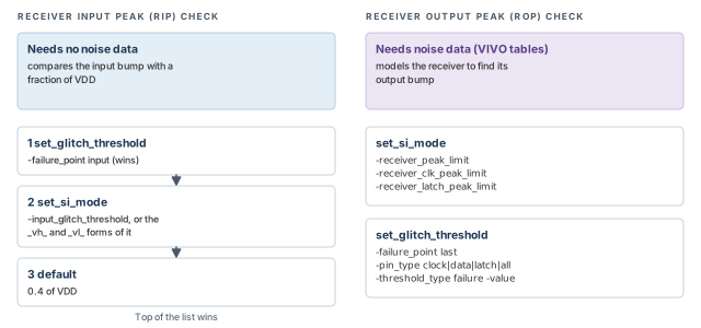
set_si_mode form and a set_glitch_threshold form. For the RIP limit, the general threshold command wins over the set_si_mode setting.What to notice: The -pin_type option lets one command set different ROP limits for clock, data and latch pins.It is better to set a tighter ROP limit on clock pins than on data pins. A bump on a clock pin can create an extra edge at any time. A bump on a data pin only matters near the capture edge.
Mixing the set_si_mode limits and set_glitch_threshold in one script without a plan. Reviewers then cannot tell which limit is active. Pick one style per project and write it down.
4 Glitch propagation and iterations
4.1 How a glitch propagates
A glitch that passes its ROP check is not always harmless. The output bump becomes the input bump of the next gate. That gate may amplify it again. Thus, a bump that is small at one stage can grow into a failure two stages later.
Figure 9 follows a glitch along a chain. Let us walk through it in steps:
- A glitch arrives at
U10. Its output bump passes the ROP check. - Because it passed, the bump is carried forward. It becomes part of the input bump of
U11. - The output bump of
U11fails the ROP check. It is reported as a failure atU11. - A failing glitch is not passed on. Thus,
U12receives no glitch from this source.
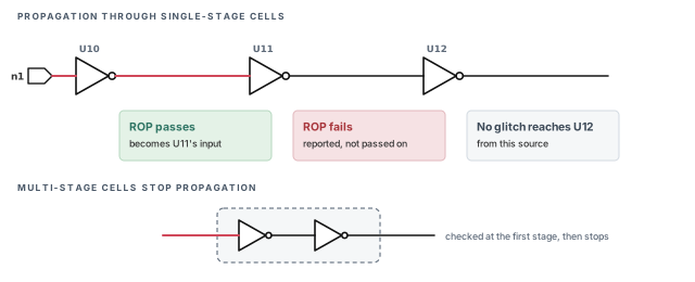
The rules are short:
- Glitches propagate through single-stage cells only. A multi-stage cell is checked at its first stage, and the glitch does not travel through it.
- A failing ROP is not propagated. It is already a reported failure, so carrying it further would count the same problem twice.
- Propagation runs automatically inside
update_glitch. It also runs when-enable_glitch_propagation trueis set beforereport_timingorupdate_timing.
Propagation explains a common surprise. A net can fail even though its own coupling is small. The bump on it may have come from an earlier stage. Look one or two stages back before deciding on a fix.
4.2 Timing windows across iterations
A timing window is the time range in which a net can switch. Signal Integrity Delay Analysis used timing windows to decide which attackers can act together. The glitch analysis uses them in the same way.
Let us consider Figure 10. Two attackers, A1 and A2, couple onto one victim. Assume each alone gives a bump of 0.15 V (illustrative). If both can switch at any time, they may switch together, and the bumps can add up to about 0.30 V. With real windows, A1 switches only between 0.2 and 0.7 ns. A2 switches only between 1.2 and 1.7 ns. They never overlap, so the bumps cannot add, and the worst bump stays near 0.15 V.
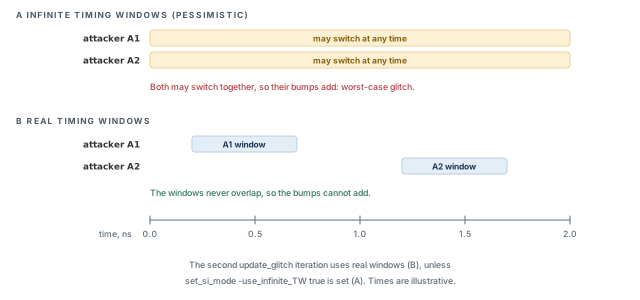
The two cases have names. Infinite timing windows assume every attacker can switch at any time. This is pessimistic but always safe. Real timing windows come from the timing analysis itself. They are accurate, but only as good as the constraints.
update_glitch runs in iterations. Its second iteration uses the real timing windows. To keep infinite windows in that iteration as well, use the -use_infinite_TW switch of set_si_mode.
tempus> set_si_mode -use_infinite_TW true ;# no window filtering in iteration 2Infinite windows are the safe, pessimistic choice. They are useful when the timing windows themselves are not yet trusted, for example before the constraints are clean. Once the constraints are reviewed, switch back to real windows to remove false failures.
update_glitch iteration uses real windows unless -use_infinite_TW true is set.5 Reporting glitches
All glitch results come out through report_noise. A full report on a large block can list many thousands of nets. Thus, the options that filter the report matter as much as the analysis itself.
Table 2 lists the options for glitch work. Use help report_noise to see the exact values each option accepts.
| Option | What it does | When to use it |
|---|---|---|
-txtfile <file> |
Writes the report to a text file | Always, so results can be compared between runs |
-failure |
Reports only failing glitches | First look: the list you must fix |
-threshold <value> |
Filters the report by a threshold value | To hide small, harmless bumps |
-nets <list> |
Reports only the listed victim nets | Debugging a few known nets |
-view <view> |
Reports one analysis view | Multi-view runs, one corner at a time |
-histogram |
Adds a histogram summary of the results | Seeing the overall spread of bumps |
-format |
Selects the report format | Matching a script that parses the report |
-style extended |
Gives the extended, more detailed report style | Understanding why one net fails |
-overshoot_undershoot |
Reports only VLU and VHO results | The reliability check in Section 6 |
The usual order of work is from wide to narrow. A histogram gives the overall shape. The failure list gives the work items. The extended style on a few nets explains the cause. Figure 11 shows this narrowing.
tempus> report_noise -histogram -txtfile glitch_hist.txt    ;# overall picture
tempus> report_noise -failure -txtfile glitch_fail.txt      ;# failures only
tempus> report_noise -nets {n_ctrl n_en} -style extended \
          -txtfile glitch_detail.txt                       ;# two nets in detail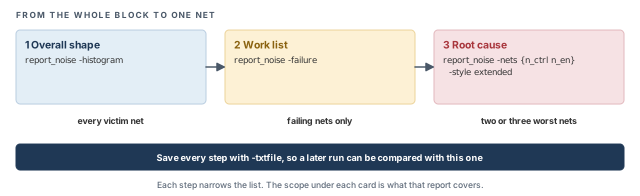
Start with -failure to get the list you must fix. Then use -nets with -style extended on the worst nets to see why they fail. Save every report with -txtfile, so you can prove later that a fix really worked.
report_noise is the single window onto glitch results. Filter with -failure, -nets, -threshold and -view, and save with -txtfile.6 Overshoot and undershoot
6.1 The concept
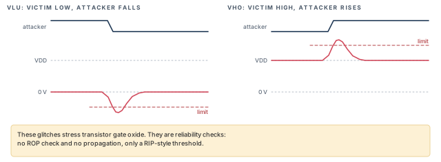
So far the bump moved toward the middle of the swing. The attacker can also push the victim the other way – outside the supply rails. This happens when the attacker moves toward the rail where the victim already sits. Figure 12 shows both cases.
- VLU (victim low, undershoot) – the victim is low and the attacker falls. The victim dips below 0 V.
- VHO (victim high, overshoot) – the victim is high and the attacker rises. The victim rises above VDD.
A simple way to remember the four types is a two-by-two grid. The victim is low or high. The attacker moves toward the victim's level or away from it. Moving away gives VL or VH, which threaten logic. Moving toward gives VLU or VHO, which threaten reliability.
6.2 Why it matters
A bump outside the rails does not usually flip the logic. A low net pushed even lower is still a clear 0. However, it puts extra voltage across the transistor gate oxide. Repeated stress of this kind wears the oxide over the chip's life. Thus, VLU and VHO are reliability checks, not logic checks.
Because of this, they work differently from VL and VH:
- There is no ROP check. The receiver output does not matter, because the logic does not change.
- There is no propagation. Nothing is passed to the next stage.
- Only a RIP-style threshold is applied, on the bump at the receiver input.
6.3 The flow
The flow is the glitch flow with one more switch and two limits. Let us read it.
tempus> read_lib typ.lib -cdb typ.cdB             ;# timing plus noise data
tempus> read_verilog top.v                        ;# netlist
tempus> set_top_module top                        ;# link
tempus> read_sdc constraints.sdc                  ;# constraints
tempus> read_spef top.spef.gz                     ;# parasitics
tempus> set_delay_cal_mode -siAware true          ;# crosstalk-aware
tempus> set_si_mode -enable_overshoot_undershoot_glitch true \
          -enable_glitch_report true              ;# VLU/VHO on, keep results
tempus> set_glitch_threshold -glitch_type vlu -value 0.3   ;# undershoot limit
tempus> set_glitch_threshold -glitch_type vho -value 0.3   ;# overshoot limit
The limits are set before the run. The analysis and the filtered report then follow.
tempus> update_glitch                             ;# run the analysis
tempus> report_noise -failure -txtfile vlu_vho.rpt \
          -overshoot_undershoot                   ;# rail failures only
6.4 Command breakdown
set_si_mode -enable_overshoot_undershoot_glitch true– turns on the VLU and VHO checks. Without it, bumps outside the rails are not checked at all.set_glitch_threshold -glitch_type vlu|vho -value <ratio>– sets the limit for each type. The value is a ratio of VDD, like the input limit. With VDD of 0.9 V, a value of 0.3 typically means a bump of 0.27 V beyond the rail. Confirm the reference point withhelp set_glitch_threshold.set_si_mode -input_glitch_threshold 0.3– an alternative way to set one limit, also a VDD ratio, with a default of 0.4.report_noise -overshoot_undershoot– reports only the VLU and VHO results. This keeps the reliability list separate from the logic list.
Setting both set_glitch_threshold -glitch_type and -input_glitch_threshold, and expecting the second to apply. set_glitch_threshold overrides -input_glitch_threshold. Keep one method per script so the active limit is obvious.
-overshoot_undershoot isolates them in the report.7 Controlling the analysis
Real blocks need some control over the analysis. Some attackers are known to be static. Some noise comes from outside the block. Some library pins lack noise data. The ports need realistic conditions. This section covers each case.
7.1 Quiet attackers
Sometimes the designer knows an attacker cannot switch while the victim matters. For example, a scan-enable net is static in functional mode. Counting it as an attacker adds a bump that can never happen. set_quiet_attacker tells the tool to ignore such attackers.
tempus> set_quiet_attacker -victim n_ctrl                   ;# all attackers of n_ctrl
tempus> set_quiet_attacker -attacker n_scan_en ;# n_scan_en on all victims-victim <net>alone – every attacker of that victim is quiet. Use it when the victim itself does not matter, for example a net that is only used in test mode.-attacker <net>alone – that attacker is quiet on every victim. Use it when one net is known to be static, such as a configuration net.
In the reports, these attackers show the status code UF, which marks a user setting. Thus, a reviewer can always see which results were changed by hand. Figure 13 compares the two forms.
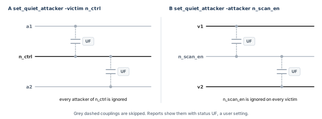
-victim, every coupling onto n_ctrl is skipped. With -attacker, every coupling from n_scan_en is skipped, on all of its victims.What to notice: The scope differs: one victim with all its neighbors, or one attacker with all its victims.Quieting an attacker without proof that it is static. The glitch disappears from the report, but not from the silicon. Keep a written reason for every set_quiet_attacker.
7.2 Annotated glitches
Some glitches come from outside the analysis – for example, noise arriving at a block's input port from the top level. The block-level run cannot compute it, because the top-level wires are not in the block. set_annotated_glitch applies a known glitch waveform at a pin. Figure 14 plots the example used in the command below, from its three time and voltage pairs.
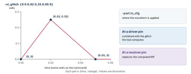
tempus> set_annotated_glitch -port in_cfg \
-vl_glitch {0 0 0.02 0.25 0.05 0} ;# time/voltage pairs, illustrative-port <pin>– where the glitch is applied.-vl_glitchor-vh_glitch– the glitch as a piecewise linear (PWL) list of time and voltage pairs, written inside braces. In the example, the bump starts at 0 V and peaks at 0.25 V at time 0.02. It returns to 0 V at 0.05.
Where the pin sits decides what happens:
- At a driver – the annotated glitch is combined with the glitch the tool computes.
- At a receiver – the annotated glitch overrides the computed RIP.
- A VH waveform is written starting from 0 V, in the same way as a VL waveform.
7.3 Copying noise data between pins
A library cell may lack noise data on a pin. Without it, the ROP check cannot run on that receiver. If a similar pin has good data, set_noise_lib_pin copies it across.
tempus> set_noise_lib_pin -from libA/INVX2/A -to libA/INVX2M/A ;# borrow noise model-from lib/cell/pin– the pin that has the noise data.-to lib/cell/pin– the pin that receives a copy of it.
Figure 15 shows the copy for the example above.
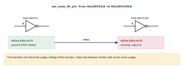
The tool does not check that the two pins work at the same voltage. Thus, copy only between pins of the same supply, and between cells that are electrically similar.
7.4 Boundary conditions at the ports
The tool does not know what drives the block's input ports, or what the outputs drive. The designer supplies this with port constraints. Figure 16 summarizes them.
set_driving_cell– sets the holding resistance of the driver on an input port. A weak holder lets a bigger bump through, so a missing or weak driving cell makes port victims look worse.set_input_transition– sets the input slew. If no transition is given, the tool uses 5 ps. This is a very fast edge, so port attackers look very aggressive.set_load– sets the load on output ports.set_case_analysis– an attacker held at a constant cannot switch, so it is silenced.set_false_path, multicycle paths and clock uncertainty – these have no effect with infinite windows.
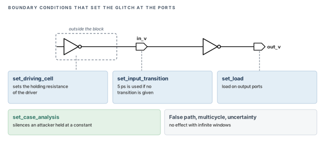
Why do path exceptions not help? With infinite windows, the tool does not use timing to decide when an attacker can switch. A false path only changes timing checks. It does not stop a net from toggling. A constant from case analysis does stop it.
Always give input ports a driving cell and a realistic transition before a glitch run. The 5 ps default makes every port attacker look very aggressive.
8 Worked example: a clock pin glitch
Let us join the pieces on a small block. The assumptions are written at the point of use.
The task. A block runs at VDD = 0.9 V. A clock net clk_g runs beside a data bus that switches every cycle. The block owner wants every clock pin protected, and a reliability check of rail violations.
Step 1 – set up and set the limits
We read the design with noise data, so that the ROP check is possible. We give the input ports a realistic driver and a realistic edge. Without the edge, the tool would use the default 5 ps transition. Then we set a strict ROP limit on clock pins only.
# Assuming noise data in cdB form and a 16 nm node
tempus> read_lib typ.lib -cdb typ.cdB           ;# timing plus noise
tempus> read_verilog blk.v                      ;# netlist
tempus> set_top_module blk                      ;# link
tempus> set_design_mode -process 16             ;# node defaults
tempus> read_sdc blk.sdc                        ;# constraints
tempus> read_spef blk.spef.gz                   ;# parasitics
tempus> set_driving_cell -lib_cell BUFX4 [all_inputs]   ;# realistic holders
tempus> set_input_transition 0.05 [all_inputs]  ;# 50 ps edge, illustrative
tempus> set_delay_cal_mode -siAware true        ;# crosstalk on
tempus> set_si_mode -enable_glitch_report true \
          -enable_glitch_propagation true       ;# keep and propagate glitches
tempus> set_glitch_threshold -failure_point last -pin_type clock \
          -threshold_type failure -value 0.2    ;# clock ROP limit: 0.18 V
Step 2 – run and report
We run the analysis, then ask only for failures. The failure list is the work list.
tempus> check_noise                             ;# check before the run
tempus> update_glitch                           ;# glitch analysis
tempus> report_noise -failure -txtfile clk_fail.txt   ;# failures to fix
Step 3 – read the result
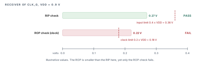
Assume the report shows the receiver of clk_g with an RIP of 0.27 V and an ROP of 0.22 V. These values are illustrative. Figure 17 places them against the two limits.
- No
set_glitch_threshold -failure_point inputwas given, so the default input limit applies: 0.4 × 0.9 = 0.36 V. - The RIP of 0.27 V is below 0.36 V. Thus, the RIP check passes.
- The ROP limit on clock pins is 0.2 × 0.9 = 0.18 V. The ROP of 0.22 V is above it. Thus, the ROP check fails.
- Because the ROP fails, the glitch is not propagated further. It appears once, at this receiver.
The fix is usually physical – more spacing or shielding for clk_g, or a stronger driver. Those fixes belong to Signoff ECO. After the fix, rerun Step 2 and compare the new failure file with the old one.
Step 4 – check the rails
Finally, we turn on the reliability check. We use a limit of 0.3 of VDD for both rail types.
tempus> set_si_mode -enable_overshoot_undershoot_glitch true   ;# VLU and VHO on
tempus> set_glitch_threshold -glitch_type vlu -value 0.3       ;# undershoot: 0.3 of VDD
tempus> set_glitch_threshold -glitch_type vho -value 0.3       ;# overshoot: 0.3 of VDD
tempus> update_glitch                                          ;# rerun
tempus> report_noise -failure -overshoot_undershoot \
          -txtfile rails.rpt                                   ;# rail failures only
The -overshoot_undershoot filter keeps this report apart from the logic glitches. Thus, the reliability list can go to a different reviewer if needed.
set_driving_cell and set_input_transition in Step 1 use common forms of these commands. Confirm the options with help for your libraries and time units.
9 Common mistakes and how to catch them
Table 3 gathers the mistakes from this chapter. Each row starts with the symptom you would see first.
| Symptom | Likely cause | Fix |
|---|---|---|
| No glitch results at all | -siAware true or -enable_glitch_report true not set |
Set both before update_glitch |
| Only RIP results, no ROP | No noise models (cdB, ECSM-N, CCS-N) read | Read libraries with noise data, for example -cdb |
| Clean RIP, failing silicon | ROP larger than RIP was never checked | Run the ROP check with VIVO data |
| A glitch does not appear on the next stage | It failed its ROP, or passed through a multi-stage cell | Expected behavior; fix the first failure |
| A net with little coupling fails | Glitch propagated from an earlier stage | Look one or two stages back |
| Many port glitches look huge | No input transition, so 5 ps is used | Set set_input_transition and set_driving_cell |
| A false path did not remove a glitch | Path exceptions have no effect with infinite windows | Use set_case_analysis if the attacker is truly constant |
Changed -input_glitch_threshold has no effect |
set_glitch_threshold overrides it |
Keep one method per script |
| Too many pessimistic glitches | Infinite windows kept with -use_infinite_TW true |
Use real windows once constraints are clean |
| VLU/VHO failures mixed with logic glitches | Report not filtered | Add -overshoot_undershoot |
| Copied noise data gives odd results | set_noise_lib_pin between pins of different voltage |
Copy only between pins of the same supply |
| A glitch vanished after a script change | A set_quiet_attacker was added (status UF) |
Check every UF entry has a written reason |
10 Interview preparation
A short crosstalk bump on a net that should be quiet, caused by a switching neighbor.
- The coupling capacitance pushes charge onto the quiet net, and its driver pulls it back.
- It can flip a receiver's logic value or create a false clock edge.
- It does not show up as negative slack, so a separate check is needed.
VL: the victim is low and the attacker rises. VH: the victim is high and the attacker falls.
- In both, the bump moves toward the middle of the swing.
- The middle of the swing is where a receiver decides between 0 and 1, so these bumps threaten logic.
RIP is the bump at the receiver input; ROP is the resulting bump at the receiver output.
- The RIP check needs no noise data; the ROP check needs VIVO tables.
- A receiver filters small bumps and can amplify bumps near its switching point.
- Thus, ROP can be larger than RIP, and a passing RIP does not prove safety.
At the output of the first internal stage.
- For combinational cells, that internal node has a default limit of 30% of VDD.
- The glitch does not propagate through a multi-stage cell.
Passing glitches through single-stage cells only.
- A failing ROP is reported and not propagated, so it is not counted twice.
- Multi-stage cells stop propagation.
- Propagation runs inside
update_glitch, or before timing updates with-enable_glitch_propagation true.
With real windows, attackers that cannot switch together are not added, so the glitch shrinks.
- Infinite windows assume any attacker can switch at any time: safe but pessimistic.
- The second
update_glitchiteration uses real windows unless-use_infinite_TW trueis set. - Real windows are only as good as the constraints behind them.
Undershoot below 0 V and overshoot above VDD; they stress gate oxide.
- They occur when the attacker moves in the victim's own direction.
- They are reliability checks: RIP-style limit only, no ROP and no propagation.
report_noise -overshoot_undershootreports only these.
set_glitch_threshold and set_si_mode -input_glitch_threshold. Which one applies?set_glitch_threshold overrides -input_glitch_threshold.
- The default input threshold is 0.4 of VDD.
- Mixing both styles in one script hides which limit is active.
No. With infinite windows, false paths, multicycle paths and clock uncertainty have no effect.
- A false path changes timing checks, but it does not stop a net from toggling.
set_case_analysisdoes silence an attacker held at a constant.
The port's boundary conditions: input transition and driving cell.
- With no transition given, the tool uses 5 ps, a very fast edge.
set_driving_cellsets the holding resistance; a weak holder lets bigger bumps through.set_loadcovers output ports.
set_annotated_glitch?To apply a known glitch, such as noise arriving from the top level, at a pin.
- At a driver it is combined with the computed glitch; at a receiver it overrides RIP.
- The waveform is a PWL list of time and voltage pairs; a VH waveform is written from 0 V.
Chapter recap
Key takeaways
- A glitch is a crosstalk bump on a quiet net. VL rises from 0 V, VH falls from VDD.
- RIP is checked against a VDD ratio (default 0.4) with no noise data. ROP needs VIVO tables and can exceed RIP.
- In multi-stage cells, ROP is measured at the first stage; the internal node default is 30% of VDD.
- Passing glitches propagate through single-stage cells; failing ones stop and are reported.
- The second
update_glitchiteration uses real windows unless-use_infinite_TW trueis set. - VLU and VHO are reliability checks with a RIP-style limit only.
set_glitch_thresholdoverrides-input_glitch_threshold.- Port boundary conditions matter: 5 ps is used when no input transition is given.
Command recap
| Command | Purpose |
|---|---|
read_lib -cdb |
Read noise data with the library |
set_delay_cal_mode -siAware true |
Turn on crosstalk-aware analysis |
set_si_mode -enable_glitch_report, -enable_glitch_propagation |
Keep glitch results; propagate glitches |
check_noise, update_glitch |
Check, then run, the glitch analysis |
set_si_mode -input_glitch_threshold, -input_glitch_vh_threshold, -input_glitch_vl_threshold |
RIP limits |
set_si_mode -receiver_peak_limit, -receiver_clk_peak_limit, -receiver_latch_peak_limit |
ROP limits |
set_glitch_threshold -failure_point, -pin_type, -glitch_type |
General glitch limits |
set_si_mode -use_infinite_TW |
Infinite windows in iteration 2 |
set_si_mode -enable_overshoot_undershoot_glitch |
VLU and VHO checks |
report_noise |
Glitch reports and filters |
set_quiet_attacker |
Quiet attackers (status UF) |
set_annotated_glitch |
Apply a PWL glitch at a pin |
set_noise_lib_pin |
Copy noise data between pins |
set_driving_cell, set_input_transition, set_load |
Port boundary conditions |
set_case_analysis |
Silence an attacker held at a constant |
Compact glossary
| Term | Meaning |
|---|---|
| Glitch | A crosstalk bump on a net that should be quiet |
| Victim / attacker | The quiet net / the switching neighbor that couples onto it |
| Coupling capacitance | The capacitance between two neighboring wires |
| VL / VH | Bump up from 0 V / bump down from VDD |
| VLU / VHO | Undershoot below 0 V / overshoot above VDD |
| RIP | Receiver input peak |
| ROP | Receiver output peak |
| VIVO table | Voltage-in, voltage-out noise data for a receiver |
| Multi-stage cell | A library cell with more than one internal stage |
| Timing window | The time range in which a net can switch |
| Infinite timing window | The assumption that a net can switch at any time |
| PWL | Piecewise linear: a waveform given as time and voltage pairs |
Practical perspective
On a real project, glitch failures usually cluster on a few long, parallel routes – clocks, resets and enables. A good habit is to fix the ROP failures on clock pins first, because they can break the chip outright. Then work through data pins and, finally, the reliability report. Keep every quiet attacker and annotated glitch in a reviewed list, because each one hides a result.
What comes next
So far every delay came from one set of library and parasitic values. Real silicon varies across the chip. The next chapter, Analysis Modes, CPPR and AOCV, shows how the tool models that variation. It also shows how to remove the pessimism it adds.